Cracking a skill-specific interview, like one for Technical Drawing and Design, requires understanding the nuances of the role. In this blog, we present the questions you’re most likely to encounter, along with insights into how to answer them effectively. Let’s ensure you’re ready to make a strong impression.
Questions Asked in Technical Drawing and Design Interview
Q 1. Explain the difference between orthographic and isometric projections.
Orthographic and isometric projections are both ways to represent three-dimensional objects on a two-dimensional plane, but they differ significantly in their approach. Orthographic projection uses multiple views (typically front, top, and side) to show the object from perpendicular directions. Imagine taking photographs of a building from directly in front, above, and to the side – that’s the essence of orthographic projection. Each view shows only two dimensions, but together they reveal the complete shape. Isometric projection, on the other hand, attempts to show a single, three-dimensional view of the object. Think of it as a perspective drawing, but with all axes equally foreshortened (reduced in proportion). While helpful for visualization, isometric projections can sometimes be less precise for detailed measurements.
Example: Imagine a simple cube. An orthographic projection would show three separate square views representing the front, top, and side. An isometric projection would show a single image of a cube, slightly distorted, but with all three faces visible at once.
Q 2. What are the common CAD software packages you are proficient in?
I’m proficient in several leading CAD software packages, including AutoCAD, SolidWorks, and Revit. My experience with AutoCAD spans over a decade, focusing on 2D drafting and detailed design. SolidWorks has been instrumental in my 3D modeling work, particularly in projects requiring complex assemblies and detailed analysis. Revit’s strengths lie in its Building Information Modeling (BIM) capabilities, which I’ve utilized extensively for architectural and structural projects. I’m also familiar with Fusion 360 and have undertaken smaller projects using it. My proficiency in these various platforms allows me to adapt to project requirements seamlessly and choose the most appropriate tool for the job.
Q 3. Describe your experience with dimensioning and tolerancing.
Dimensioning and tolerancing are critical for ensuring that manufactured parts meet design specifications. My experience encompasses applying both geometric dimensioning and tolerancing (GD&T) and traditional dimensioning techniques. I’m well-versed in using various symbols and notations, such as plus/minus tolerances, limits of size, and positional tolerances, to specify the allowable variations in dimensions and geometrical features. For instance, I’ve worked on projects where specifying a precise hole diameter with a tolerance of ±0.01 mm was essential for the proper functioning of a mechanical assembly. Using GD&T ensures that the parts fit together as intended, even accounting for manufacturing variations.
Example: I recently worked on a project where GD&T symbols were used to define the allowable variations in the position of a critical mounting hole. This prevented costly rework due to misalignment. Understanding these standards is crucial for producing functional and reliable designs.
Q 4. How do you ensure accuracy and precision in your technical drawings?
Accuracy and precision are paramount in technical drawing. I employ a multi-pronged approach to ensure these qualities are consistently met. First, I meticulously follow established standards and best practices for drawing creation. This includes employing appropriate scaling, using precise measurement tools within CAD software, and adhering to company drawing standards. Secondly, I perform rigorous checks and reviews of my work. This often involves peer review with colleagues to identify potential errors or inconsistencies. Thirdly, I leverage the capabilities of CAD software to perform various checks like geometrical constraints to guarantee dimensional accuracy and consistency throughout the model.
Example: On a complex assembly drawing, I used the ‘measure’ tool to verify that critical distances were within the specified tolerances. I also conducted a design review with a colleague, obtaining their feedback to identify any issues early on.
Q 5. What are your preferred methods for creating detailed sections and elevations?
Creating detailed sections and elevations is crucial for conveying the internal structure and features of a design. My preferred method involves utilizing the sectioning tools within CAD software. These allow me to create various types of sections, such as full sections, half sections, and broken-out sections, depending on the complexity of the design and the information to be conveyed. I carefully select section planes to best highlight crucial elements and use clear hatching patterns to indicate different materials. For elevations, I utilize the software’s elevation creation commands to generate precise views of the object’s vertical features. Careful labelling and clear annotation further enhance the understanding of these views.
Example: In a building design, I would create several sections to depict the structure’s interior layouts, showing wall thicknesses, beam positions, and plumbing runs. Elevations provided clear visual representations of exterior façade elements.
Q 6. Explain your understanding of different drawing scales and their applications.
Drawing scales are essential for representing objects at manageable sizes on paper or a screen. They are ratios that establish the relationship between the dimensions in the drawing and the actual dimensions of the object. Common scales include 1:1 (full size), 1:10 (one unit on the drawing represents ten units in reality), and 1:100. The choice of scale depends on the object’s size and the level of detail required. Large objects, like buildings, typically use smaller scales for representation, while smaller components might use larger scales or even full-size drawings for detailed work.
Example: A house plan might use a scale of 1:50 to fit the entire layout on a standard-sized sheet, while a detailed drawing of a door handle might be drawn at a scale of 2:1 or even full-size for precision.
Q 7. How do you manage revisions and updates to technical drawings?
Managing revisions and updates to technical drawings is vital to maintain accuracy and control. I typically use a revision control system, either integrated within the CAD software or through a dedicated platform. This usually involves creating a new revision number (e.g., A, B, C) for each change, along with a description of the alterations made. Revision clouds are used to clearly highlight the specific modifications on the drawing. A revision log is maintained to document the changes, the date of the change, and the person who made the change. This ensures a clear audit trail of all modifications, promoting accuracy and accountability.
Example: If a dimension needs to be corrected, I would create a new revision of the drawing, add a revision cloud around the corrected dimension, update the revision table, and record the changes in the revision log.
Q 8. Describe your experience with creating and managing drawing layers.
Managing drawing layers is fundamental to organizing complex designs. Think of layers like transparent sheets stacked on top of each other. Each layer contains specific elements, allowing for independent manipulation and control. For instance, one layer might hold the building’s structure, another the electrical systems, and another the plumbing. This prevents accidental modification and allows for selective visibility.
My experience includes utilizing layer management features in various CAD software like AutoCAD, SolidWorks, and Revit. I consistently employ a naming convention (e.g., using prefixes indicating layer function like “STR-” for structure or “ELE-” for electrical) for easy identification and organization. Furthermore, I utilize layer states to temporarily hide or freeze layers during specific design phases, enhancing clarity and simplifying the drawing interface. For example, when focusing on the structural design, I might freeze layers related to MEP (Mechanical, Electrical, and Plumbing) systems to minimize clutter. This approach improves efficiency and collaboration, particularly in large projects with multiple contributors.
Q 9. How do you handle conflicting design requirements or specifications?
Conflicting design requirements are common, especially in collaborative projects. My approach involves a structured problem-solving method. First, I meticulously document all conflicting requirements, outlining their sources and implications. Then, I analyze the root causes of the conflicts—is it a misunderstanding of specifications, a change in project scope, or a limitation in available resources? A crucial step is prioritizing these conflicting requirements based on project goals and client needs. This may involve discussing trade-offs with the design team and clients. Often, a compromise must be found, and I utilize data-driven analysis (e.g., weight vs. strength calculations) to support the chosen solution. Finally, I document the resolution and update relevant drawings and specifications to reflect the agreed-upon changes.
For example, in a bridge design, a conflict might arise between minimizing material weight and ensuring structural integrity. I would analyze different design options, supported by engineering calculations, presenting them to the team and client to reach a mutually acceptable outcome.
Q 10. Explain your process for creating 3D models from 2D drawings.
Creating 3D models from 2D drawings requires careful interpretation and attention to detail. My process begins with a thorough review of the 2D drawings, verifying dimensions, annotations, and specifications. I then import the 2D drawings into a 3D modeling software (like SolidWorks or Inventor). I use features like sketching and extruding to build up the 3D forms from the 2D geometry. This involves defining the appropriate profiles and using features to create features like holes, cuts, and fillets as indicated on the 2D plan. Often, assumptions need to be made about unseen features, so thorough documentation and communication with the design team are crucial. After building the base model, I perform thorough quality checks, comparing the 3D model to the original 2D drawings to ensure dimensional accuracy and feature completeness.
Imagine transforming a blueprint of a house into a 3D model. I’d start with the walls, then add doors and windows, carefully following the sizes and positions from the drawing. Then, I would use the 2D drawings as guidance to add more complex details like roofing structures and internal partitions.
Q 11. How familiar are you with creating Bills of Materials (BOMs)?
I’m highly proficient in creating Bills of Materials (BOMs). A BOM is a comprehensive list of the raw materials, sub-assemblies, intermediate assemblies, sub-components, parts, and the quantities of each needed to manufacture an end product. My experience includes generating BOMs using various CAD software and spreadsheet programs. I ensure that the BOM includes all necessary information, such as part numbers, descriptions, quantities, and material specifications. I also link the BOM directly to the 3D model, enabling automatic updates when design changes occur. This reduces errors and saves significant time. Furthermore, I can adapt BOM formats to match specific client or manufacturing requirements. For example, I can create BOMs in CSV, Excel, or XML formats depending on the needs.
Q 12. Describe your experience with different types of drafting tools (both digital and manual).
My experience encompasses a wide range of drafting tools. Manually, I’m proficient with pencils, erasers, scales, templates, protractors, and drafting boards. These tools provide a tactile experience and enhance spatial understanding, which is particularly beneficial when working on complex designs. Digitally, I’m proficient with several CAD software packages including AutoCAD, SolidWorks, Inventor, and Revit. Each package offers unique features and benefits; for example, AutoCAD excels in 2D drafting, while SolidWorks is ideal for 3D modeling. I am skilled in using the software’s specialized tools like dimensioning, annotation, and 3D modeling techniques. Moreover, I have experience with 3D scanning and reverse engineering techniques, allowing me to create digital models from physical objects.
Q 13. How do you ensure your drawings comply with relevant industry standards?
Ensuring drawing compliance with industry standards is paramount. This involves understanding and adhering to relevant codes and standards, which vary depending on the industry and project. For example, architectural drawings follow building codes, while mechanical drawings might adhere to ASME (American Society of Mechanical Engineers) standards. My process includes consulting the relevant standard documents throughout the design process. I use the appropriate templates and drawing styles prescribed by the standards. I also meticulously check my drawings for compliance before submission. Furthermore, I’m familiar with various drawing formats and file types (like PDF, DWG, DXF) ensuring compatibility with different software and stakeholders. Regular updates on the latest revisions of standards are crucial, ensuring that my skills and knowledge remain current and relevant.
Q 14. Explain your understanding of geometric dimensioning and tolerancing (GD&T).
Geometric Dimensioning and Tolerancing (GD&T) is a symbolic language used on engineering drawings to define the size, form, orientation, location, and runout of features. It improves clarity and reduces ambiguity compared to traditional tolerancing methods. I understand the various GD&T symbols and their application. For instance, I can accurately specify position tolerances using position symbols, which define the allowable deviation of a feature’s location. Similarly, I can use form tolerances like flatness or straightness to control the deviation from ideal geometric shapes. Understanding GD&T is critical for ensuring the manufacturability and functionality of parts, preventing costly errors and rework. Incorrect application can lead to parts that fail to meet specifications or are unnecessarily difficult to manufacture.
For example, in the design of a precisely fitting mechanical part, GD&T would precisely specify the allowable variations in dimensions and form to ensure that the parts will assemble correctly.
Q 15. How do you handle complex geometric shapes and calculations in your drawings?
Handling complex geometric shapes and calculations in technical drawings relies heavily on a combination of software proficiency and a solid understanding of geometric principles. I utilize CAD software, such as AutoCAD or SolidWorks, which offer powerful tools for creating and manipulating complex 3D models. For instance, parametric modeling allows me to define relationships between different design elements, so changes in one area automatically update related components. This is crucial for managing complex geometries and minimizing errors. Furthermore, I’m adept at using Boolean operations (union, subtraction, intersection) to combine or subtract shapes to create intricate designs. For extremely complex calculations beyond the software’s built-in functions, I might leverage scripting capabilities within the CAD software or utilize specialized mathematical software to ensure precision.
For example, in designing a complex die-casting mold, I’d use parametric modeling to define the shape of the final product and then use Boolean operations to subtract the material that will be removed during the casting process, ensuring all draft angles and parting lines are correctly accounted for. The software automatically updates the design and calculates the volume and surface area, streamlining the process and eliminating manual calculations which are prone to error.
Career Expert Tips:
- Ace those interviews! Prepare effectively by reviewing the Top 50 Most Common Interview Questions on ResumeGemini.
- Navigate your job search with confidence! Explore a wide range of Career Tips on ResumeGemini. Learn about common challenges and recommendations to overcome them.
- Craft the perfect resume! Master the Art of Resume Writing with ResumeGemini’s guide. Showcase your unique qualifications and achievements effectively.
- Don’t miss out on holiday savings! Build your dream resume with ResumeGemini’s ATS optimized templates.
Q 16. Describe your experience working with large-scale projects.
My experience with large-scale projects spans several years and encompasses various industries, including aerospace and automotive. I’ve worked on projects involving teams of over twenty engineers and designers. The key to success in such projects is meticulous planning, a robust version control system, and clear communication. We usually break down large projects into smaller, manageable modules, each with defined deliverables and timelines. This modular approach allows for parallel work streams, speeding up the overall process. A crucial aspect is the use of a centralized data management system, ensuring that everyone works with the most up-to-date drawings and information. For example, on a recent aerospace project involving the design of a large aircraft component, we used a Product Data Management (PDM) system to manage all design files, revisions, and associated documentation. This ensured that everyone on the team had access to the latest revisions and that design changes were properly tracked and documented.
Q 17. How do you collaborate effectively with other team members during the design process?
Effective collaboration is paramount in technical drawing. I consistently utilize various communication and collaboration tools, including regular team meetings, design reviews, and collaborative CAD platforms. Open and honest communication is key; I always ensure that my work is well-documented and easily understandable by others. For example, I frequently use comments and annotations within the CAD software to explain design decisions and rationale. I also believe in active listening and actively seeking feedback from colleagues, which helps identify potential issues early on and promotes a shared understanding of project goals. When disagreements arise, I prioritize finding common ground through constructive discussion and collaborative problem-solving.
Q 18. How do you troubleshoot technical drawing issues and errors?
Troubleshooting technical drawing issues requires a systematic approach. I start by carefully reviewing the drawing for any obvious errors, such as dimensional inconsistencies or missing information. Then I use the software’s built-in tools to check for geometrical errors and conflicts. For example, I might use a feature like ‘interference detection’ in SolidWorks to identify clashes between different components in an assembly. If the issue persists, I systematically trace back the design process, checking each step to isolate the source of the error. Sometimes, the problem might originate from an earlier stage of the design or a misunderstanding of the specifications. I might also consult relevant standards and specifications to ensure compliance and identify potential issues. Finally, documenting the error and the solution is crucial for future reference and to prevent similar issues from occurring again.
Q 19. What is your experience with different file formats used in technical drawing?
My experience with various file formats used in technical drawing is extensive. I am proficient with native CAD formats such as .dwg (AutoCAD), .prt (SolidWorks), .sldasm (SolidWorks assemblies), and .step (STEP), which is a neutral file format for exchanging data between different CAD systems. I’m also familiar with other formats such as .pdf for sharing drawings with clients or other stakeholders, and .dxf for compatibility across various CAD platforms. Understanding the strengths and limitations of each format is crucial to ensure data integrity and compatibility across different software and devices. For example, while .dwg is the native format for AutoCAD and preserves all information, .pdf files are ideal for sharing with clients who might not have CAD software but need to review the drawings.
Q 20. Explain your process for creating detailed assembly drawings.
Creating detailed assembly drawings involves a multi-step process. First, I ensure that all individual component parts are fully modeled and detailed with accurate dimensions and tolerances. Then, I assemble these components in the CAD software, carefully checking for interference and ensuring proper mating relationships. I pay close attention to the creation of exploded views to clearly illustrate the assembly sequence. Next, I add detailed annotations, including part numbers, materials, finishes, and any necessary notes or instructions. Finally, I generate appropriate views and sections to completely describe the assembly. During this process, I frequently refer to established standards such as ASME Y14.5 (Dimensioning and Tolerancing) to ensure consistency and clarity. A bill of materials (BOM) is generated, listing all parts included in the assembly. This comprehensive documentation ensures clarity and facilitates manufacturing and assembly.
Q 21. How do you ensure the clarity and readability of your drawings?
Clarity and readability are paramount in technical drawing. I ensure this by following established drafting standards and best practices. This includes using clear and consistent line weights, appropriate text sizes and fonts, and well-defined views and sections. I use consistent layering within the CAD software to organize the elements of the drawing and avoid visual clutter. Appropriate use of dimensioning and tolerancing is crucial, ensuring that measurements are clearly presented and easily interpreted. Adding clear titles and revision blocks ensures proper identification and tracking of changes. The overall layout should be logically organized to allow easy navigation and comprehension of the information presented. A well-organized and visually appealing drawing is more likely to be understood and used effectively.
Q 22. Describe your experience with creating detailed shop drawings.
Creating detailed shop drawings is crucial for successful construction. It involves translating design concepts into precise, unambiguous instructions for fabrication and installation. My experience encompasses a wide range of projects, from intricate metalwork details to complex HVAC system layouts. I’m proficient in using various software packages like AutoCAD and Revit to produce drawings that meet the highest industry standards. This includes generating orthographic projections (plans, elevations, sections), isometric views, and detailed assembly drawings. For example, on a recent project involving a custom staircase, I produced shop drawings that clearly specified every dimension, material type, and connection detail, ensuring the fabricator could build it precisely to the architect’s design. Another example involved creating detailed shop drawings for prefabricated modular units, ensuring all components were correctly sized and positioned for seamless assembly on-site.
Q 23. How do you utilize annotations and symbols effectively in your drawings?
Annotations and symbols are the language of technical drawing; they provide crucial information concisely and consistently. I use them strategically to convey dimensions, tolerances, material specifications, and assembly instructions. I follow industry standards like ASME Y14.5 for dimensioning and tolerancing, ensuring clarity and preventing misinterpretations. For example, I consistently use leader lines and dimension arrows to show specific measurements, employing clear and consistent fonts for readability. Symbols are used to represent materials (e.g., steel, concrete), finishes, and specific components to avoid lengthy descriptions. I consistently use a key or legend to explain any non-standard symbols used. This allows for easy identification of elements across different drawings. Think of it like a shorthand, allowing for efficient communication without sacrificing precision. Effective annotation and symbolization is key to minimizing errors and streamlining the construction process.
Q 24. How familiar are you with Building Information Modeling (BIM)?
I am highly familiar with Building Information Modeling (BIM). I have extensive experience using Revit, a leading BIM software, to create and manage 3D models of buildings and infrastructure. My proficiency includes developing models, generating detailed drawings from the model, coordinating different disciplines (structural, architectural, MEP), and conducting clash detection analyses. BIM offers significant advantages, including improved collaboration, reduced errors, and enhanced visualization. For instance, on a recent project, using Revit’s clash detection feature, we identified and resolved potential conflicts between MEP systems and structural elements before construction, preventing costly rework on-site. BIM also allows for efficient quantity takeoffs and improved cost estimation, leading to better project management.
Q 25. Describe your experience with different types of design documentation.
My experience covers a wide spectrum of design documentation types including, but not limited to, architectural drawings (plans, sections, elevations, details), structural drawings (foundation plans, framing plans, reinforcing details), MEP drawings (plumbing, electrical, HVAC), and shop drawings (fabrication and installation instructions). I’m also experienced with as-built drawings, which are crucial for record-keeping and future maintenance. Each type requires a specific approach to ensure accuracy and completeness. For example, architectural drawings prioritize aesthetics and spatial organization, while structural drawings focus on load-bearing capacity and construction methods. Understanding the specific needs and conventions for each type is vital for effective communication and successful project delivery.
Q 26. How do you stay up-to-date with the latest advancements in technical drawing software and techniques?
Staying current in the field of technical drawing requires continuous learning. I actively participate in industry workshops and webinars, attend conferences and trade shows, and subscribe to relevant professional journals and online resources. I also engage in online training courses offered by software vendors to enhance my skills and learn about the latest features and functionalities. Furthermore, I regularly review industry best practices and standards (like ISO and ASME) to ensure my work consistently meets the highest quality standards. Continuous professional development ensures that I remain proficient in using the latest tools and techniques, guaranteeing the efficiency and accuracy of my work.
Q 27. Explain your approach to problem-solving in a technical drawing context.
My approach to problem-solving in technical drawing is systematic and iterative. It begins with clearly defining the problem, gathering all relevant information, and understanding the project requirements. Next, I explore potential solutions, often sketching out different approaches before deciding on the optimal one. I prioritize clarity and precision in my drawings, using a layered approach in CAD software to manage complexity. If I encounter a challenge, I might consult relevant standards, seek input from colleagues, or research alternative solutions. Iterative review and refinement are critical; I constantly check for errors, inconsistencies, and potential issues, ensuring the final drawing is accurate, complete, and unambiguous. Think of it like solving a puzzle, requiring careful planning, attention to detail, and a willingness to adapt the approach as needed.
Q 28. Describe a challenging technical drawing project you’ve worked on and how you overcame the difficulties.
One challenging project involved creating shop drawings for a complex curved glass facade. The challenge stemmed from the intricate geometry and the need for extremely precise fabrication tolerances. To overcome this, I utilized parametric modeling techniques in Revit, allowing me to easily adjust the design and automatically update the shop drawings. I also developed a detailed 3D model that could be used for clash detection and coordination with other trades. Regular meetings with the fabricator were essential to address questions and ensure that my drawings accurately reflected their capabilities. This collaborative approach, combined with the precision afforded by parametric modeling, successfully navigated the complexities of this project, resulting in a successful installation.
Key Topics to Learn for Technical Drawing and Design Interview
- Orthographic Projection: Understanding first-angle and third-angle projection methods, and their application in creating detailed technical drawings. Practice translating 3D objects into 2D representations.
- Dimensioning and Tolerancing: Mastering the techniques of accurately dimensioning drawings, including geometric dimensioning and tolerancing (GD&T), to ensure manufacturing precision and consistency. Practice applying various tolerancing symbols and understanding their implications.
- Isometric and Axonometric Projections: Developing proficiency in creating 3D representations using isometric and other axonometric projections, enhancing visualization and communication of design concepts.
- Section Views and Detailing: Understanding the creation and interpretation of section views (full, half, broken, revolved) to reveal internal features and details. Practice creating clear and concise sectional drawings.
- CAD Software Proficiency: Demonstrating practical experience with industry-standard CAD software (AutoCAD, SolidWorks, Revit, etc.) and showcasing your skills in 2D and 3D modeling, drafting, and rendering.
- Material Selection and Properties: Understanding the properties of various materials and their suitability for different applications. Be prepared to discuss factors influencing material choices in design.
- Design Principles and Standards: Familiarity with relevant design standards (e.g., ANSI, ISO) and the principles of good design practice, including clarity, accuracy, and efficiency.
- Problem-Solving and Design Thinking: Be ready to discuss your approach to solving design challenges, emphasizing your ability to analyze problems, develop solutions, and iterate based on feedback.
- Communication and Collaboration: Highlight your skills in effectively communicating technical information through drawings and verbally explaining complex design concepts to both technical and non-technical audiences.
Next Steps
Mastering Technical Drawing and Design is crucial for a successful career in engineering, architecture, and many other related fields. It’s a highly sought-after skill that opens doors to exciting opportunities and career advancement. To increase your job prospects, focus on crafting an ATS-friendly resume that showcases your skills and experience effectively. ResumeGemini is a trusted resource that can help you build a professional and impactful resume. They provide examples of resumes tailored to Technical Drawing and Design to guide you in creating a compelling application.
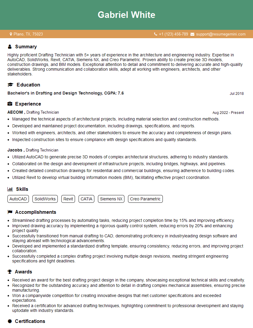
Drafting Technician Resume Sample
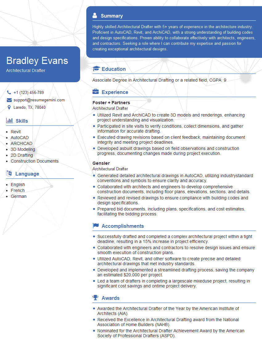
Architectural Drafter Resume Sample
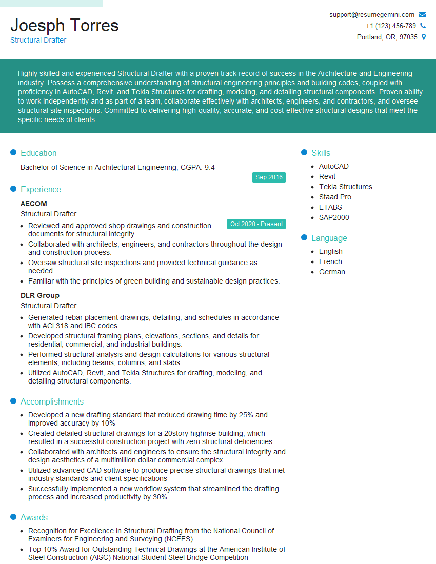
Structural Drafter Resume Sample
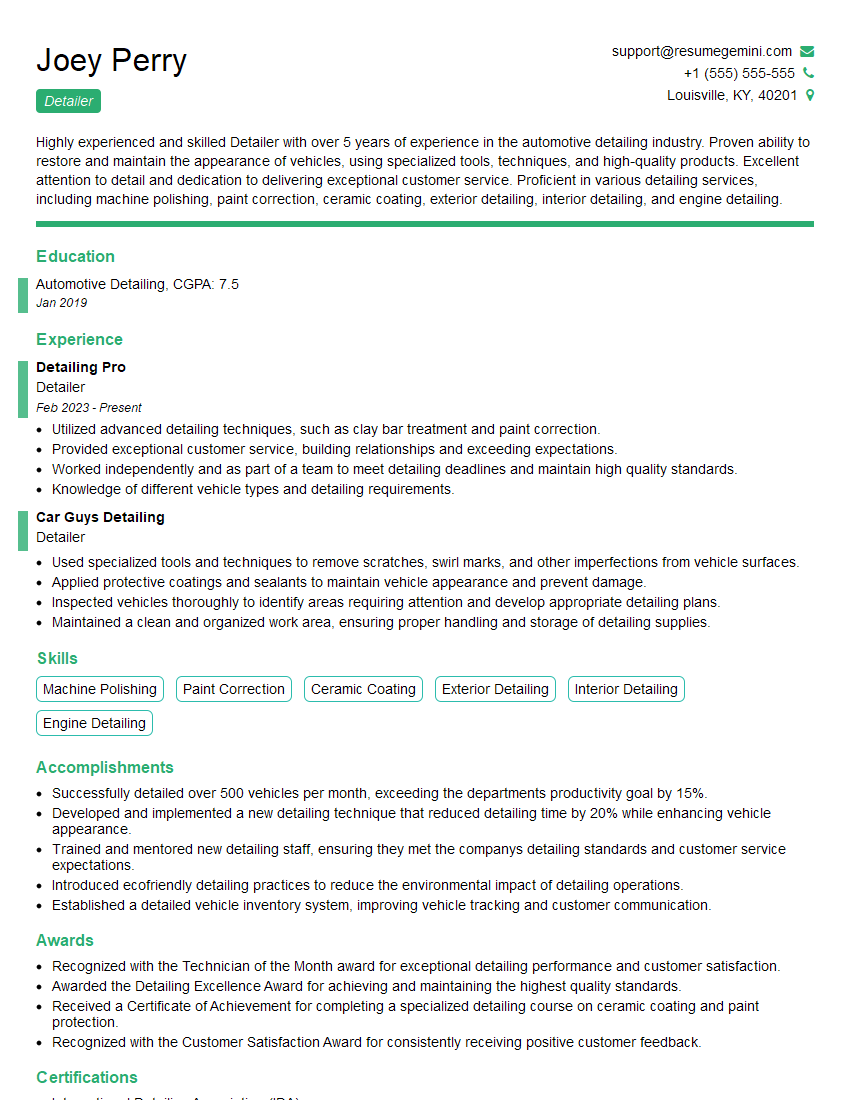
Detailer Resume Sample
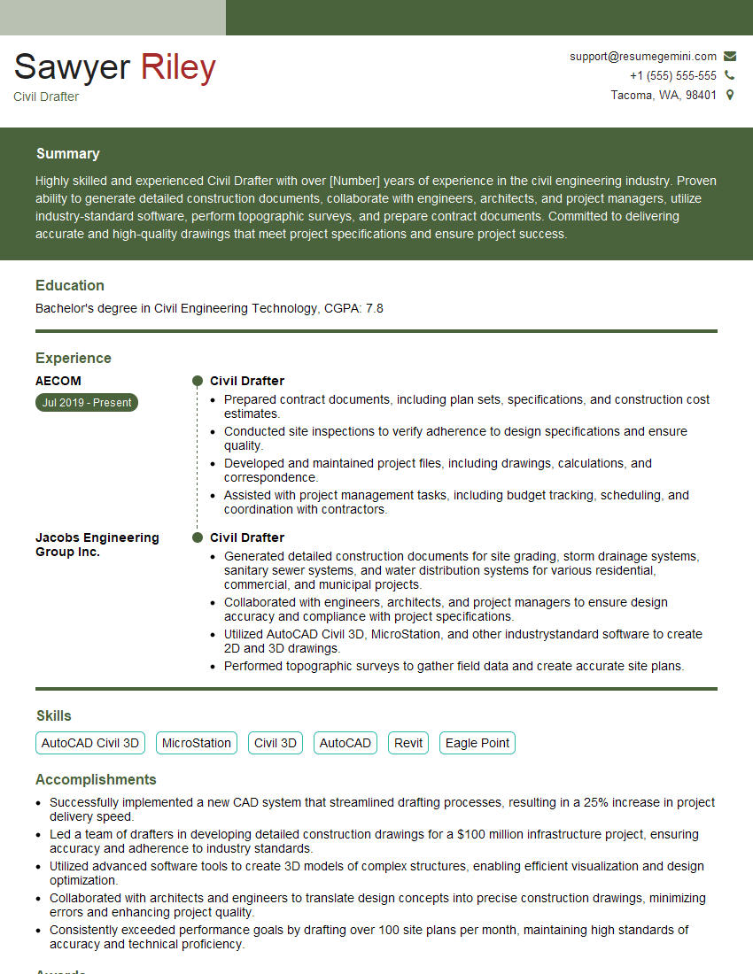
Civil Drafter Resume Sample
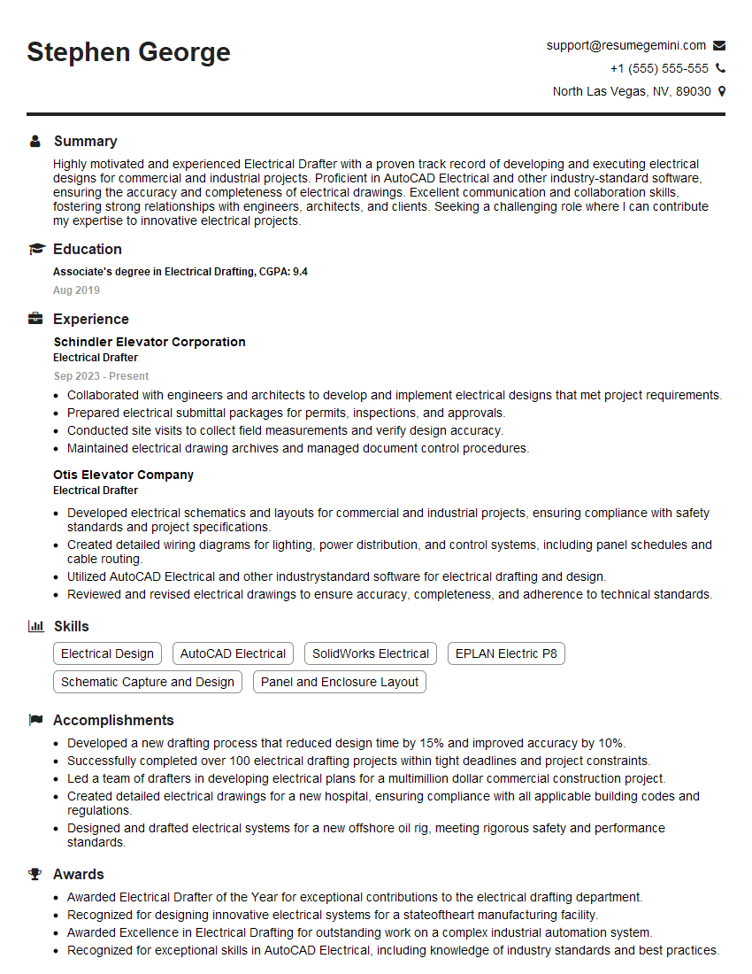
Electrical Drafter Resume Sample
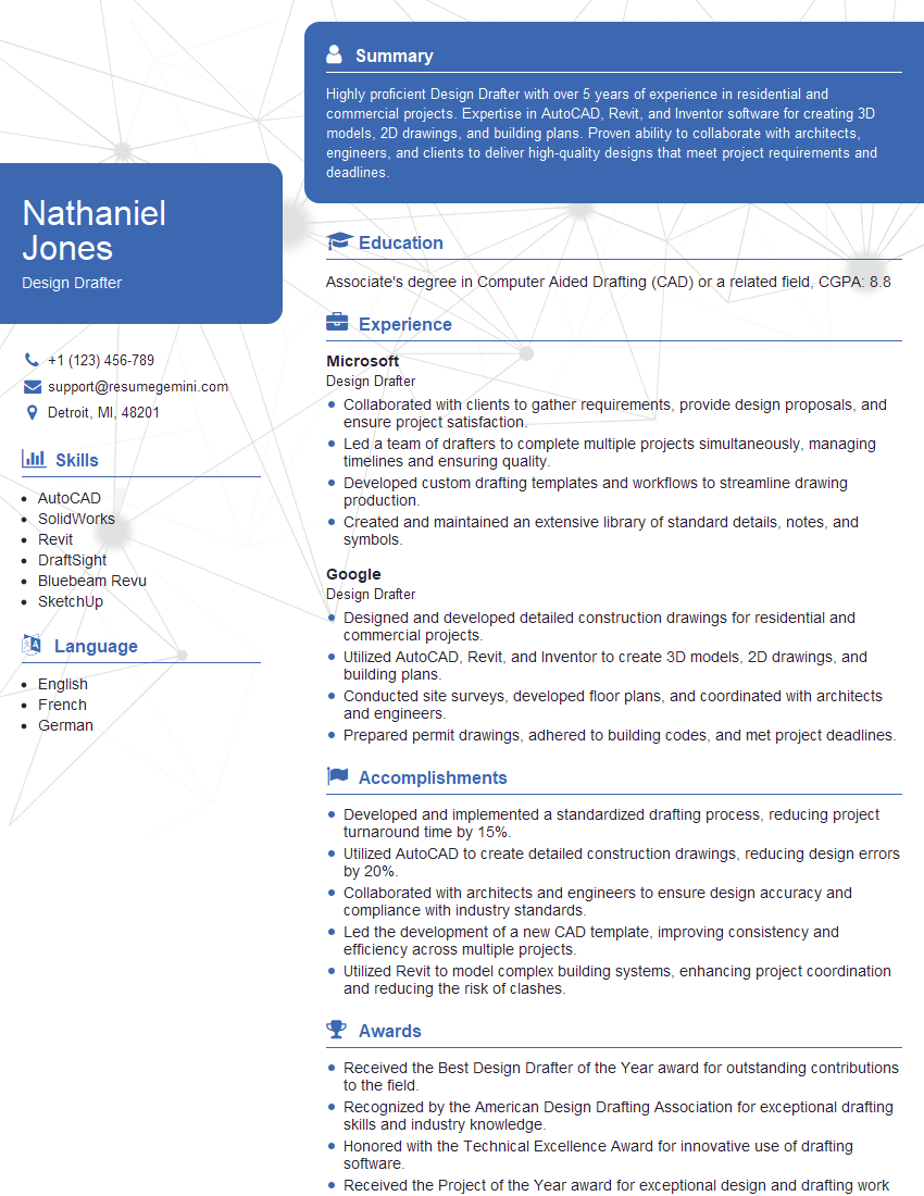
Design Drafter Resume Sample

Design Technician Resume Sample
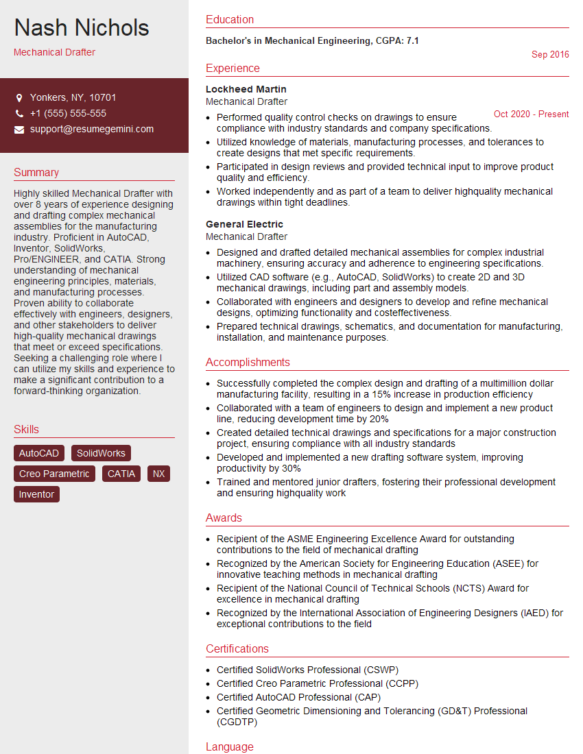
Mechanical Drafter Resume Sample
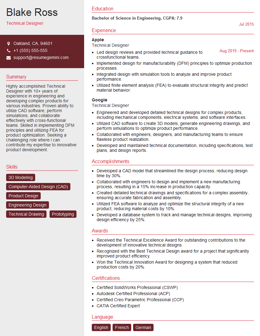
Technical Designer Resume Sample
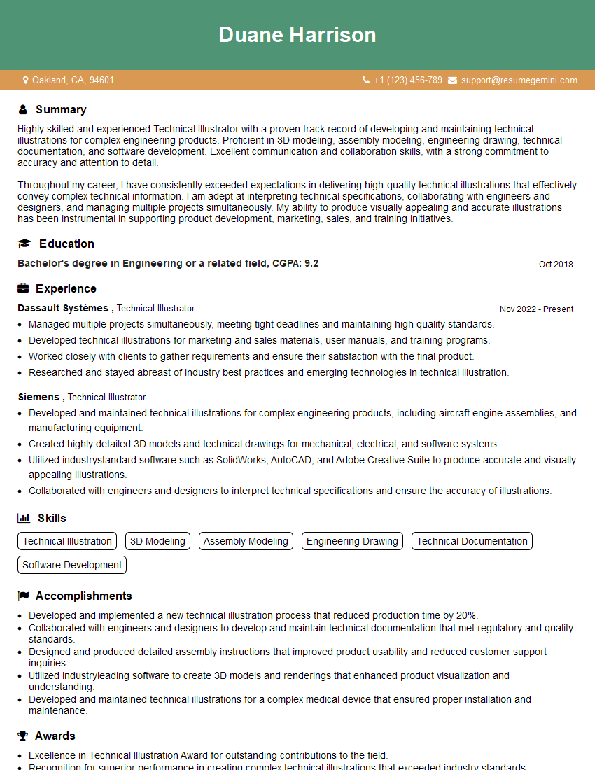
Technical Illustrator Resume Sample
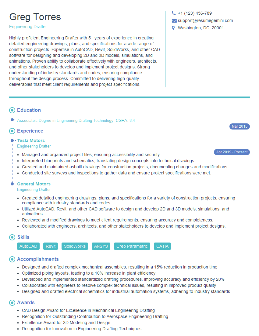
Engineering Drafter Resume Sample
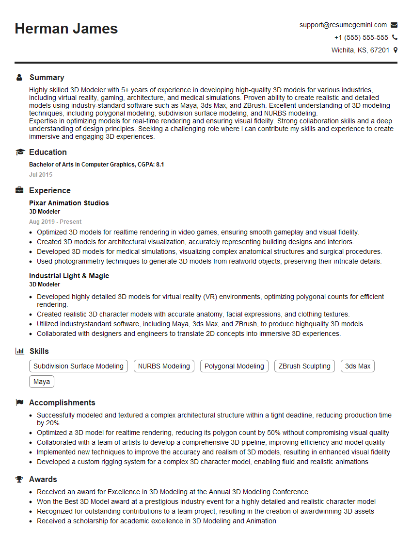
3D Modeler Resume Sample
Explore more articles
Users Rating of Our Blogs
Share Your Experience
We value your feedback! Please rate our content and share your thoughts (optional).
What Readers Say About Our Blog
To the interviewgemini.com Webmaster.
Very helpful and content specific questions to help prepare me for my interview!
Thank you
To the interviewgemini.com Webmaster.
This was kind of a unique content I found around the specialized skills. Very helpful questions and good detailed answers.
Very Helpful blog, thank you Interviewgemini team.