Preparation is the key to success in any interview. In this post, we’ll explore crucial Electrical Engineering Design interview questions and equip you with strategies to craft impactful answers. Whether you’re a beginner or a pro, these tips will elevate your preparation.
Questions Asked in Electrical Engineering Design Interview
Q 1. Explain the difference between AC and DC circuits.
The fundamental difference between AC (Alternating Current) and DC (Direct Current) circuits lies in the direction of electron flow. In DC circuits, electrons flow consistently in one direction, creating a constant voltage. Think of a battery – it provides a steady DC voltage. In AC circuits, the electron flow periodically reverses direction, resulting in a voltage that fluctuates sinusoidally. Our household electricity is a prime example of AC power, constantly changing its polarity.
This difference impacts circuit design significantly. DC circuits are simpler to analyze, often requiring fewer components, while AC circuits introduce concepts like impedance, phase angles, and reactance (resistance to AC current due to capacitance and inductance), making analysis more complex. AC’s ability to easily change voltage using transformers is a major advantage for power transmission over long distances, as it allows for efficient scaling between high-voltage transmission lines and lower-voltage home use.
- DC Applications: Battery-powered devices, integrated circuits, simple resistive circuits.
- AC Applications: Power transmission grids, motors, household appliances.
Q 2. Describe your experience with PCB design software (e.g., Altium, Eagle).
I have extensive experience with Altium Designer, a powerful PCB design software. My proficiency encompasses schematic capture, PCB layout, component placement and routing, signal integrity analysis, and design rule checking (DRC). I’ve used it extensively in projects ranging from low-power embedded systems to high-speed digital circuits. I’m comfortable with advanced features such as differential pair routing, controlled impedance lines, and thermal analysis. In a recent project, I leveraged Altium’s simulation capabilities to verify signal integrity in a high-speed data acquisition system, preventing potential signal degradation and ensuring reliable performance.
While I’m most familiar with Altium, I also have experience with Eagle, primarily for smaller, simpler projects. I’m adept at adapting my skills to different software packages as needed, understanding the core principles of PCB design remain constant regardless of the software used.
Q 3. How do you ensure the electromagnetic compatibility (EMC) of your designs?
Ensuring electromagnetic compatibility (EMC) is critical for reliable and safe electronic devices. My approach is proactive, incorporating EMC considerations throughout the design process, not just as an afterthought. This begins with careful component selection, choosing components with inherently low emissions. Layout design plays a crucial role; techniques like proper grounding, shielding, and controlled impedance routing are essential to minimize interference. I use simulation tools to predict potential EMC issues before the prototype is built, saving time and resources.
After prototyping, I perform rigorous testing to verify the design’s compliance with relevant standards (e.g., FCC, CE). This often involves using specialized test equipment to measure radiated and conducted emissions and immunity to external interference. If issues are found, I systematically troubleshoot using techniques like near-field probing and signal tracing to identify the sources and implement corrective measures. These measures might involve adding filters, improving shielding, or modifying the PCB layout.
Q 4. What are your preferred methods for troubleshooting electrical circuits?
My troubleshooting methodology is systematic and follows a structured approach. I start by carefully observing the symptoms and gathering information. This includes checking power supply voltages, inspecting connections for loose wires or shorts, and reviewing the design documentation. I then use a combination of tools, such as multimeters, oscilloscopes, and logic analyzers, to isolate the faulty component or connection.
If the problem is more complex, I employ a divide-and-conquer strategy, breaking down the circuit into smaller blocks and testing each block individually. In digital circuits, I utilize logic probes and bus analyzers to trace signals and identify timing or logic errors. Software debugging tools are also crucial for diagnosing software-related issues. Documentation is vital throughout the process; I meticulously record my findings, tests performed, and conclusions reached to aid future troubleshooting and analysis. A clear understanding of the circuit’s functionality is key to effective troubleshooting.
Q 5. Explain the concept of impedance matching.
Impedance matching is the practice of designing a circuit to minimize reflections of signals at the interface between two different impedance systems. Imagine trying to push a swing; if you push at the wrong time (mismatched impedance), much of your energy is wasted as the swing bounces back rather than gaining momentum. Similarly, in electrical circuits, if the source impedance doesn’t match the load impedance, signal energy is reflected back towards the source, leading to signal loss and potentially damage to components.
The goal is to maximize power transfer. The ideal impedance match occurs when the source impedance is equal to the complex conjugate of the load impedance. Techniques for achieving impedance matching include using matching networks (e.g., L-networks, pi-networks, using transmission lines), and selecting components with appropriate impedances. In RF and high-frequency circuits, impedance matching is particularly important to ensure efficient signal transmission and minimize signal distortion.
Q 6. Describe your experience with different types of power supplies.
My experience encompasses a wide range of power supply designs, including linear regulators, switching regulators (buck, boost, buck-boost), and isolated power supplies. I understand the trade-offs between efficiency, cost, size, and regulation accuracy for each type. Linear regulators are simple but less efficient, while switching regulators are more complex but offer higher efficiency. Isolated power supplies offer enhanced safety by providing electrical isolation between the input and output. I have worked with both off-the-shelf power supply modules and designed custom power supplies from scratch. In a past project, I designed a highly efficient switching power supply using a buck converter to power a low-power microcontroller system, optimizing for size and minimizing power loss.
My knowledge extends to designing power supplies for various applications, including high-voltage, high-current, and low-noise requirements. Understanding the importance of proper thermal management is crucial in power supply design to prevent overheating and ensure long-term reliability.
Q 7. How familiar are you with different types of transistors and their applications?
I am very familiar with various transistor types and their applications. My knowledge covers bipolar junction transistors (BJTs), field-effect transistors (FETs – including MOSFETs, JFETs), and insulated-gate bipolar transistors (IGBTs). Each type has unique characteristics making them suitable for specific applications.
- BJTs: Excellent for analog applications like amplifiers and current switches due to their current-controlled behavior.
- MOSFETs: Widely used in digital circuits, power electronics, and switching applications due to their high input impedance and voltage-controlled behavior.
- JFETs: Often used in amplifiers requiring high input impedance and low noise.
- IGBTs: Ideal for high-power switching applications such as motor drives and inverters, combining the best features of BJTs and MOSFETs.
My experience extends to selecting appropriate transistors based on factors like voltage and current ratings, gain, switching speed, and noise characteristics. I also understand the importance of proper biasing and thermal management in transistor circuits to ensure optimal performance and reliability. In a past project, I designed a high-efficiency motor driver using IGBTs for a robotic arm application, optimizing for switching speed and power handling capacity.
Q 8. Explain the different types of filters and their applications.
Filters are essential components in electronic circuits, used to selectively pass or attenuate signals based on their frequency. They’re like sieves for signals, allowing certain frequencies to pass through while blocking others. There are several types, categorized primarily by their frequency response:
- Low-pass filters: These allow low-frequency signals to pass through while attenuating high-frequency signals. Think of a bass filter in a music system – it keeps the low, deep sounds while reducing the high-pitched ones. A simple RC circuit is a classic example.
//RC Low-pass filter: Vout = Vin / (1 + jωRC) - High-pass filters: These do the opposite, letting high-frequency signals pass while attenuating low-frequency signals. Imagine a treble filter – it enhances the high notes. Again, a simple RC circuit, but with the output taken across the resistor instead of the capacitor, creates a high-pass filter.
- Band-pass filters: These pass only a specific range of frequencies, blocking both lower and higher frequencies. Think of a radio receiver tuning to a specific station – it selects a narrow band of frequencies around the station’s broadcast frequency while rejecting others.
- Band-stop filters (Notch filters): These attenuate a specific range of frequencies while allowing others to pass. An example would be removing 60Hz hum from a power supply’s output.
- All-pass filters: These filters don’t attenuate any frequencies, but they modify the phase of the signals. They are used in phase correction and delay applications.
Applications span various fields: audio processing, image processing, communication systems (filtering out noise and interference), power supply design (smoothing DC voltage), and control systems (removing unwanted oscillations).
Q 9. What are your experience with signal integrity analysis?
Signal integrity analysis is crucial for high-speed digital designs. It involves analyzing the quality of signals as they travel through the system, ensuring they arrive at their destination without distortion or loss of data. My experience includes using simulation tools like Signal Integrity (SI) simulators (e.g., Keysight ADS, Mentor Graphics HyperLynx) to predict and mitigate signal integrity issues such as reflections, crosstalk, ringing, and EMI/EMC problems. I’ve worked on projects involving high-speed buses like PCIe and DDR, where managing signal integrity was paramount. For example, in a recent project designing a high-speed data acquisition system, I utilized HyperLynx to optimize trace lengths, control impedance, and incorporate appropriate termination techniques to minimize signal reflections and ensure data integrity. This involved collaborating closely with PCB layout engineers to implement the design recommendations effectively. I also have experience with using oscilloscopes and other test equipment to verify signal integrity in the lab.
Q 10. Describe your understanding of thermal management in electronic systems.
Thermal management is critical in electronic systems to ensure reliable operation and prevent component failures due to overheating. My understanding involves several key areas: heat generation mechanisms in electronic components (power dissipation in ICs, resistors, etc.), heat transfer mechanisms (conduction, convection, radiation), and thermal management techniques (heat sinks, fans, liquid cooling). I consider the entire thermal path – from the heat source to the ambient environment – when designing a system. In one project, we faced challenges with a high-power FPGA exceeding its maximum junction temperature. We addressed this by implementing a multi-pronged approach: conducting thermal analysis using simulation software (e.g., ANSYS), selecting a suitable heat sink with adequate surface area and thermal conductivity, and incorporating forced-air cooling. These measures ensured the FPGA operated well within its safe thermal limits. Understanding the principles of thermal resistance and using thermal simulation tools is essential for effective thermal management.
Q 11. How do you ensure the safety and reliability of your designs?
Ensuring safety and reliability are paramount in my design process. This starts with a rigorous adherence to relevant standards and regulations (e.g., UL, IEC, CE). I employ robust design practices, including: component derating (operating components well below their maximum ratings), redundancy (incorporating backup systems where critical), fault tolerance (designing systems to gracefully handle failures), and thorough testing (unit, integration, and system-level testing).
For safety, I focus on aspects like overvoltage and overcurrent protection, grounding and shielding to prevent electrical hazards, and appropriate insulation to avoid shocks. During design reviews, safety is a key discussion point, ensuring all potential hazards are identified and mitigated. I’ve used failure mode and effects analysis (FMEA) to proactively identify and reduce the risk of failures. Documentation and traceability are also critical to ensure long-term reliability and maintainability of the design.
Q 12. Explain your experience with microcontroller programming.
I have extensive experience with microcontroller programming, primarily using C and assembly language. My experience ranges from simple embedded systems to more complex applications. I’m proficient in working with various microcontroller architectures (e.g., ARM Cortex-M, AVR, PIC) and their peripherals (timers, ADC, UART, SPI, I2C). I’ve used real-time operating systems (RTOS) like FreeRTOS for managing tasks and resources in resource-constrained environments. A recent project involved designing a motor control system using a STM32 microcontroller. This required programming the microcontroller to handle real-time feedback from sensors, implement PID control algorithms for precise motor speed regulation, and manage communication with a host computer via a serial interface. I’m also familiar with debugging techniques using tools like JTAG debuggers and logic analyzers.
Q 13. What is your experience with schematic capture and PCB layout?
I’m proficient in schematic capture and PCB layout using industry-standard tools such as Altium Designer, Eagle, and KiCad. Schematic capture involves creating a visual representation of the circuit, defining component properties and connectivity. PCB layout involves arranging the components on a printed circuit board, routing traces, managing signal integrity, and ensuring manufacturability. I understand the importance of DFM (Design for Manufacturing) and DFT (Design for Testing) principles in the layout process. A successful PCB design requires careful consideration of thermal management, signal integrity, and EMC compatibility. I have experience in designing PCBs for various applications, including high-speed digital circuits, analog circuits, and power electronics. For example, on a recent project involving a high-frequency RF circuit, I paid close attention to the trace widths, controlled impedance, and placement of components to minimize signal loss and interference.
Q 14. Explain your understanding of digital signal processing (DSP).
Digital Signal Processing (DSP) is the use of digital processing to perform a wide variety of signal processing operations. My understanding encompasses fundamental concepts like sampling, quantization, discrete-time signals and systems, discrete Fourier transforms (DFT), fast Fourier transforms (FFT), digital filtering, and various algorithms for signal processing tasks. I’m familiar with different DSP architectures and the trade-offs involved in selecting the appropriate hardware and software for a specific application. I have experience using tools like MATLAB and Simulink for DSP algorithm development and simulation. In a project involving audio signal processing, I developed and implemented a digital filter using an FFT to eliminate unwanted noise and distortion from audio signals. This involved selecting the appropriate filter type and order, implementing the algorithm in C for an embedded DSP processor, and verifying its performance through testing. I also have experience in working with various DSP algorithms like FIR, IIR, adaptive filtering and spectral analysis.
Q 15. How do you manage design changes and revisions?
Managing design changes and revisions is crucial in electrical engineering, as projects rarely progress linearly. My approach involves a robust system built around version control, clear communication, and a structured review process.
- Version Control: I utilize tools like Git to track all design modifications, allowing for easy rollback to previous versions if needed. This ensures traceability and minimizes the risk of errors. Each revision is clearly documented with a description of the changes made and the rationale behind them.
- Change Request Management: All design changes are formally documented as change requests. These requests include a detailed description of the proposed modification, its impact on other components, and a risk assessment. This helps maintain project integrity and prevents unforeseen consequences.
- Formal Review Process: Before any change is implemented, a thorough review is conducted by myself and other relevant stakeholders. This involves checking for compatibility, potential conflicts, and adherence to specifications. This step minimizes errors and ensures the overall design remains consistent and functional.
- Communication: Open and clear communication with the team, clients, and other stakeholders is paramount. Regular updates are provided on the progress of changes and any potential delays or issues. This proactive communication ensures everyone remains informed and collaborative.
For example, in a recent project involving the design of a power supply, a change request was submitted to increase the output current. Following my process, we carefully reviewed the impact on thermal management and component selection, updated the schematics and PCB layout accordingly, and thoroughly tested the modified design before implementation.
Career Expert Tips:
- Ace those interviews! Prepare effectively by reviewing the Top 50 Most Common Interview Questions on ResumeGemini.
- Navigate your job search with confidence! Explore a wide range of Career Tips on ResumeGemini. Learn about common challenges and recommendations to overcome them.
- Craft the perfect resume! Master the Art of Resume Writing with ResumeGemini’s guide. Showcase your unique qualifications and achievements effectively.
- Don’t miss out on holiday savings! Build your dream resume with ResumeGemini’s ATS optimized templates.
Q 16. Explain your experience with simulation software (e.g., LTSpice, Multisim).
I have extensive experience with simulation software, primarily LTSpice and Multisim. These tools are indispensable for verifying design functionality and performance before physical prototyping.
- LTSpice: I’m proficient in using LTSpice for simulating analog circuits, including operational amplifiers, power supplies, and filters. I utilize its powerful features for transient and AC analysis to predict circuit behavior under different conditions. For instance, I’ve used LTSpice to optimize the design of a switched-mode power supply, ensuring efficient energy conversion and stable output voltage.
- Multisim: Multisim is my go-to tool for simulating digital circuits and mixed-signal designs. I use it for verifying the functionality of logic gates, microcontrollers, and data acquisition systems. I’ve used Multisim extensively to model and analyze digital control systems for various applications.
I’m comfortable with creating and interpreting simulation results, using them to identify potential design flaws, optimize performance, and refine component selection. The ability to accurately predict circuit behavior through simulation saves time and resources, reducing the need for extensive physical prototyping and debugging.
Q 17. Describe your experience with different testing methodologies.
My experience encompasses a range of testing methodologies, from unit testing to system-level integration testing.
- Unit Testing: I verify the functionality of individual components or modules using dedicated test fixtures. This isolates potential issues and simplifies debugging.
- Integration Testing: I combine individual modules to test their interaction and compatibility. This ensures seamless integration and identifies issues related to communication protocols or timing constraints.
- System-Level Testing: I evaluate the performance of the complete system under realistic operating conditions. This includes functional testing, stress testing, and environmental testing (temperature, humidity, vibration).
- Automated Testing: Whenever feasible, I automate test procedures using scripting languages (e.g., Python) to increase efficiency and reproducibility.
For example, during a recent project involving a motor control system, I developed a comprehensive test plan that included unit tests for the microcontroller firmware, integration tests for communication between the microcontroller and the motor driver, and system-level tests to verify the overall performance and stability of the system under various load conditions.
Q 18. How do you handle conflicting design requirements?
Conflicting design requirements are inevitable in complex projects. My approach involves a structured process of negotiation, prioritization, and trade-off analysis.
- Identify and Document Conflicts: The first step is to clearly identify and document all conflicting requirements. This involves careful review of specifications and stakeholder discussions.
- Prioritization and Negotiation: I work closely with stakeholders to understand the relative importance of each requirement. This often involves weighing factors such as cost, performance, safety, and schedule constraints.
- Trade-off Analysis: When compromises are necessary, I conduct a thorough trade-off analysis to evaluate the impact of different options. This involves quantifying the impact of each decision on various aspects of the design.
- Documentation and Communication: All decisions and compromises are clearly documented and communicated to the relevant stakeholders. This ensures transparency and accountability.
For instance, in a project designing a high-speed data acquisition system, we faced conflicting requirements for high bandwidth and low power consumption. Through careful analysis and negotiation, we opted for a slightly lower bandwidth to achieve significant power savings, a decision supported by a quantitative analysis of its impact on the overall system performance.
Q 19. Explain your experience with design for manufacturing (DFM).
Design for Manufacturing (DFM) is an essential consideration throughout the design process. It involves optimizing the design for efficient and cost-effective manufacturing.
- Component Selection: I select components that are readily available, cost-effective, and suitable for high-volume manufacturing. I avoid using obsolete or hard-to-source components.
- PCB Design: I design PCBs that are manufacturable using standard processes and materials. This involves adhering to industry standards for trace widths, spacing, and via sizes.
- Assembly Considerations: I design the PCB and components to be easily assembled using automated processes. This reduces assembly time and cost.
- Testability: I incorporate design features that enable easy testing during manufacturing. This includes provisions for test points and boundary-scan testing.
In a recent project, implementing DFM principles resulted in a 20% reduction in manufacturing costs by selecting more readily available components and simplifying the PCB layout for automated assembly. This demonstrates the direct impact of DFM on overall project success.
Q 20. How do you prioritize tasks and manage deadlines?
Prioritizing tasks and managing deadlines effectively is crucial for successful project completion. My approach involves a combination of project management techniques and personal discipline.
- Task Breakdown: I break down large projects into smaller, manageable tasks. This provides a clear overview of the work involved and makes it easier to estimate timelines.
- Prioritization: I prioritize tasks based on their importance, urgency, and dependencies. Techniques like the MoSCoW method (Must have, Should have, Could have, Won’t have) are invaluable in this process.
- Scheduling and Tracking: I utilize project management tools (e.g., Microsoft Project, Jira) to schedule tasks, track progress, and identify potential delays.
- Regular Monitoring and Adjustments: I regularly monitor progress and make adjustments to the schedule as needed. This requires flexibility and the ability to adapt to unforeseen circumstances.
For instance, in a fast-paced project with a tight deadline, I used a Kanban board to visually track progress, identify bottlenecks, and re-allocate resources effectively. This allowed us to meet the deadline despite unexpected challenges.
Q 21. Describe a time you had to overcome a significant technical challenge.
One significant technical challenge involved designing a high-precision temperature control system for a scientific instrument. The initial design struggled with significant drift and instability due to unexpected thermal coupling between components.
Initially, our simulations indicated excellent performance. However, during testing, we encountered unexpected temperature variations of up to 5°C, rendering the system unusable. After careful analysis and debugging, we discovered that the heat generated by the microcontroller was affecting the temperature sensor reading, introducing significant drift.
To overcome this, we implemented several solutions:
- Thermal Isolation: We redesigned the PCB to improve thermal isolation between the microcontroller and the sensor using thermally conductive materials.
- Software Compensation: We developed a software algorithm to compensate for the measured drift based on the microcontroller’s internal temperature reading.
- Advanced Calibration Techniques: We incorporated a more sophisticated calibration procedure to accurately compensate for the various thermal effects.
Through these efforts, we reduced the temperature drift to less than 0.1°C, meeting the stringent accuracy requirements. This experience reinforced the importance of thorough analysis, robust testing, and iterative design refinement in tackling complex engineering challenges.
Q 22. Explain your familiarity with various communication protocols (e.g., I2C, SPI, UART).
Communication protocols are the languages that different electronic components use to talk to each other. I have extensive experience with I2C, SPI, and UART, each with its own strengths and weaknesses. Think of it like choosing the right tool for a job – each protocol is best suited for certain tasks.
- I2C (Inter-Integrated Circuit): This is a two-wire serial bus, simple to implement and uses less wiring. It’s ideal for low-speed, low-data-rate communication between microcontrollers and peripherals like sensors and memory chips. I’ve used it extensively in projects involving environmental monitoring systems, where several sensors need to communicate with a central microcontroller. A key feature is its inherent ability to address multiple devices on the same bus.
- SPI (Serial Peripheral Interface): SPI is another serial bus, but it typically uses four wires (MOSI, MISO, SCK, and SS/CS). It offers higher speed and data throughput compared to I2C, making it suitable for applications requiring faster communication, such as interfacing with high-speed ADCs or displays. For example, I utilized SPI in a high-speed data acquisition system for a research project where sampling rate was critical.
- UART (Universal Asynchronous Receiver/Transmitter): UART uses a single wire to send and receive data asynchronously, meaning there’s no need for a synchronized clock signal. It’s commonly used for communication over longer distances and is simpler to debug compared to SPI or I2C, though it’s generally slower. A classic example is using UART for debugging or communicating with a PC via a serial port.
Choosing the right protocol depends on factors such as data rate requirements, number of devices, distance, and complexity of implementation. My design decisions always prioritize the most efficient and robust solution for the given application.
Q 23. How do you ensure your designs meet regulatory standards (e.g., UL, CE)?
Ensuring designs meet regulatory standards like UL (Underwriters Laboratories) and CE (Conformité Européenne) is paramount. It’s not just about ticking boxes; it’s about ensuring safety and reliability. My approach involves a multi-stage process:
- Early Stage Compliance Planning: From the initial design phase, I incorporate regulatory requirements. This includes choosing components with appropriate certifications and designing circuits that inherently meet safety standards. For example, selecting UL-certified power supplies and designing robust grounding schemes are crucial.
- Design for Manufacturing (DFM): Designing for manufacturability considers potential hazards during production. This means minimizing sharp edges, ensuring proper component spacing, and using materials that meet regulatory flammability requirements.
- Testing and Verification: Rigorous testing is essential. This involves conducting EMC (Electromagnetic Compatibility) testing to ensure the design doesn’t emit or is susceptible to harmful electromagnetic interference. Safety tests, including dielectric strength testing and insulation resistance checks, are crucial for UL and CE compliance. We also create and adhere to strict documentation procedures.
- Documentation: Comprehensive documentation is vital for demonstrating compliance. This includes schematic diagrams, PCB layouts, bills of materials (BOM), and test reports. Detailed risk assessments are also an important part of this process.
Furthermore, I stay updated on the latest regulatory changes and collaborate with regulatory compliance experts as needed. Meeting these standards is non-negotiable; it’s essential for product safety and market access.
Q 24. Describe your experience with power electronics.
Power electronics is a core area of my expertise. I’m experienced in designing and analyzing circuits that control and convert electrical power. This involves working with various components like rectifiers, inverters, DC-DC converters, and motor drivers.
For instance, I designed a high-efficiency DC-DC converter for a battery-powered device, optimizing for size, efficiency, and thermal management. This involved selecting appropriate switching transistors, designing the control circuitry using a microcontroller, and implementing protection mechanisms like over-current and over-voltage protection. In another project, I designed a motor control system for a robotic arm, utilizing a three-phase inverter to control the speed and torque of the motors. This included considerations for PWM (Pulse Width Modulation) techniques, sensorless control strategies, and thermal management to prevent overheating.
My understanding extends to various power electronic topologies, switching techniques, and control algorithms. I consider factors such as efficiency, power density, reliability, and cost optimization during the design process. Simulation tools like PSIM and MATLAB/Simulink are essential for modelling and analyzing these complex systems before building physical prototypes.
Q 25. Explain your understanding of different types of sensors and their applications.
Sensors are the eyes and ears of many electronic systems, providing crucial information about the environment. I have experience working with a broad range of sensors, including:
- Temperature sensors (thermistors, thermocouples, RTDs): Used in countless applications from climate control to industrial process monitoring. I’ve used them extensively in projects involving thermal management and environmental monitoring.
- Pressure sensors: Crucial for applications like automotive systems, industrial automation, and medical devices. I’ve incorporated them into designs for pressure control systems and flow measurement systems.
- Optical sensors (photodiodes, phototransistors): Used in everything from light measurement to object detection. I’ve integrated these into systems for optical sensing and proximity detection.
- Accelerometers and gyroscopes: Essential for motion sensing and inertial navigation systems. I’ve utilized them in robotics projects and motion-tracking applications.
- Ultrasonic sensors: Used for distance measurement and obstacle avoidance, often found in robotics and automation systems. I’ve worked with these extensively in various autonomous navigation systems.
Selecting the right sensor is crucial and depends on the application’s specific requirements, such as accuracy, range, resolution, and environmental conditions. My experience enables me to choose and integrate sensors effectively, ensuring accurate data acquisition and reliable system operation.
Q 26. What is your experience with analog-to-digital and digital-to-analog converters?
Analog-to-digital converters (ADCs) and digital-to-analog converters (DACs) are essential building blocks in mixed-signal systems. They bridge the gap between the analog world (continuous signals) and the digital world (discrete signals).
My experience includes working with various types of ADCs and DACs, including successive approximation ADCs, sigma-delta ADCs, and R-2R ladder DACs. I understand the key performance parameters of these converters, such as resolution, sampling rate, accuracy, and linearity. I have used ADCs to digitize sensor readings in several projects, ensuring accurate and reliable data acquisition. For example, I designed a data acquisition system for biomedical signal processing, carefully selecting the ADC to ensure high resolution and low noise in the captured signals.
DACs are used to convert digital control signals into analog outputs to drive actuators or control analog processes. I have integrated DACs in projects involving motor control and generating analog waveforms. Understanding the limitations and characteristics of both ADCs and DACs is crucial for effective system design. I always consider factors such as signal noise, quantization error, and sampling rate when selecting and implementing these components.
Q 27. Describe your experience with embedded software development.
I have substantial experience in embedded software development, primarily using C and C++. My experience spans across various microcontroller architectures, including ARM Cortex-M and AVR microcontrollers. My skills include:
- Real-time operating systems (RTOS): I’m proficient in using RTOS such as FreeRTOS for managing concurrent tasks and real-time constraints. This is crucial for applications where timing is critical, like motor control or data acquisition systems.
- Peripheral control: I’m skilled in programming various peripherals, such as timers, UARTs, SPI, I2C, ADCs, DACs, and DMA controllers. I can efficiently configure and control these peripherals to achieve specific functionality.
- Low-level programming: I’m comfortable with bit manipulation and low-level register access, which is often necessary for optimizing performance and managing resources in embedded systems.
- Debugging and testing: I utilize various debugging tools and techniques, including JTAG debuggers and logic analyzers, to identify and resolve software issues. I also employ rigorous testing methods to ensure software reliability.
I’ve worked on projects ranging from simple control systems to complex data acquisition and processing systems. I always prioritize writing efficient, maintainable, and well-documented code. A recent project involved developing firmware for a wireless sensor network, utilizing low-power techniques to extend battery life while maintaining real-time data transmission.
Q 28. Explain your understanding of different types of memory (e.g., RAM, ROM, Flash).
Memory types play a crucial role in embedded system design. Each type has unique characteristics regarding speed, cost, and volatility (whether data is lost when power is removed).
- RAM (Random Access Memory): RAM is volatile memory; its contents are lost when power is turned off. It’s used for storing data that needs to be accessed quickly, such as program variables and active data. There are different types of RAM, like SRAM (Static RAM) and DRAM (Dynamic RAM), each having trade-offs in speed, cost, and power consumption.
- ROM (Read-Only Memory): ROM is non-volatile memory; data is retained even when power is off. It’s commonly used to store the program code itself (firmware) or other permanent data. Different types of ROM exist, such as PROM (Programmable ROM), EPROM (Erasable PROM), and EEPROM (Electrically Erasable PROM).
- Flash Memory: Flash memory is non-volatile and allows for data to be written and erased in blocks. It’s often used for storing program code, configuration data, and data logging. It’s slower than RAM but offers higher storage capacity and non-volatility.
Choosing the right type and amount of memory is crucial for system performance and cost. For example, in a resource-constrained embedded system, I might carefully balance the use of fast SRAM for critical data and slower Flash memory for program code and non-volatile data storage. Understanding the memory map and memory management is critical for efficient embedded system design.
Key Topics to Learn for Electrical Engineering Design Interview
- Circuit Analysis & Design: Understanding fundamental circuit laws (Ohm’s Law, Kirchhoff’s Laws), AC/DC circuit analysis techniques, and the design of various circuits like filters, amplifiers, and oscillators. Consider exploring different circuit simulation software and their applications.
- Digital Logic Design: Mastering Boolean algebra, logic gates, combinational and sequential circuits, state machines, and practical applications in digital systems design. Focus on practical problem-solving involving logic circuit optimization and troubleshooting.
- Embedded Systems: Familiarity with microcontrollers, microprocessors, real-time operating systems (RTOS), and the design of embedded systems. Explore case studies showcasing successful embedded system implementations.
- Power Systems: Understanding power generation, transmission, distribution, and protection. Explore different power system topologies and their advantages and disadvantages. Practice analyzing power system stability and fault conditions.
- Signal Processing: Grasping concepts of signal analysis, filtering, and digital signal processing (DSP). Consider practical applications in areas like communication systems and instrumentation.
- Electromagnetics: A strong understanding of electromagnetic fields, wave propagation, and antennas. Focus on problem-solving involving antenna design and electromagnetic interference (EMI) mitigation.
- Control Systems: Understanding feedback control systems, system modeling, stability analysis, and controller design techniques. Explore different control strategies and their applications in various systems.
Next Steps
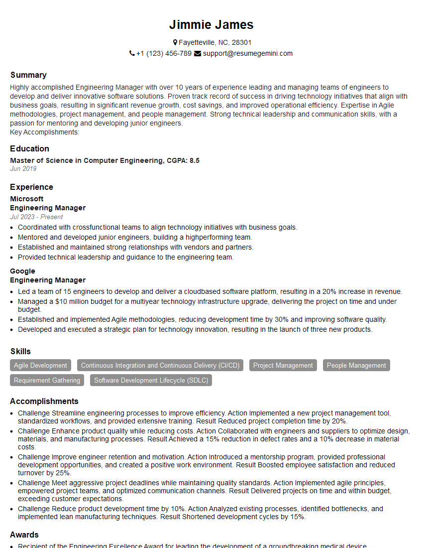
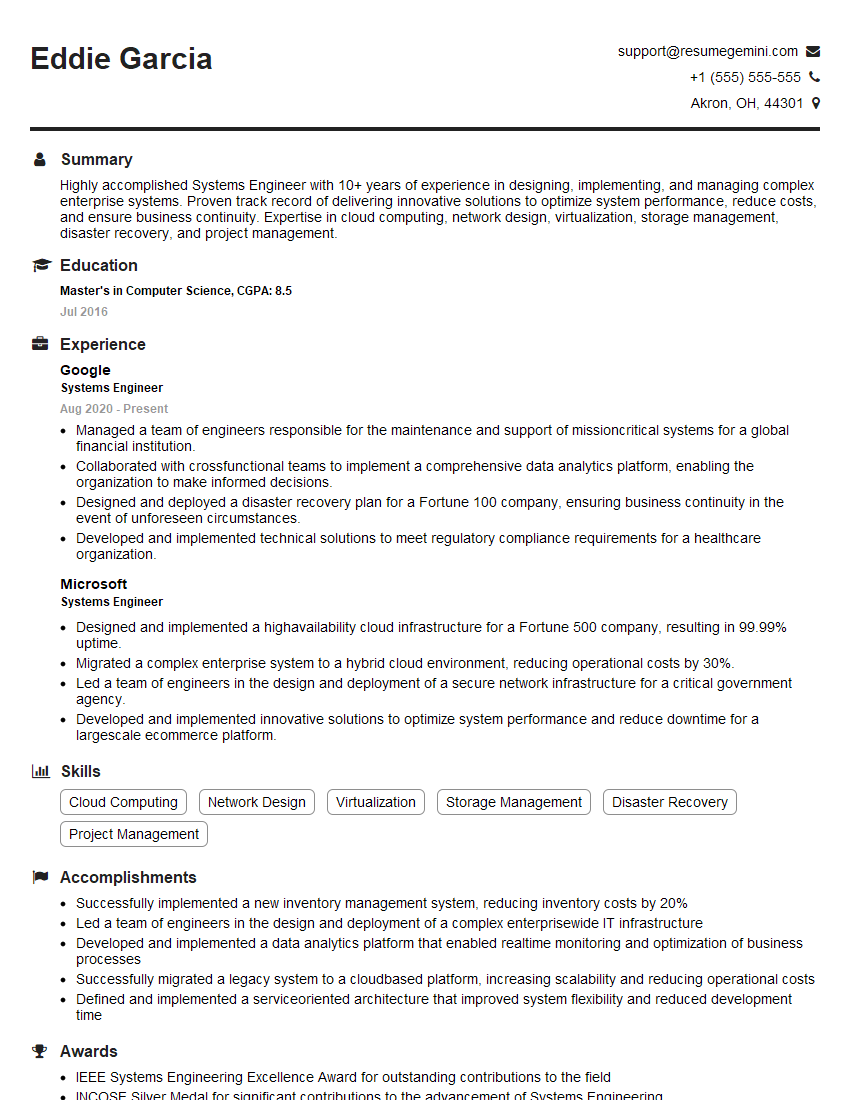
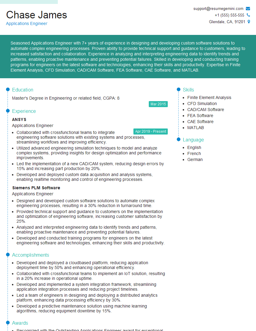
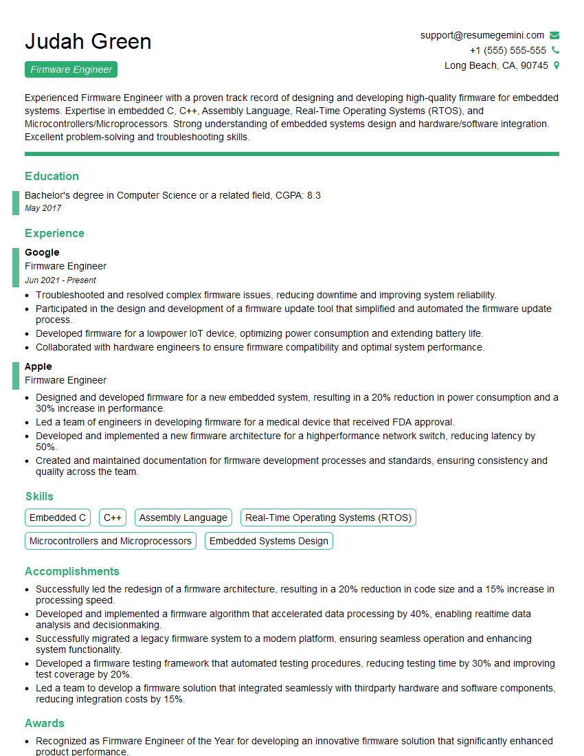
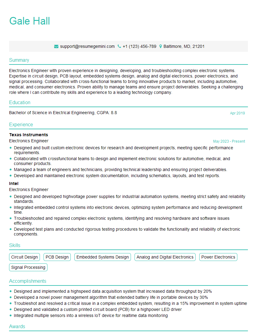
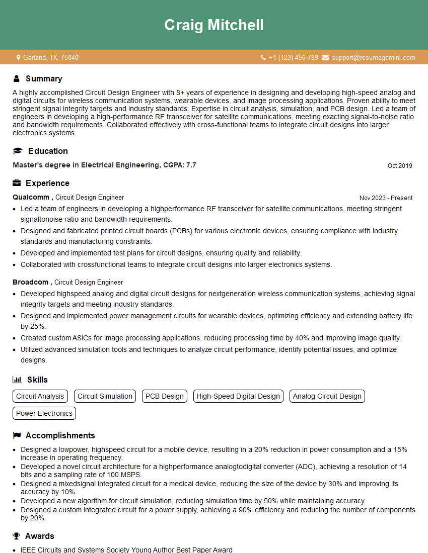
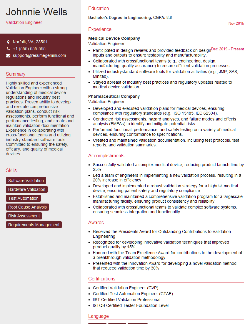
Mastering Electrical Engineering Design opens doors to exciting and rewarding careers in various industries. A strong foundation in these core concepts significantly enhances your job prospects and allows you to contribute meaningfully from day one. To maximize your chances of landing your dream role, it’s crucial to present your skills and experience effectively. Creating an ATS-friendly resume is key to getting your application noticed by recruiters. ResumeGemini can help you build a professional and impactful resume that showcases your expertise in Electrical Engineering Design. Examples of resumes tailored to this field are available to guide you through the process.
Explore more articles
Users Rating of Our Blogs
Share Your Experience
We value your feedback! Please rate our content and share your thoughts (optional).
What Readers Say About Our Blog
This was kind of a unique content I found around the specialized skills. Very helpful questions and good detailed answers.
Very Helpful blog, thank you Interviewgemini team.
