Unlock your full potential by mastering the most common Design and Fabrication interview questions. This blog offers a deep dive into the critical topics, ensuring you’re not only prepared to answer but to excel. With these insights, you’ll approach your interview with clarity and confidence.
Questions Asked in Design and Fabrication Interview
Q 1. Explain your experience with CAD software (AutoCAD, SolidWorks, etc.).
My experience with CAD software is extensive, encompassing both 2D and 3D modeling. I’m highly proficient in AutoCAD, a cornerstone for 2D drafting and detailed design, particularly for architectural and mechanical drawings. I’ve used it extensively for creating precise blueprints, schematics, and detailed drawings for various projects, from designing custom jigs and fixtures to generating manufacturing documentation. SolidWorks, on the other hand, is my primary tool for 3D modeling. Its powerful features allow for complex part design, assembly modeling, and simulation. I’ve used it to design everything from intricate mechanical components to full product assemblies, leveraging its capabilities for creating realistic renderings and performing stress analysis.
For example, in a recent project involving the design of a robotic arm, I used SolidWorks to model each individual component, simulate its movement and load bearing capacity, and then assemble the parts virtually to ensure proper functionality before physical fabrication. This significantly reduced potential errors and shortened the development cycle.
Furthermore, I have experience with other CAD packages like Fusion 360, which offers a streamlined workflow ideal for smaller projects and rapid prototyping. My experience extends to creating manufacturing drawings, including detailed dimensions, tolerances, and material specifications, ensuring seamless communication between the design and manufacturing teams.
Q 2. Describe your experience with CAM software (Mastercam, Fusion 360, etc.).
My CAM software experience focuses primarily on Mastercam and Fusion 360. Mastercam is a robust system particularly well-suited for CNC machining, allowing for the creation of sophisticated toolpaths for milling, turning, and other machining processes. I’ve used it to generate efficient and optimized toolpaths for various materials and geometries, minimizing machining time and maximizing surface finish. Fusion 360’s CAM capabilities provide a more integrated approach, allowing for direct translation from CAD models to toolpaths, which streamlines the entire design and fabrication workflow.
For instance, I recently used Mastercam to program a CNC mill to create a complex mold for a plastic part. The software’s ability to handle intricate geometries and generate collision-free toolpaths was crucial in achieving the required precision and surface finish. Similarly, I’ve leveraged Fusion 360’s CAM module for smaller projects where rapid prototyping is key; its ease of use allows for quick iteration and adjustments to the toolpaths.
My proficiency includes post-processor customization, enabling me to adapt the CAM software to work seamlessly with different CNC machines and control systems. Understanding the limitations of the machines and optimising toolpaths is paramount for achieving quality results efficiently.
Q 3. What are the different types of manufacturing processes you are familiar with?
My experience encompasses a wide range of manufacturing processes, both subtractive and additive. Subtractive processes include:
- CNC Machining (Milling and Turning): This is my area of expertise, involving the removal of material to create the desired shape. I’m proficient in various machining operations like face milling, end milling, drilling, and turning.
- Sheet Metal Fabrication: This includes processes like shearing, punching, bending, and welding to form sheet metal components.
- Casting (sand casting, investment casting): I understand the principles and limitations of different casting methods for creating complex shapes.
Additive processes include:
- 3D Printing (FDM, SLA, SLS): I have experience with different 3D printing technologies, selecting the appropriate method based on the material, part geometry, and required accuracy.
I also have familiarity with other processes like injection molding, which I’ve employed in projects requiring high-volume production of plastic parts. My understanding extends to selecting the appropriate manufacturing process based on factors such as part geometry, material properties, required tolerances, and production volume.
Q 4. Explain the differences between subtractive and additive manufacturing.
Subtractive and additive manufacturing represent fundamentally different approaches to creating parts. Subtractive manufacturing, such as CNC machining, begins with a larger block of material and removes material to achieve the final shape. Think of a sculptor chiseling away at a block of marble – the final product is what remains after material is removed.
Additive manufacturing, or 3D printing, works in the opposite way. It builds up the part layer by layer, adding material until the final design is complete. Imagine constructing a building brick by brick – the final structure is the accumulation of many individual pieces.
The key differences lie in the material usage (subtractive is inherently wasteful), the complexity of shapes achievable (additive excels at intricate geometries), the level of surface finish (additive often requires post-processing), and the production volume (subtractive is generally better for high-volume production).
Q 5. Describe your experience with CNC machining.
My experience with CNC machining spans several years and encompasses various machine types, including 3-axis and 5-axis milling machines, as well as lathe machines. I’m proficient in programming CNC machines using CAM software, setting up tooling, performing machining operations, and ensuring consistent part quality. This includes tasks like fixture design and part clamping to guarantee accurate machining. My experience includes working with a wide range of materials, including aluminum, steel, plastics, and composites.
A memorable project involved machining a complex titanium part for a medical device. The challenge was achieving tight tolerances and a smooth surface finish on a difficult-to-machine material. Through careful toolpath optimization, selection of appropriate cutting parameters, and meticulous attention to detail during the machining process, we successfully produced parts that met the stringent requirements.
Q 6. What are your troubleshooting skills related to CNC machines?
My troubleshooting skills related to CNC machines are comprehensive. I approach troubleshooting systematically, employing a combination of experience-based intuition and a methodical process. My approach involves:
- Identifying the problem: This includes carefully analyzing the error messages, observing the machine’s behavior, and examining the machined part for defects.
- Checking the obvious: This might involve verifying the correct tool selection, checking for tool wear or breakage, ensuring proper workpiece clamping, and verifying the coolant system is functioning.
- Systematically eliminating possibilities: I’ll check the control program for errors, verify the machine’s parameters (spindle speed, feed rate), inspect the machine’s mechanical components (for looseness or damage), and even check the machine’s electrical connections.
- Using diagnostic tools: This might include utilizing the machine’s built-in diagnostics, checking the program’s logic, or even consulting the machine’s manual.
For example, if a part shows inconsistent machining, I would systematically check the toolpath, the condition of the cutting tool, the workpiece’s setup, and the machine’s spindle speed and feed rates. I rarely jump to conclusions and instead systematically work through potential causes until the root problem is identified and resolved.
Q 7. How do you ensure dimensional accuracy in fabrication?
Ensuring dimensional accuracy in fabrication is crucial for the functionality and reliability of any product. My approach involves a multi-faceted strategy that begins at the design stage and continues throughout the entire manufacturing process.
- Precise CAD Modeling: Using accurate dimensions, tolerances, and appropriate design for manufacturability (DFM) principles are crucial from the start. This includes considering material shrinkage and distortion during manufacturing.
- CAM Programming and Toolpath Optimization: Precisely programmed toolpaths are critical for producing accurate parts. Proper selection of cutting tools and optimization of cutting parameters are essential to minimize errors.
- Accurate Machine Setup and Calibration: Regular calibration and maintenance of CNC machines are vital to ensure consistent accuracy. Workpiece fixturing is crucial for precise alignment and stability during machining.
- Quality Control Measures: This involves using measuring instruments (calipers, micrometers, CMM) to verify dimensions throughout the process and implementing statistical process control (SPC) to monitor and track dimensional accuracy.
- Material Selection: Choosing materials with appropriate properties for the application and considering their potential for deformation is paramount.
Regular inspection and verification ensure that the manufactured parts conform to the design specifications, minimizing errors and waste. For high-precision parts, I would typically utilize a Coordinate Measuring Machine (CMM) for accurate dimensional verification.
Q 8. Explain your experience with welding techniques.
My experience with welding techniques spans over 10 years, encompassing various processes including Gas Metal Arc Welding (GMAW), Gas Tungsten Arc Welding (GTAW), and Shielded Metal Arc Welding (SMAW). I’m proficient in selecting the appropriate welding process based on material type, thickness, and desired joint quality. For instance, I’ve used GMAW extensively for high-volume production runs of mild steel components, appreciating its speed and efficiency. For critical applications requiring superior weld aesthetics and precision, such as stainless steel piping, GTAW was my preferred method. SMAW, with its portability, proved invaluable in field repairs where access to power sources was limited. My skills extend to setting up and calibrating welding equipment, performing pre-weld inspections, and adhering strictly to safety protocols.
I’ve also worked with specialized welding techniques like pulse welding (for precise control over bead width and penetration) and submerged arc welding (SAW) for high deposition rates on thick sections. Each technique necessitates a unique skillset and understanding of parameters such as amperage, voltage, travel speed, and shielding gas composition. I continually stay updated on industry best practices and advancements in welding technology through professional development courses and industry publications.
Q 9. What are the common welding defects and how to prevent them?
Common welding defects can significantly compromise the structural integrity and aesthetics of a weld. Some frequently encountered defects include:
- Porosity: The presence of gas pockets within the weld metal, often caused by improper shielding gas coverage or contaminated materials. Prevention involves ensuring proper shielding, using clean materials, and adjusting welding parameters.
- Undercutting: A groove melted into the base material at the edge of the weld, reducing strength and creating stress points. Correcting the travel speed, amperage, and arc length can help prevent undercutting.
- Lack of Fusion: Incomplete melting and bonding between the weld metal and the base material. This stems from inadequate heat input or surface contamination; thorough surface preparation and appropriate welding parameters are crucial.
- Cracking: Fractures within the weld caused by rapid cooling, improper preheating, or metallurgical incompatibility. Proper preheating, selecting suitable filler materials, and controlled cooling rates are necessary to mitigate cracking.
- Slag Inclusions: Trapped pieces of slag (the molten by-product of welding) in the weld metal, weakening its structure. This is preventable with proper cleaning techniques and electrode selection.
Preventing these defects requires meticulous attention to detail throughout the welding process. This includes proper pre-weld preparation (cleaning, grinding, and preheating as needed), appropriate selection of welding parameters and filler materials, consistent welding technique, and post-weld inspection using visual inspection, radiography, or other non-destructive testing (NDT) methods.
Q 10. Describe your experience with robotics in manufacturing.
My experience with robotics in manufacturing focuses primarily on their integration into automated welding processes. I’ve worked on projects involving the programming and operation of robotic welding systems using industry-standard software such as FANUC, ABB, and KUKA controllers. This involves creating and optimizing weld paths, adjusting robot parameters for different materials and thicknesses, and troubleshooting malfunctions.
For example, in one project, we automated a welding cell for the production of large steel frames. The robotic system significantly increased production efficiency, reduced labor costs, and improved weld consistency compared to manual welding. My role included designing the robot’s workspace, creating the welding programs using teach pendants and offline programming software, and monitoring the performance of the automated system to ensure it met the required quality and speed standards. Additionally, I’ve been involved in the selection and integration of peripheral equipment like material handling systems and vision systems to enhance the automation process. This experience encompasses the entire lifecycle of robotic integration, from design and programming through deployment and maintenance.
Q 11. Explain your understanding of tolerance and its importance in design and fabrication.
Tolerance in design and fabrication refers to the permissible variation from a specified dimension or geometry. It’s crucial because it defines the acceptable range of variation that still allows a part or assembly to function correctly. Imagine trying to assemble a puzzle where pieces are slightly different sizes – they wouldn’t fit together properly. Tolerances prevent that in manufacturing.
The importance of tolerance is multifaceted:
- Functionality: Proper tolerances ensure parts fit and function as intended. Too loose a tolerance can lead to looseness or excessive play, whereas too tight tolerances may cause interference or difficulty in assembly.
- Interchangeability: Tolerances enable mass production of parts, allowing them to be interchangeable without significant adjustments.
- Cost-effectiveness: Tight tolerances often increase manufacturing costs, requiring more precise machining or specialized equipment. Optimizing tolerances balances functionality with economic feasibility.
- Quality Control: Tolerances provide a standard against which to measure the quality of fabricated parts. Inspection procedures verify that parts fall within the specified tolerances.
Specifying tolerances involves understanding the manufacturing processes and the capabilities of the equipment. Geometric Dimensioning and Tolerancing (GD&T) is a standardized system used to clearly communicate tolerance requirements in engineering drawings, preventing misinterpretations and ensuring consistency.
Q 12. How do you manage project timelines and budgets in a design and fabrication setting?
Managing project timelines and budgets in design and fabrication requires a structured approach. I typically employ a Work Breakdown Structure (WBS) to break down the project into smaller, manageable tasks. Each task is assigned a duration and cost estimate, allowing for accurate overall project scheduling and budgeting. Software like MS Project or Primavera P6 are used to track progress, identify potential delays, and manage resources.
Regular project meetings are held to review progress against the schedule and budget, identify any deviations, and take corrective actions. This includes close communication with clients and stakeholders to manage expectations and address any emerging challenges. Risk assessment is an integral part of the process, anticipating potential issues (e.g., material delays, equipment malfunctions) and developing contingency plans. Contingency reserves are included in the budget to handle unforeseen expenses. Continuous monitoring and adjustment ensure the project stays on track and within budget.
Q 13. How do you handle design changes during the fabrication process?
Design changes during fabrication are a common occurrence and necessitate a careful and systematic approach to minimize disruptions and added costs. The first step is to thoroughly evaluate the impact of the change on the overall project. This involves assessing the required modifications to existing components, the potential need for additional materials or labor, and the impact on the project timeline.
A formal change request process is essential, documenting the proposed changes, their rationale, and the estimated impact on the schedule and budget. This request is reviewed and approved by relevant stakeholders. A revised design is then produced, and updated drawings and specifications are distributed. Careful planning and coordination with the fabrication team are critical to implementing the changes efficiently and minimizing any rework. Detailed communication throughout the process is key to ensuring everyone is informed and aware of the changes and their consequences.
Q 14. Describe your experience with quality control procedures.
Quality control procedures are integral throughout the design and fabrication process. They start with careful material selection and inspection to ensure compliance with specified standards. During fabrication, regular in-process inspections are performed to verify that the work conforms to the drawings and specifications. This might involve visual inspections, dimensional checks using measuring instruments, and destructive or non-destructive testing (NDT) methods like ultrasonic testing or radiography for critical components.
A documented quality control plan outlines all inspection points and acceptance criteria. Data from inspections is recorded and analyzed to identify trends and potential areas for improvement. Non-conforming parts are promptly identified and dealt with, either through rework, repair, or rejection. Final inspection before delivery ensures that the finished product meets all quality requirements. ISO 9001 compliance is a standard practice to ensure a robust quality management system is in place.
Q 15. What are your preferred materials for different fabrication applications?
Material selection is crucial in design and fabrication. My choice depends heavily on the application’s requirements, balancing properties like strength, cost, aesthetics, and sustainability.
- For high-strength applications, like structural components, I often favor materials like aluminum alloys (for their lightweight strength), steel (for high tensile strength), or carbon fiber composites (for exceptional strength-to-weight ratios). For example, designing a drone frame would necessitate a lightweight yet strong material like carbon fiber.
- For aesthetically pleasing projects, I might choose hardwoods like walnut or maple for their rich grain, or plastics like acrylic for their vibrant colors and ease of machining. Designing a high-end furniture piece might require the use of exotic hardwoods.
- For cost-sensitive projects, I’d consider materials like mild steel or common plastics like ABS. A simple shelving unit could utilize readily available and affordable materials like particle board or melamine.
- For environmentally conscious projects, I prioritize recycled materials or sustainably sourced options like bamboo or reclaimed wood. Designing a bio-degradable plant pot would require eco-friendly materials such as cornstarch-based plastics.
Ultimately, the best material is the one that best meets the specific needs of the project while considering all relevant factors.
Career Expert Tips:
- Ace those interviews! Prepare effectively by reviewing the Top 50 Most Common Interview Questions on ResumeGemini.
- Navigate your job search with confidence! Explore a wide range of Career Tips on ResumeGemini. Learn about common challenges and recommendations to overcome them.
- Craft the perfect resume! Master the Art of Resume Writing with ResumeGemini’s guide. Showcase your unique qualifications and achievements effectively.
- Don’t miss out on holiday savings! Build your dream resume with ResumeGemini’s ATS optimized templates.
Q 16. Explain your understanding of material properties and their impact on design.
Understanding material properties is fundamental to successful design. These properties directly influence a design’s functionality, durability, and overall performance. For instance:
- Tensile strength (ability to withstand pulling forces) is vital for designing load-bearing structures. A bridge, for instance, requires materials with extremely high tensile strength.
- Compressive strength (ability to withstand squeezing forces) is important for elements subjected to compression. Think of the pillars supporting a building.
- Yield strength (stress at which a material begins to deform permanently) helps determine the design’s ability to withstand loads without permanent damage. A car bumper, for example, needs to have a specific yield strength to absorb impact without deforming beyond repair.
- Hardness (resistance to scratching or indentation) determines the material’s resistance to wear and tear. A cutting tool needs to be exceptionally hard to maintain its sharpness.
- Ductility (ability to deform plastically under tensile stress) is important for materials requiring forming processes, like bending or drawing. Metal sheets used in automobile bodies need to be ductile enough to be shaped during manufacturing.
- Thermal conductivity (ability to conduct heat) influences design choices for heat dissipation in electronics or heat exchangers. Designing a heat sink requires a material with high thermal conductivity.
Ignoring material properties can lead to catastrophic failures. A poorly chosen material with inadequate strength could lead to structural collapse, while a material with poor thermal conductivity could cause overheating and component failure. Therefore, careful material selection and understanding of their properties are crucial for a robust and functional design.
Q 17. How do you ensure the safety of yourself and others during fabrication?
Safety is paramount in fabrication. I meticulously follow safety protocols at every stage, from planning to cleanup. This includes:
- Proper Personal Protective Equipment (PPE): Always wearing safety glasses, hearing protection, respirators (when necessary), gloves, and appropriate clothing for the task. For example, using a respirator when working with chemical fumes or fine dust particles.
- Safe Tool Operation: Thorough understanding and proper use of all tools and machinery, including regular maintenance and inspection. For example, ensuring machine guards are in place and functioning correctly before operation.
- Workshop Organization: Maintaining a clean and organized workspace to prevent accidents caused by tripping hazards or cluttered areas. Regularly decluttering the work area minimizes the risk of accidents.
- Risk Assessment: Identifying potential hazards before starting any project and implementing preventive measures. Identifying potential risks associated with a particular project and taking necessary preventative steps is critical.
- Emergency Procedures: Knowing the location of emergency equipment (fire extinguishers, first-aid kit) and having a plan in place for emergencies. Regular training sessions should be conducted to ensure team members understand emergency response procedures.
Safety isn’t just a set of rules; it’s a mindset. I consistently prioritize safety to protect myself and others, making it an integral part of my fabrication process.
Q 18. What are your preferred methods for prototyping?
My prototyping methods depend on the project’s complexity and requirements. I often utilize a combination of techniques:
- Sketching and 2D CAD Modeling: Initial concepts are usually sketched, followed by 2D CAD modeling for detailed planning and documentation.
- 3D Modeling (CAD): Creating detailed 3D models allows for virtual testing and analysis before physical fabrication.
- Rapid Prototyping Techniques: For quick iterations and functional testing, I often employ techniques like 3D printing (various methods depending on material and precision needs), laser cutting (for flat parts from sheet materials), and CNC machining (for more precise parts from various materials).
- Hand-built Prototypes: For simpler designs or exploring design concepts early on, hand-building prototypes using readily available materials (wood, cardboard, etc.) can be effective.
I iterate through prototypes, refining the design based on testing and feedback. This iterative process ensures that the final product meets the intended functionality and aesthetics.
Q 19. Explain your experience with different types of 3D printing.
I have experience with several 3D printing technologies, each with its strengths and weaknesses:
- Fused Deposition Modeling (FDM): Cost-effective for prototyping, using a thermoplastic filament melted and extruded layer by layer. Suitable for functional prototypes but limited in detail and surface finish. I’ve used it extensively for creating functional parts like housings and jigs.
- Stereolithography (SLA): High-resolution printing using a photopolymer resin cured by UV light. Provides excellent detail and surface finish, ideal for creating accurate models and intricate parts. I’ve utilized SLA for creating precise molds and detailed architectural models.
- Selective Laser Sintering (SLS): Uses a laser to fuse powdered materials (plastics, metals) layer by layer. Suitable for creating strong and durable prototypes, even complex geometries. It’s been useful for creating robust functional parts with high strength requirements.
- Multi Jet Fusion (MJF): A high-speed printing technology using powdered materials. Offers high speed, fine detail, and good strength, ideal for larger-scale production. I’ve used this for short run production of durable parts.
Choosing the right 3D printing method depends on the design complexity, required material properties, budget, and desired surface finish. My experience allows me to select the best option for each project.
Q 20. Describe your experience with reverse engineering.
Reverse engineering involves taking apart an existing product to understand its design, function, and manufacturing processes. My experience with reverse engineering includes:
- Disassembly and Documentation: Carefully disassembling a product, documenting its components, and capturing measurements and specifications using calipers, micrometers, and 3D scanners.
- 3D Scanning and Modeling: Creating a 3D model of the product using 3D scanning technology, enabling detailed analysis and modification of the design.
- Material Analysis: Identifying the materials used in the product to understand its properties and manufacturing techniques.
- Functional Analysis: Understanding how each component works and how they interact to achieve the overall functionality of the product.
I’ve used reverse engineering for various purposes, including creating replacement parts, improving existing designs, and understanding the competitive landscape. For instance, I once reverse-engineered a broken electronic device to identify the faulty component, allowing for a cost-effective repair instead of complete replacement.
Q 21. How do you approach problem-solving in a design and fabrication context?
My approach to problem-solving in design and fabrication is iterative and methodical. It typically involves:
- Clearly Defining the Problem: Thoroughly understanding the project goals, constraints, and requirements. This includes defining the problem in clear, measurable terms and focusing on the specific challenges.
- Brainstorming and Ideation: Generating multiple potential solutions through brainstorming sessions, considering various design approaches and material choices.
- Prototyping and Testing: Creating physical or virtual prototypes to test the feasibility and functionality of different solutions.
- Analysis and Iteration: Analyzing the results of testing, identifying shortcomings, and iterating on the design until a satisfactory solution is achieved.
- Documentation and Communication: Maintaining thorough documentation of the design process, including design choices, test results, and modifications, for future reference and collaboration.
For example, when designing a custom-fit prosthetic, I’d begin by taking precise measurements of the patient’s limb. Then, I would create a 3D model, use prototyping to verify the fit, and finally fabricate a final prosthetic, iterating on the design if required. This methodical approach allows for optimization and improvement throughout the process.
Q 22. How do you collaborate with other engineers and technicians?
Collaboration is paramount in design and fabrication. I thrive in team environments, leveraging each member’s unique skills. My approach involves clear communication, active listening, and a proactive attitude. I believe in establishing a shared understanding of project goals from the outset, utilizing tools like regular project meetings, shared online platforms (like collaborative design software or project management tools), and open communication channels to ensure everyone is on the same page. For instance, on a recent project involving a complex robotic arm, I collaborated closely with electrical engineers to ensure seamless integration of the control system and mechanical design. We used daily stand-up meetings to discuss progress and address any arising issues promptly. This collaborative approach ensured the project was completed on time and within budget.
- Clear Communication: Regular updates and constructive feedback are key.
- Shared Platforms: Utilizing collaborative design software enhances efficiency and transparency.
- Active Listening: Understanding diverse perspectives leads to better solutions.
Q 23. Explain your experience with technical documentation.
Technical documentation is critical for ensuring project success and maintainability. My experience encompasses creating comprehensive documentation including detailed drawings (using CAD software like SolidWorks or AutoCAD), assembly instructions, bill of materials (BOMs), and test reports. I’m proficient in creating documentation that adheres to industry standards and best practices. For example, I’ve prepared detailed fabrication drawings for a custom-designed wind turbine component, complete with tolerances, material specifications, and surface finish requirements. These drawings were used by the fabrication team to produce the component accurately and efficiently. Furthermore, I am comfortable using various documentation formats, from PDFs and spreadsheets to specialized engineering databases. Thorough and well-organized documentation is essential not just for the current project but for future maintenance, upgrades, or even potential replication.
Q 24. How do you stay up-to-date with advancements in design and fabrication technologies?
Staying current in design and fabrication requires a multi-pronged approach. I actively participate in industry conferences and webinars, attend workshops on new software and techniques, and subscribe to relevant industry publications and journals. I also leverage online resources, including professional organizations’ websites and online learning platforms, to access the latest research and best practices. For example, I recently completed a course on additive manufacturing (3D printing) techniques, significantly enhancing my understanding of this rapidly evolving field and broadening my design possibilities. Continuous learning is crucial to remain competitive and to adopt innovative solutions in this rapidly evolving field.
Q 25. What are your strengths and weaknesses related to design and fabrication?
My strengths lie in my problem-solving abilities, my meticulous attention to detail, and my proficiency in various CAD software. I’m also a strong communicator and team player. However, like everyone, I have areas for improvement. One area I’m actively working on is further expanding my experience with advanced materials and their fabrication processes, particularly in the area of composite materials. While I have a solid foundation, I believe continued learning in this area will enhance my expertise further.
Q 26. Describe a challenging project you worked on and how you overcame the challenges.
One challenging project involved designing and fabricating a custom jig for a complex aerospace component. The component had intricate geometries and tight tolerances, making the jig design exceptionally demanding. The initial design proved difficult to fabricate due to unforeseen complexities in the manufacturing process. To overcome this, I employed a collaborative approach, working closely with the fabrication team to identify the problem areas. We then utilized Finite Element Analysis (FEA) to simulate the jig’s performance under load, which helped identify and correct design flaws. Through iterative design and rigorous testing, we successfully produced a jig that met all specifications, allowing for efficient and accurate component fabrication. This project reinforced the importance of iterative design, collaborative teamwork, and leveraging advanced simulation tools to address challenging fabrication issues.
Q 27. What are your salary expectations?
My salary expectations are commensurate with my experience and skills, and are in line with the industry standard for a senior-level design and fabrication engineer with my qualifications. I am open to discussing this further based on the specifics of the role and compensation package offered.
Q 28. Do you have any questions for me?
I have a few questions. First, could you elaborate on the specific technologies and software used within your company? Second, what are the typical project timelines and what opportunities exist for professional development and advancement within the company? Finally, what is the team dynamic like and what opportunities are there for collaboration and knowledge sharing?
Key Topics to Learn for Design and Fabrication Interview
- CAD Software Proficiency: Mastering software like SolidWorks, AutoCAD, or Fusion 360 is crucial. Focus on demonstrating your skills in 3D modeling, drafting, and design optimization.
- Manufacturing Processes: Understand various fabrication techniques like machining (milling, turning, etc.), additive manufacturing (3D printing), casting, and welding. Be prepared to discuss their applications and limitations.
- Material Science Fundamentals: Demonstrate knowledge of material properties (strength, ductility, etc.) and their selection based on design requirements and manufacturing processes. This includes understanding different material types (metals, plastics, composites).
- Design for Manufacturing (DFM): Showcase your ability to design parts and assemblies considering manufacturing constraints, costs, and efficiency. Be ready to discuss how design choices impact the fabrication process.
- Tolerance Analysis and Control: Understand the importance of tolerances and how they affect part functionality and assembly. Be prepared to discuss methods for controlling and minimizing tolerances.
- Problem-Solving and Troubleshooting: Highlight your ability to identify and solve problems during the design and fabrication process. Use examples to illustrate your analytical and critical thinking skills.
- Quality Control and Inspection: Demonstrate familiarity with quality control methods and inspection techniques used to ensure the quality and accuracy of fabricated parts.
- Project Management Basics: Showcase your experience in managing projects, including planning, scheduling, and resource allocation, within the context of design and fabrication.
Next Steps
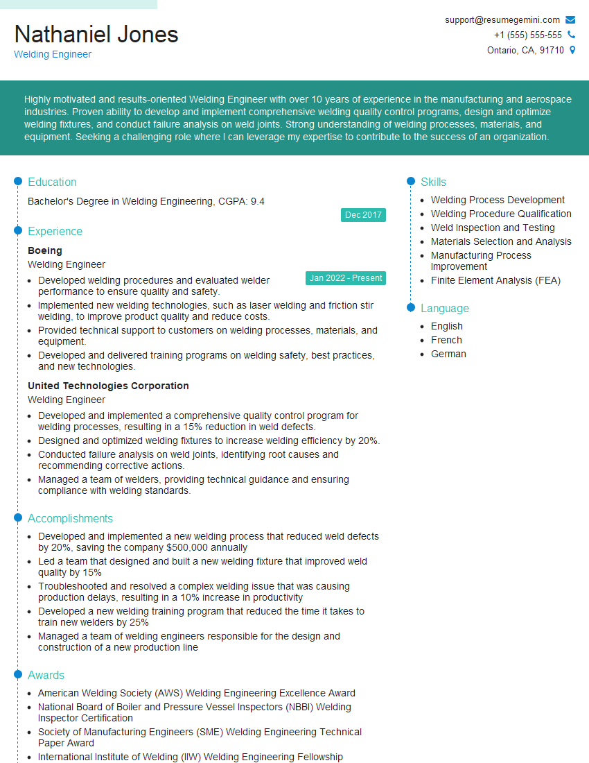
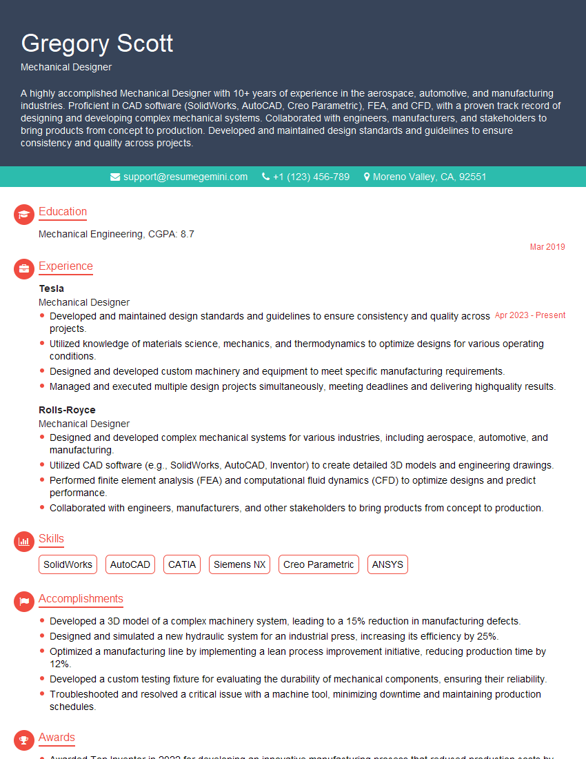
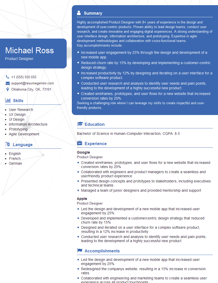
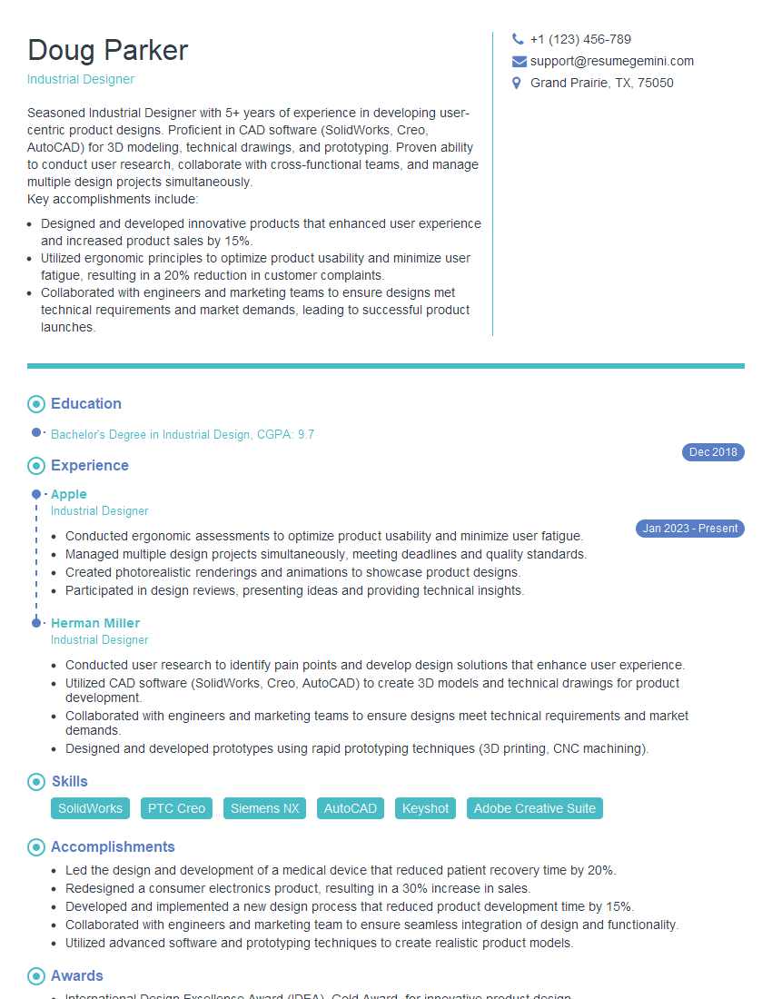
Mastering Design and Fabrication opens doors to exciting and rewarding careers in diverse industries. A strong foundation in these areas is vital for career growth and advancement. To maximize your job prospects, create an ATS-friendly resume that effectively showcases your skills and experience. ResumeGemini is a trusted resource for building professional and impactful resumes. Leverage its tools and resources to create a resume that highlights your unique qualifications. Examples of resumes tailored to Design and Fabrication are available within ResumeGemini to help guide your process.
Explore more articles
Users Rating of Our Blogs
Share Your Experience
We value your feedback! Please rate our content and share your thoughts (optional).
What Readers Say About Our Blog
This was kind of a unique content I found around the specialized skills. Very helpful questions and good detailed answers.
Very Helpful blog, thank you Interviewgemini team.
