The thought of an interview can be nerve-wracking, but the right preparation can make all the difference. Explore this comprehensive guide to Electrical and Mechanical Equipment interview questions and gain the confidence you need to showcase your abilities and secure the role.
Questions Asked in Electrical and Mechanical Equipment Interview
Q 1. Explain the difference between AC and DC electricity.
The fundamental difference between AC (Alternating Current) and DC (Direct Current) electricity lies in the direction of electron flow. In DC, electrons flow consistently in one direction, like a river flowing downstream. This is the type of electricity produced by batteries. In AC, the direction of electron flow reverses periodically, oscillating back and forth, similar to a wave in the ocean. This cyclical change is typically at a specific frequency, such as 50Hz or 60Hz depending on the geographical location.
Think of it this way: a battery provides DC power; your home’s electrical outlets provide AC power. AC is far more efficient for long-distance transmission because its voltage can be easily stepped up and down using transformers, minimizing energy loss. DC, while simpler in its nature, faces greater challenges in efficient transmission over long distances.
Q 2. Describe the function of a circuit breaker.
A circuit breaker is a safety device designed to protect electrical circuits from damage caused by overcurrent, short circuits, or ground faults. Essentially, it acts as an automatic switch that interrupts the flow of electricity when a dangerous situation arises. Imagine it as a pressure relief valve in a boiler – preventing catastrophic failure.
When the current exceeds a pre-determined threshold, an internal mechanism triggers, quickly opening the circuit and cutting off the power. This prevents overheating of wires, potential fires, and damage to connected equipment. Circuit breakers are crucial components in electrical systems, ensuring both safety and reliability.
There are various types, including thermal magnetic circuit breakers that combine both thermal and magnetic tripping mechanisms for diverse protection. They’re essential for household wiring, industrial machinery, and countless other applications.
Q 3. What are the common types of motors and their applications?
There’s a wide variety of electric motors, each suited to different applications. Some common types include:
- DC Motors: These are simple motors using direct current. They are easily controlled, offering precise speed regulation, which makes them suitable for applications like robotics and electric vehicles. However, they require commutators which can be a source of wear and tear.
- AC Induction Motors: These are robust and widely used in industrial applications because of their simple design, low maintenance requirements, and high efficiency. The most common is the three-phase induction motor (detailed in the next question). They’re used in everything from pumps and fans to conveyor belts.
- AC Synchronous Motors: These motors run at a constant speed, synchronized with the AC power frequency. They are often used in applications requiring precise speed control, such as clocks and timing mechanisms.
- Stepper Motors: Stepper motors rotate in precise increments, making them ideal for applications requiring accurate positioning, such as 3D printers and CNC machines.
- Servomotors: Servomotors provide high accuracy and speed control, often used in robotics, automation systems, and precision machinery.
The choice of motor depends entirely on factors such as required speed, torque, efficiency, cost, and the specific application needs.
Q 4. How does a three-phase motor work?
A three-phase motor operates using three separate AC power sources, each offset by 120 degrees in phase. These three phases generate a rotating magnetic field within the motor’s stator (stationary part). This rotating field interacts with the rotor (rotating part), inducing currents in the rotor windings, creating a magnetic field that aligns with the stator’s field. The continuous interaction between these magnetic fields causes the rotor to spin.
Think of it like this: imagine three magnets, equally spaced around a circle, each attracting and repelling a central magnet. As the stator’s magnetic field rotates, the rotor follows, resulting in continuous rotation. Three-phase motors are highly efficient, delivering high torque, and are extensively used in industrial settings due to their robust nature and reliable performance.
Q 5. Explain the principles of hydraulic systems.
Hydraulic systems utilize the power of pressurized liquids, typically oil, to transmit force and motion. They work on Pascal’s principle, which states that pressure applied to an enclosed fluid is transmitted undiminished to every portion of the fluid and to the walls of the containing vessel. This means a small force applied to a small area can generate a large force over a larger area by utilizing pressure amplification.
A typical hydraulic system consists of a pump, which pressurizes the oil; valves to control the flow and direction of the oil; actuators (cylinders or motors) that convert hydraulic pressure into mechanical force and motion; and a reservoir to hold the oil. They’re remarkably powerful and efficient for moving heavy loads, offering precise control, and are used in heavy machinery like excavators, cranes, and aircraft landing gear.
Q 6. Describe different types of bearings and their applications.
Bearings are crucial mechanical components that reduce friction between moving parts. Different types exist, each designed for specific applications:
- Ball Bearings: Use rolling balls to reduce friction, suitable for high speeds and light to moderate loads. Common in wheels, motors, and many rotating parts.
- Roller Bearings: Use cylindrical or tapered rollers, providing higher load-carrying capacity than ball bearings. Ideal for heavy-duty applications such as large machinery and vehicle axles.
- Sleeve Bearings (Journal Bearings): Use a lubricating fluid film between the shaft and the bearing to reduce friction. These are simpler and often cheaper but have lower load-carrying capacity and can be sensitive to lubrication.
- Thrust Bearings: Designed to handle axial loads (forces pushing or pulling along the shaft axis), commonly used in applications where the shaft is subject to significant axial forces.
The selection of bearing type depends on factors such as speed, load, operating environment, and required lifetime.
Q 7. What are the common causes of motor failure?
Motor failures can stem from various issues:
- Winding failures: Overheating, insulation breakdown, or short circuits in motor windings are common causes. This can be due to overloading, improper ventilation, or age.
- Bearing failure: Wear and tear, improper lubrication, or contamination can damage bearings, leading to increased friction, noise, and ultimately motor failure.
- Mechanical issues: Misalignment, imbalance, or excessive vibration can stress the motor components, causing premature wear and tear.
- Electrical issues: Voltage fluctuations, power surges, or incorrect wiring can damage motor components or lead to premature failure.
- Overheating: Excessive loads, blocked ventilation, or inadequate cooling can lead to overheating, damaging insulation and other motor components.
Regular maintenance, including inspection, lubrication, and vibration analysis, can significantly reduce the risk of motor failures.
Q 8. How do you troubleshoot a malfunctioning electrical circuit?
Troubleshooting a malfunctioning electrical circuit involves a systematic approach, combining safety precautions with logical deduction. It starts with assessing the situation, identifying the symptoms, and systematically eliminating potential causes.
- Safety First: Always de-energize the circuit before commencing any troubleshooting. Lockout/Tagout procedures are crucial to prevent accidental energization.
- Visual Inspection: Begin with a careful visual examination of all components, looking for obvious signs of damage like burnt wires, loose connections, or damaged components.
- Testing with Multimeter: A multimeter is your primary tool. You’ll use it to check voltage, current, and resistance at various points in the circuit. For instance, checking voltage at the breaker to confirm power supply, and voltage across the load to see if it is receiving power. If there’s no voltage at the load but power at the breaker, it means there’s a break in the line somewhere.
- Systematic Elimination: By systematically checking each component and section of the circuit, you will isolate the problem. Start at the power source and work your way to the load.
- Component Replacement: Once the faulty component is identified, replace it with a known good component and retest the circuit.
- Documentation: Throughout the process, keep detailed records of your findings, including measurements and any component replacements. This will help in future maintenance and troubleshooting.
Example: Imagine a faulty lighting circuit. After de-energizing, a visual inspection reveals a loose wire connection at the switch. Using a multimeter, we confirm no voltage at the light fixture. Tightening the connection restores power to the light.
Q 9. Explain the concept of power factor and its importance.
Power factor is the ratio of real power (kW) to apparent power (kVA) in an AC electrical system. It represents how efficiently electrical power is used. Ideally, it should be 1 (or 100%), meaning all the apparent power is used as real power. However, in many industrial settings, it’s less than 1 due to reactive loads (like motors and transformers).
Importance: A low power factor leads to several inefficiencies:
- Increased Current Draw: A low power factor requires a higher current to deliver the same amount of real power, leading to increased heating in wires and transformers, causing potential damage and shortening lifespan.
- Higher Energy Costs: Utility companies often charge penalties for low power factors because they have to supply more current than necessary.
- Reduced System Capacity: The higher currents resulting from low power factor reduce the capacity of the system to deliver real power.
Improving Power Factor: Power factor correction is done by adding capacitor banks to the system. These capacitors provide reactive power that compensates for the reactive power consumed by the inductive loads, thereby improving the power factor and reducing the current draw.
Example: A factory with many induction motors might have a power factor of 0.8. By installing power factor correction capacitors, the power factor could be improved to 0.95, leading to significant savings in energy costs and a more efficient system.
Q 10. Describe your experience with PLC programming.
I have extensive experience in PLC programming using various platforms such as Siemens TIA Portal, Rockwell Automation Studio 5000, and Allen-Bradley RSLogix 500. My expertise encompasses ladder logic, structured text, and function block programming.
I have designed and implemented PLC programs for numerous industrial automation projects, including:
- Conveyor Systems Control: Designing PLC programs to manage the speed, direction, and sequencing of multiple conveyors in a production line.
- Process Control: Creating PLC programs to monitor and control parameters like temperature, pressure, and flow rates in chemical processing plants and similar applications.
- Robotics Integration: Integrating PLCs with robotic systems to manage the sequence of actions performed by robots in an assembly line or other automated processes.
- SCADA Integration: Connecting PLCs to Supervisory Control and Data Acquisition (SCADA) systems for monitoring and controlling a broader range of processes.
My experience also includes troubleshooting and modifying existing PLC programs to address operational issues and improve efficiency. I’m familiar with communication protocols like Ethernet/IP, Modbus TCP, and Profibus.
Example: I once resolved a production bottleneck by optimizing the PLC program controlling a filling machine, improving throughput by 15% by adjusting the timing and sequencing of various operational steps.
Q 11. How do you perform preventative maintenance on electrical equipment?
Preventative maintenance on electrical equipment is crucial for ensuring its reliability, safety, and longevity. It involves regularly inspecting, cleaning, and testing equipment to identify and rectify potential problems before they lead to failures.
- Visual Inspection: Checking for loose connections, corrosion, overheating signs, damaged insulation, and any physical damage.
- Cleaning: Removing dust, dirt, and debris from electrical enclosures and components to improve cooling and prevent insulation breakdown.
- Testing: Using a multimeter to check voltage, current, and insulation resistance. Thermal imaging cameras can detect hotspots indicative of potential problems.
- Lubrication: Lubricating moving parts of electrical equipment like motors and switches to reduce wear and tear.
- Tightening Connections: Ensuring all connections are tight to prevent arcing and overheating.
- Calibration: Regularly calibrating sensors and instruments connected to the electrical equipment to maintain accuracy.
Example: A regular preventative maintenance schedule for a motor-driven pump would involve visually inspecting the motor and pump for any leaks or signs of damage, checking the motor bearings for wear, and verifying that the proper lubrication levels are maintained.
Implementing a detailed preventative maintenance schedule is key. This schedule should specify the frequency of each maintenance task based on the type of equipment, its operating conditions, and manufacturer’s recommendations.
Q 12. What are the safety procedures for working with high-voltage equipment?
Working with high-voltage equipment presents significant risks of electric shock, arc flash, and fire. Stringent safety procedures are paramount.
- Lockout/Tagout (LOTO): This is the most crucial step. Before any work is done, the power supply must be de-energized and locked out using a LOTO procedure to prevent accidental energization.
- Personal Protective Equipment (PPE): Appropriate PPE must always be worn, including insulated gloves, safety glasses, arc flash suits (where appropriate), and safety footwear.
- Grounding: Equipment must be properly grounded to prevent the buildup of static electricity and provide a path for fault currents.
- Trained Personnel: Only trained and authorized personnel with a deep understanding of high-voltage safety procedures should work on high-voltage equipment.
- Safe Working Distance: Maintaining a safe working distance from energized equipment is crucial. This distance varies depending on the voltage level.
- Emergency Procedures: A well-defined emergency plan must be in place, including procedures for dealing with electric shock and fire.
Example: Before working on a 480V panel, the circuit breaker must be locked out and tagged, and a qualified electrician must wear appropriate PPE, including arc flash protective clothing, insulated gloves, and safety glasses. They must also ensure that the panel is properly grounded before commencing any work.
Q 13. Explain the different types of sensors used in industrial automation.
Industrial automation relies heavily on a variety of sensors to monitor and control processes. These sensors can be categorized into several types:
- Proximity Sensors: Detect the presence of an object without physical contact. They come in various types, including inductive, capacitive, and photoelectric sensors.
- Temperature Sensors: Measure temperature using various methods, including thermocouples, RTDs (Resistance Temperature Detectors), and thermistors.
- Pressure Sensors: Measure pressure using various technologies, such as strain gauges, capacitive sensors, and piezoelectric sensors.
- Flow Sensors: Measure the flow rate of liquids or gases using methods like differential pressure, ultrasonic, or vortex shedding.
- Level Sensors: Measure the level of liquids or solids in a container, using ultrasonic, radar, or float sensors.
- Force Sensors: Measure force or weight using strain gauges or load cells.
- Position Sensors: Determine the position or angular displacement of an object, such as potentiometers, encoders, and LVDTs (Linear Variable Differential Transformers).
The choice of sensor depends on the specific application, the type of parameter being measured, and the required accuracy and range.
Example: A robotic arm in a manufacturing process uses proximity sensors to detect the presence of parts, pressure sensors to monitor the grip force, and position sensors to control its movements precisely.
Q 14. Describe your experience with CAD software.
I’m proficient in several CAD software packages, including AutoCAD, SolidWorks, and Inventor. My experience spans both 2D and 3D modeling, from creating basic drawings to developing complex assemblies.
I have used CAD software for:
- Designing Mechanical Components: Creating detailed 3D models of mechanical parts for manufacturing and assembly.
- Developing Electrical Schematics: Using CAD software to create accurate and detailed electrical schematics and diagrams for control systems and other electrical installations.
- Creating Factory Layouts: Designing the layout of industrial facilities, including equipment placement and material flow.
- Generating Manufacturing Drawings: Creating detailed 2D drawings for manufacturing processes, including dimensions, tolerances, and material specifications.
- Preparing Technical Documentation: Creating technical illustrations, assembly instructions, and other documentation using CAD software.
Example: In a recent project, I used SolidWorks to design a custom jig for automating a repetitive assembly task, resulting in increased production efficiency and reduced labor costs. I then used AutoCAD to generate the manufacturing drawings.
Q 15. How do you interpret engineering drawings?
Interpreting engineering drawings requires a systematic approach combining technical knowledge with visual acuity. It’s like reading a detailed instruction manual for a complex machine, but instead of words, it’s lines, symbols, and dimensions.
First, I identify the drawing type (e.g., assembly, detail, schematic). Then, I examine the title block for essential information like the drawing number, revision level, and scale. I systematically review the views (orthographic, isometric, sectional) to understand the object’s three-dimensional geometry. I meticulously analyze dimensions, tolerances, and material specifications. Symbols and annotations are deciphered using relevant standards (e.g., ASME Y14.5). I always look for any notes or callouts that might clarify ambiguous details. For electrical drawings, I pay close attention to circuit diagrams, wiring configurations, and component specifications.
For example, in a mechanical drawing of a pump, I’d examine the cross-sectional view to understand the impeller design and internal fluid flow path. The dimensions would inform me about the pump’s size and capacity. Material specifications would dictate its suitability for different fluids and operating conditions. In an electrical drawing of a motor control system, I would look for the wiring diagram and relay logic to understand how the system operates and interacts with other equipment.
Career Expert Tips:
- Ace those interviews! Prepare effectively by reviewing the Top 50 Most Common Interview Questions on ResumeGemini.
- Navigate your job search with confidence! Explore a wide range of Career Tips on ResumeGemini. Learn about common challenges and recommendations to overcome them.
- Craft the perfect resume! Master the Art of Resume Writing with ResumeGemini’s guide. Showcase your unique qualifications and achievements effectively.
- Don’t miss out on holiday savings! Build your dream resume with ResumeGemini’s ATS optimized templates.
Q 16. What are your troubleshooting skills for mechanical systems?
Troubleshooting mechanical systems is a detective process. It’s about systematically identifying the root cause of a malfunction, not just treating the symptoms. My approach involves a structured methodology:
- Gather Information: I start by understanding the nature of the problem – what isn’t working, when it started, and what conditions preceded the failure. I’d interview operators, review maintenance logs, and inspect the system visually.
- Visual Inspection: I carefully examine the system for obvious signs of damage, leaks, or wear. This might involve checking belts, bearings, seals, and couplings.
- Data Acquisition: I use appropriate tools like pressure gauges, thermometers, and vibration analyzers to gather quantitative data about the system’s performance. This step helps to pinpoint areas of concern.
- Component Testing: If necessary, I test individual components to isolate the faulty part. This might involve checking sensors, actuators, or control elements.
- Systematic Elimination: Based on the collected information and testing, I systematically eliminate possible causes until I locate the root problem. I’ll often draw a flowchart to visualize the process and trace the fault path.
- Repair or Replacement: Once the problem is identified, I’ll perform the necessary repairs or replace faulty components.
- Verification: After the repair, I thoroughly test the system to verify that it’s functioning correctly and prevent recurrence.
For instance, if a conveyor belt stops working, I might first check the motor power supply, then the motor itself, then the belt tension, and finally the drive system. Using a systematic approach significantly reduces downtime and avoids unnecessary part replacements.
Q 17. Explain the concept of torque and its significance in mechanical systems.
Torque is the rotational equivalent of force. Imagine you’re trying to loosen a bolt with a wrench – the harder you push (force) on the wrench’s handle, the more the bolt turns (rotation). Torque is the measure of this rotational force, specifically the force applied at a distance from the axis of rotation.
Mathematically, torque (τ) is calculated as: τ = F × r × sin(θ), where F is the force, r is the distance from the axis of rotation, and θ is the angle between the force vector and the lever arm. The significance of torque lies in its ability to cause rotational acceleration or deceleration in mechanical systems.
In mechanical systems, torque is crucial in various applications:
- Power Transmission: Engines and motors produce torque, which is then transmitted to shafts, gears, and other components to perform work. A high torque motor is required for heavy-duty applications.
- Rotational Motion Control: Torque is essential for controlling the speed and acceleration of rotating machinery like pumps, fans, and compressors.
- Fastening: Proper torque is vital when tightening bolts and nuts to ensure sufficient clamping force and prevent failure. Under-torquing leads to loosening, while over-torquing causes damage.
For example, in a car, the engine generates torque which is transferred through the transmission to the wheels to propel the vehicle. Insufficient torque would result in poor acceleration, while excessive torque could lead to component failure.
Q 18. Describe your experience with different types of pumps.
My experience encompasses a range of pump types, each suited for specific applications. I’m familiar with centrifugal pumps, positive displacement pumps (like gear pumps, piston pumps, and screw pumps), and specialized pumps like diaphragm pumps and peristaltic pumps.
Centrifugal pumps use rotational energy to increase the fluid’s velocity and pressure. They are suitable for high-flow, low-pressure applications like water supply systems. I’ve worked with various centrifugal pump designs, including single-stage and multi-stage configurations.
Positive displacement pumps move a fixed volume of fluid with each stroke or rotation. These pumps are well-suited for high-pressure, low-flow applications. I have hands-on experience with gear pumps in lubrication systems and piston pumps in hydraulic systems. I also have experience troubleshooting diaphragm pumps used in chemical handling and peristaltic pumps used in sensitive applications where pulsation needs to be minimized.
My experience also includes selecting appropriate pump types based on fluid properties, flow rate requirements, and pressure demands. I consider factors like viscosity, abrasiveness, temperature, and corrosiveness when choosing a pump for a particular application. I understand the importance of pump curves and system curves in determining the optimal operating point.
Q 19. How do you ensure the safety of electrical and mechanical systems?
Ensuring the safety of electrical and mechanical systems requires a multi-faceted approach that prioritizes hazard identification, risk assessment, and mitigation. It’s a continuous process of proactive measures and diligent adherence to safety protocols.
My safety practices start with a thorough risk assessment. I identify potential hazards associated with each system, such as electrical shocks, mechanical injuries, fire hazards, and process safety issues. I assess the likelihood and severity of these hazards and implement appropriate control measures. This might include implementing lockout/tagout procedures for maintenance, providing personal protective equipment (PPE), designing safety interlocks and emergency shutdowns, and adhering to relevant safety standards (e.g., OSHA, NFPA).
For electrical systems, I always follow safe work practices and use appropriate testing equipment to prevent electric shocks. Regular inspection and maintenance are crucial to identify and rectify potential hazards before they escalate. I ensure all electrical equipment is properly grounded and protected by appropriate circuit breakers and fuses.
For mechanical systems, I ensure proper guarding of moving parts, regular lubrication and inspection of components, and the use of safety devices like pressure relief valves and emergency stops. I make sure that equipment is operating within its design parameters. Training personnel on safe operating procedures and emergency response protocols is also a critical aspect of my approach.
Documentation of safety procedures, regular inspections, and maintenance logs are crucial for maintaining a safe working environment and ensuring compliance with regulations.
Q 20. What is your experience with robotics or automation systems?
I have significant experience with robotics and automation systems, primarily focused on industrial applications. My experience includes working with robotic arms for material handling, welding, and assembly processes. I understand the principles of robotic kinematics, control systems, and programming.
I’ve worked with various robotic platforms and control systems, including both traditional PLC-based systems and more modern, collaborative robots. My skills encompass programming robots using languages like RAPID (ABB) or KRL (KUKA), and integrating them into larger automation systems. I also have experience with vision systems used for robotic guidance and quality inspection.
In one project, I was responsible for integrating a robotic arm into a packaging line. This involved programming the robot to pick and place items onto a conveyor, ensuring accurate placement and high throughput. This required careful consideration of cycle times, robot reach, and error handling mechanisms.
My understanding extends to the safety aspects of robotic systems, including the implementation of safety scanners, light curtains, and emergency stops to protect workers from potential harm. I’m familiar with risk assessment methodologies specific to robotic systems.
Q 21. Explain your experience with SCADA systems.
Supervisory Control and Data Acquisition (SCADA) systems are critical for monitoring and controlling industrial processes remotely. My experience includes working with SCADA systems for various applications, including water treatment plants, power generation facilities, and manufacturing processes.
I’m proficient in configuring and troubleshooting SCADA systems, including HMI (Human-Machine Interface) design, data acquisition from various field devices, and alarm management. I’m familiar with various SCADA platforms and communication protocols like Modbus, Profibus, and Ethernet/IP.
My work with SCADA systems often involves integrating data from PLCs, RTUs (Remote Terminal Units), and other field devices. I’ve developed custom SCADA applications tailored to specific process requirements, including data visualization dashboards and customized reporting tools. I’m experienced in designing and implementing alarm systems that ensure timely notification of critical events.
For instance, in a water treatment plant project, I was involved in implementing a SCADA system to monitor water quality parameters, control pump operations, and manage the treatment process. This involved configuring the SCADA software, integrating with field sensors, and developing an HMI that provided operators with real-time insights into the plant’s status.
Data security and system redundancy are key considerations when working with SCADA systems, and I always incorporate those into the design and implementation processes.
Q 22. How do you handle emergency situations involving electrical or mechanical equipment?
Handling emergencies involving electrical or mechanical equipment requires a calm, systematic approach prioritizing safety. My first step is always to ensure the safety of myself and others. This involves immediately isolating the affected equipment – switching off power supplies, locking out and tagging out circuits as necessary, and evacuating personnel from the danger zone.
Following this, I assess the situation, identifying the nature and extent of the problem. For electrical issues, this might involve checking for signs of arcing, overheating, or damaged wiring. For mechanical failures, I’d look for broken parts, unusual vibrations, or leaks. Depending on the severity, I would then contact the relevant emergency services if necessary (fire department, paramedics etc.) or initiate the company’s established emergency response protocol. Finally, after securing the area, a thorough investigation will be conducted to identify the root cause and prevent recurrence.
For instance, during my time at Acme Manufacturing, a malfunctioning conveyor belt caused a near-miss incident. My immediate actions involved shutting down the power, securing the area, and then conducting a thorough inspection revealing a worn-out bearing as the root cause. We quickly replaced the bearing, implemented a preventative maintenance schedule, and updated safety procedures to prevent future occurrences.
Q 23. Describe your experience with root cause analysis of equipment failures.
Root cause analysis (RCA) is crucial for preventing equipment failures. My approach involves using a structured methodology, often the ‘5 Whys’ technique or a more formal Fishbone diagram (Ishikawa diagram). I start by clearly defining the problem. Then, I systematically investigate the contributing factors by repeatedly asking ‘why’ until the root cause is identified. This requires careful observation, data analysis (including maintenance logs and historical data), and often, collaboration with other engineers and technicians.
For example, during a recurring pump failure at a water treatment plant, the initial symptom was reduced water flow. Using the 5 Whys, we discovered: 1. Low flow rate. 2. Pump inefficiency. 3. Worn impeller. 4. Insufficient lubrication. 5. Inadequate maintenance schedule. Therefore, the root cause was identified as the inadequate maintenance schedule. Implementing a more robust maintenance program solved the problem permanently.
Q 24. What are your skills in using diagnostic tools for electrical and mechanical systems?
I’m proficient in using a variety of diagnostic tools for both electrical and mechanical systems. For electrical systems, I use multimeters (both digital and analog), oscilloscopes, clamp meters, and insulation resistance testers to diagnose issues like short circuits, open circuits, and faulty components. For mechanical systems, my skills include using vibration analyzers to detect bearing wear, ultrasonic detectors to pinpoint leaks, and thermal imaging cameras to identify overheating components. I also utilize specialized software for data analysis and diagnostics, depending on the specific system.
In a recent project, a motor was exhibiting erratic behavior. Using a combination of a multimeter to check voltage and current, an oscilloscope to examine waveform integrity and a vibration analyzer to detect abnormal vibrations, I diagnosed the problem as a combination of a failing bearing and a slightly loose connection causing intermittent power fluctuations. Replacing the bearing and tightening the connection resolved the issue.
Q 25. Explain your knowledge of different types of gears and their applications.
Gears are fundamental mechanical components used for power transmission and speed changes. Different types of gears are suited for specific applications.
- Spur gears are the simplest, with teeth parallel to the axis of rotation, ideal for parallel shafts.
- Helical gears have angled teeth, providing smoother operation and higher load capacity than spur gears.
- Bevel gears transmit power between intersecting shafts.
- Worm gears consist of a worm (screw) and worm wheel, often used for high speed reduction and self-locking mechanisms.
- Rack and pinion gears convert rotary motion into linear motion, commonly used in steering mechanisms.
The choice of gear type depends on factors like speed ratio, power transmission requirements, space constraints, and desired level of noise and vibration. For example, a high-speed reduction gearbox in a wind turbine might use planetary gears for high efficiency and compact design while a simple conveyor system might use spur gears for their simplicity and lower cost.
Q 26. Describe your experience with industrial control systems.
I possess extensive experience with industrial control systems (ICS), including Programmable Logic Controllers (PLCs), Supervisory Control and Data Acquisition (SCADA) systems, and Human-Machine Interfaces (HMIs). I’m familiar with various programming languages used in ICS, such as Ladder Logic, Structured Text, and Function Block Diagrams. My experience encompasses system design, programming, troubleshooting, and maintenance. I understand the importance of safety and security in ICS environments and am familiar with cybersecurity best practices.
In a previous role, I was responsible for designing and implementing a PLC-based control system for a manufacturing process. This involved programming the PLC to control various motors, sensors, and actuators, designing the HMI for operator interaction, and implementing safety features to prevent accidents. I regularly worked with SCADA systems to monitor process parameters and provide real-time data for optimization and troubleshooting.
Q 27. How do you stay updated with the latest technologies in electrical and mechanical engineering?
Staying current in the rapidly evolving fields of electrical and mechanical engineering is critical. I regularly attend industry conferences and webinars, subscribe to professional journals like IEEE Spectrum and Mechanical Engineering magazine, and actively participate in online professional communities. I also engage in continuous learning through online courses on platforms like Coursera and edX, focusing on emerging technologies such as automation, robotics, and AI-driven systems. Furthermore, I actively seek opportunities to work on projects that expose me to the newest advancements in the field.
For instance, I recently completed an online course on the application of machine learning in predictive maintenance, which has significantly improved my approach to troubleshooting and preventing equipment failures. Staying abreast of new developments ensures my skills remain relevant and valuable.
Q 28. Explain your approach to problem-solving in a technical environment.
My approach to problem-solving in a technical environment is methodical and data-driven. It begins with a thorough understanding of the problem, gathering all relevant information through observation, data analysis, and communication with others involved. I then systematically explore potential causes, breaking down complex problems into smaller, manageable parts. I develop hypotheses and test them using appropriate tools and techniques. This often involves iterative refinement as new information becomes available. Finally, I document my findings and implement solutions, always considering safety and efficiency.
Think of it like diagnosing a car problem. I wouldn’t just start replacing parts randomly. I would first listen to the engine, check the fluids, and use diagnostic tools to identify potential issues. The same methodical approach applies to complex engineering challenges – careful analysis, methodical investigation, and a commitment to finding the root cause are key to effective problem-solving.
Key Topics to Learn for Electrical and Mechanical Equipment Interview
- Fundamentals of Electricity: Understanding Ohm’s Law, circuit analysis, AC/DC principles, and basic electrical safety protocols. Consider practical applications like troubleshooting simple circuits or explaining the function of common electrical components.
- Mechanical Systems and Principles: Grasping concepts like mechanics of materials, stress-strain analysis, fluid mechanics (hydraulics and pneumatics), and thermodynamics. Think about how these principles apply to the operation and maintenance of machinery.
- Electrical Motors and Drives: Familiarize yourself with different types of motors (DC, AC induction, synchronous), motor control techniques (VFDs), and their applications in various industrial settings. Be prepared to discuss motor selection criteria and troubleshooting scenarios.
- Power Transmission and Distribution: Learn about power systems, transformers, and protection devices. Consider real-world examples of power distribution networks and their components.
- Instrumentation and Control Systems: Understand the role of sensors, actuators, and PLCs (Programmable Logic Controllers) in automating and controlling industrial processes. Explore different control strategies and their applications.
- Maintenance and Troubleshooting: Develop a strong understanding of preventative maintenance strategies, diagnostic techniques, and common troubleshooting approaches for electrical and mechanical equipment. Highlight your problem-solving skills and analytical abilities.
- Safety Regulations and Standards: Demonstrate awareness of relevant safety regulations and standards (e.g., lockout/tagout procedures) in the context of electrical and mechanical equipment operation and maintenance.
- CAD Software and Design Principles: Familiarity with CAD software (AutoCAD, SolidWorks, etc.) and basic engineering drawing interpretation will be beneficial.
Next Steps
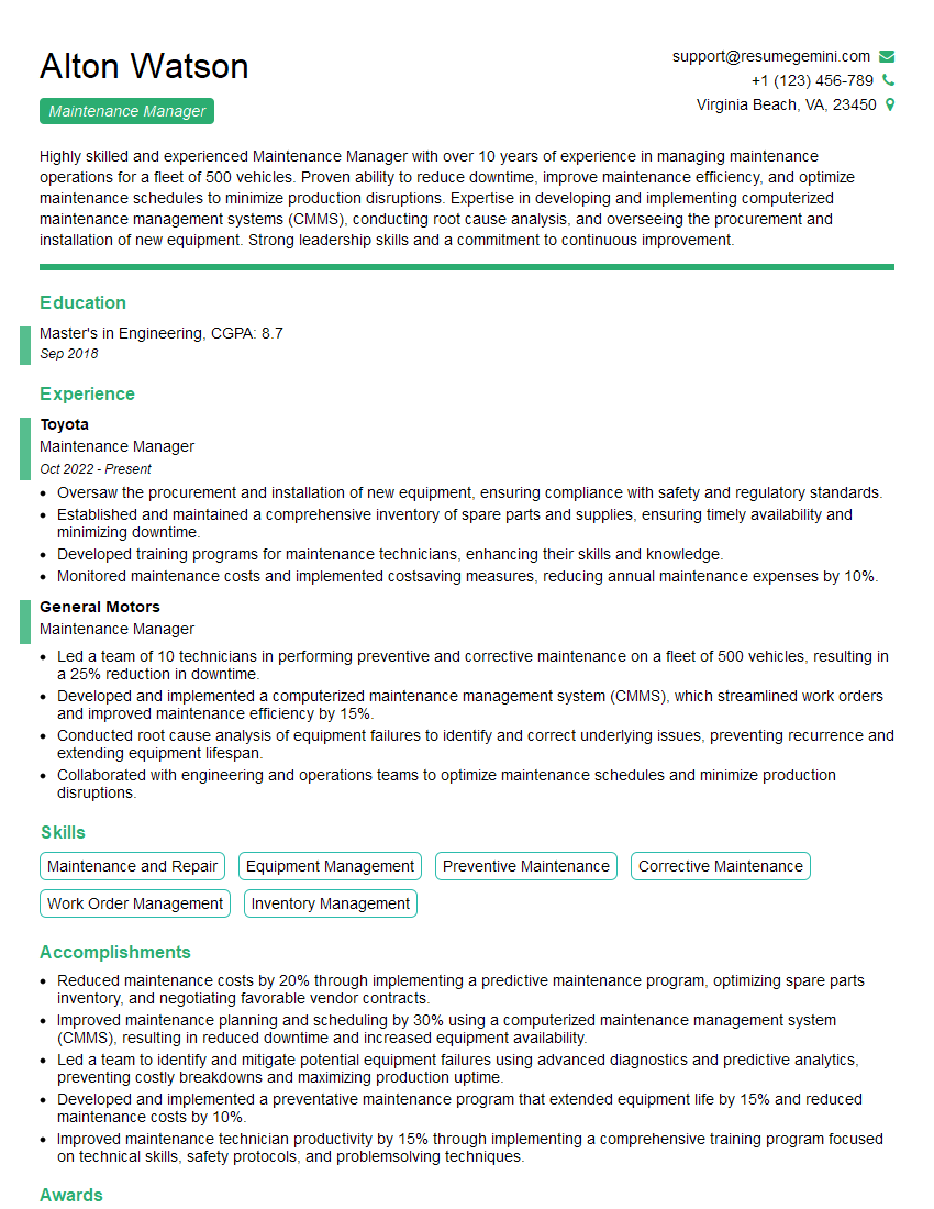
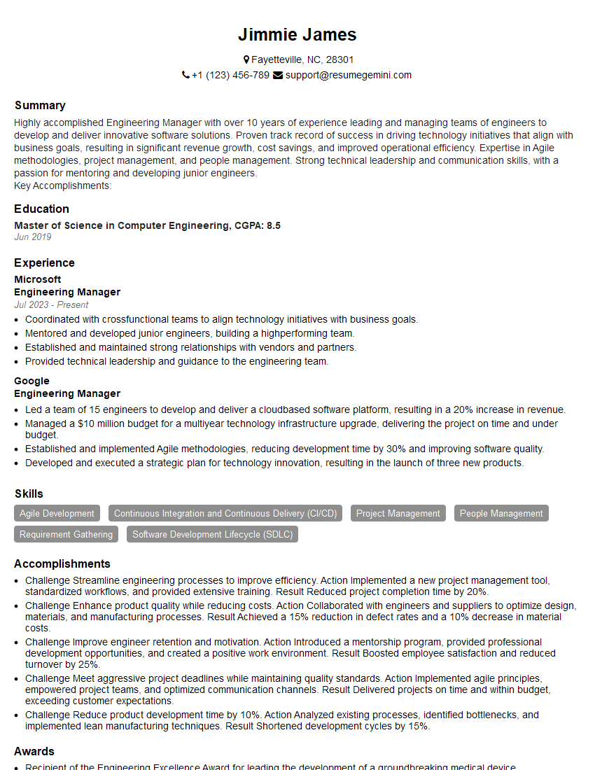
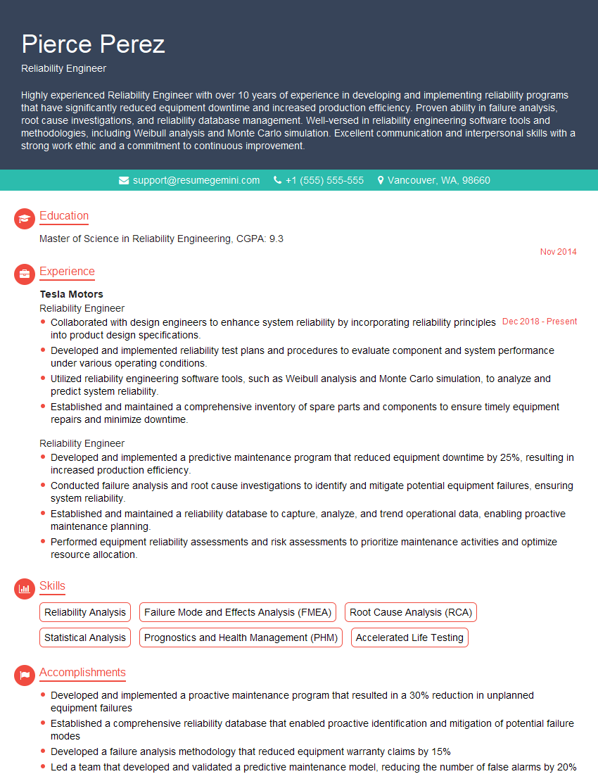
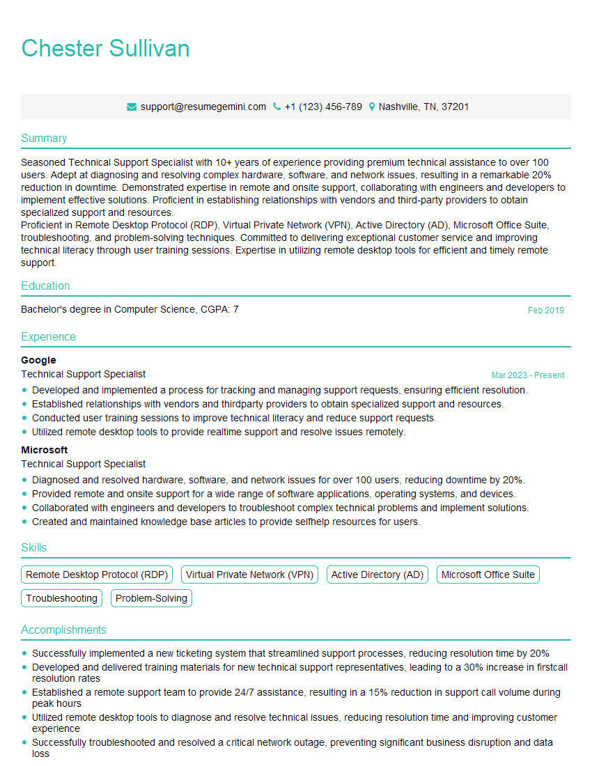
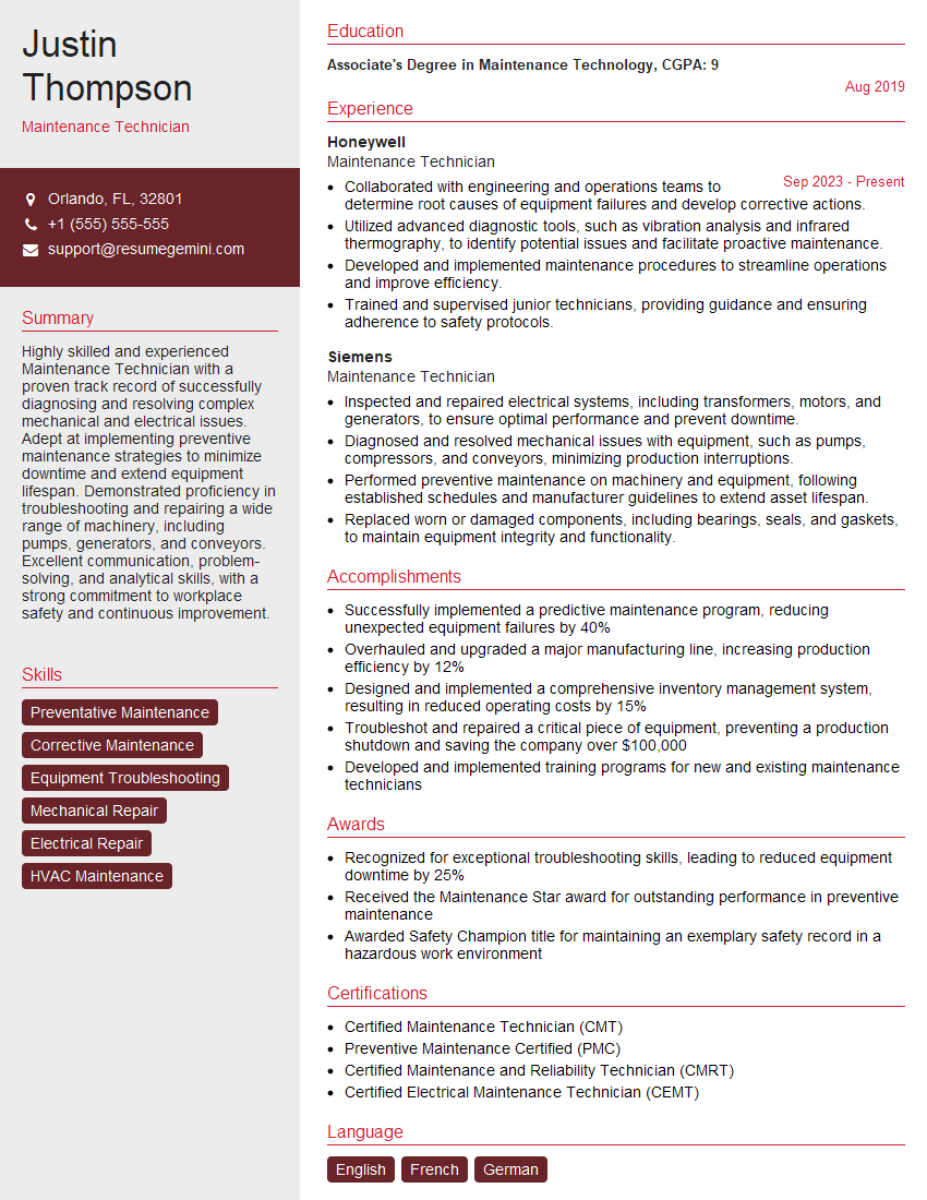
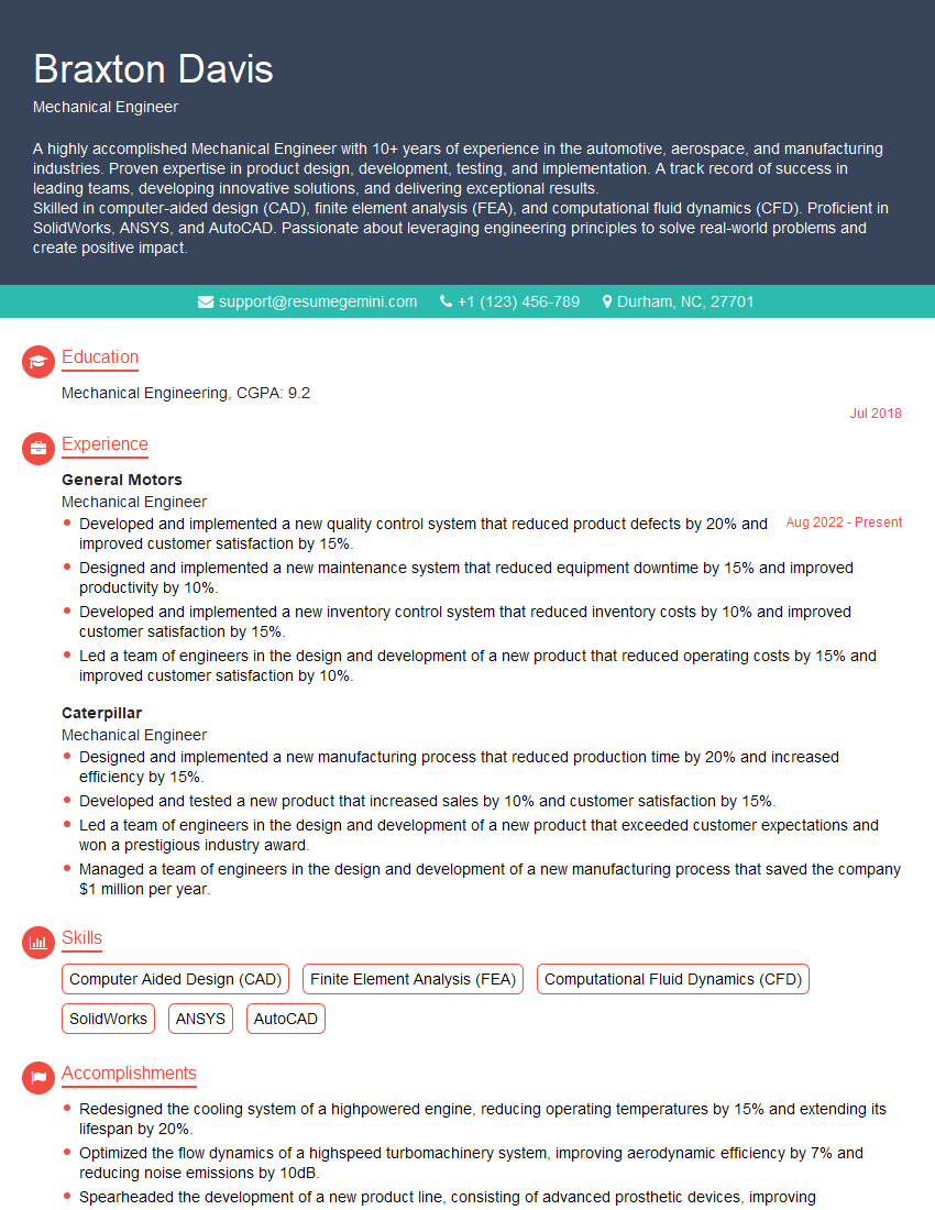
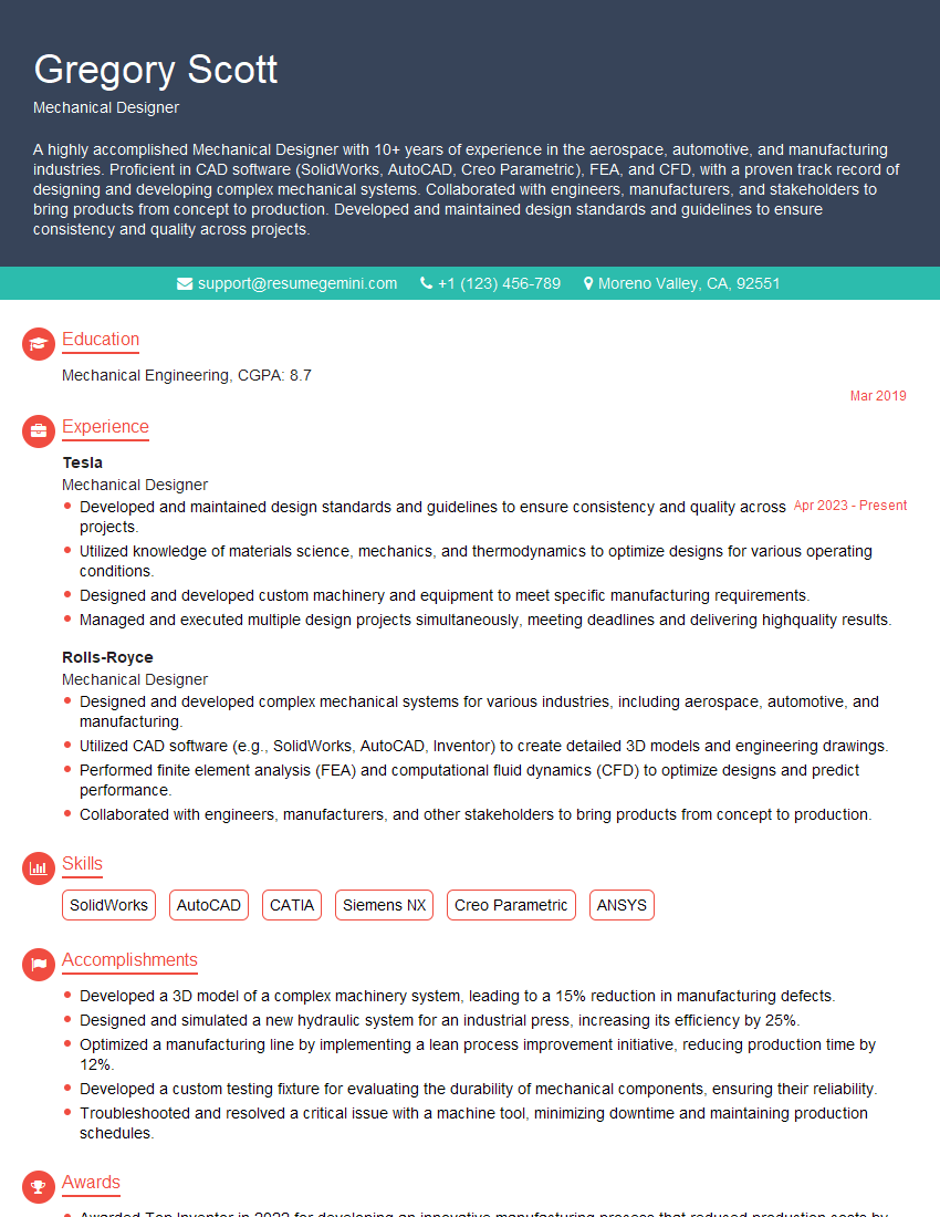
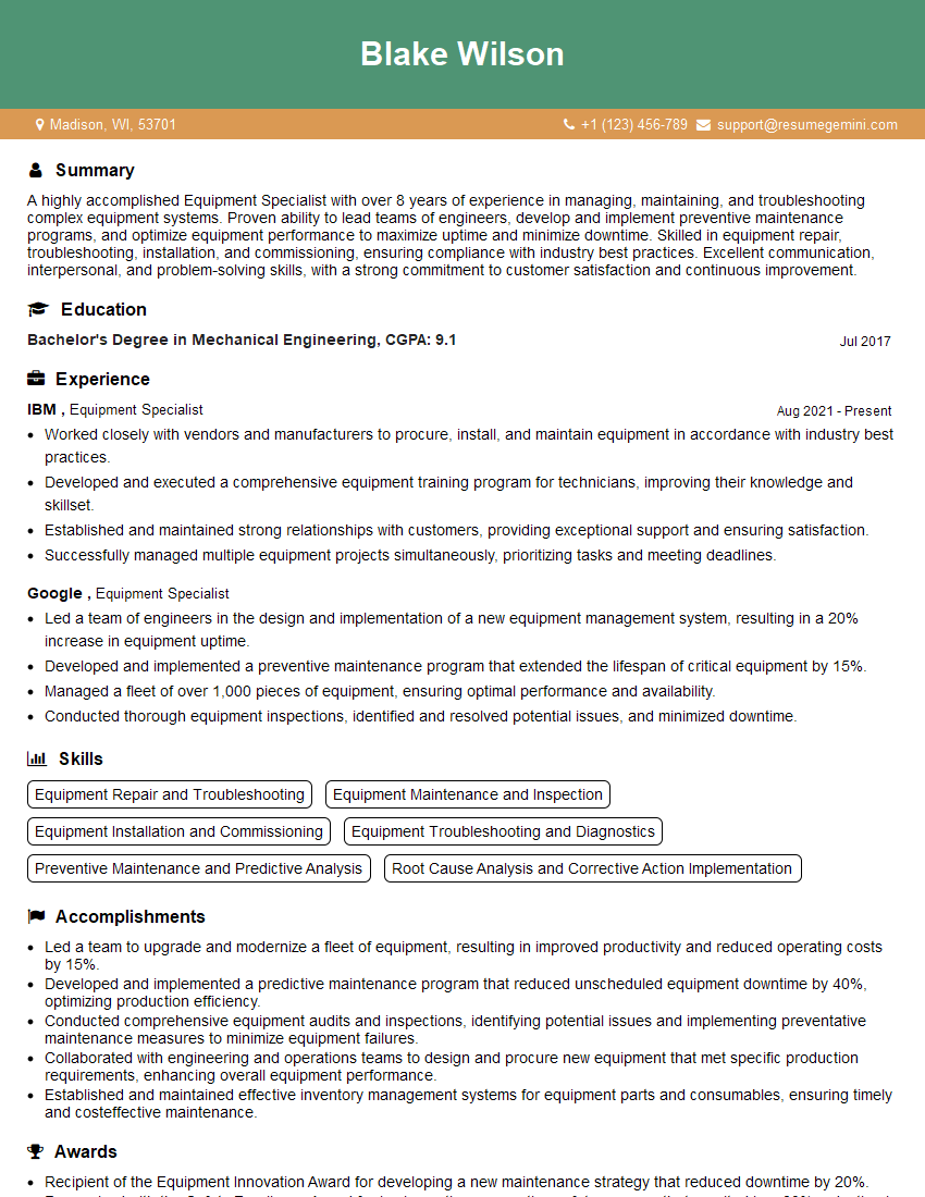
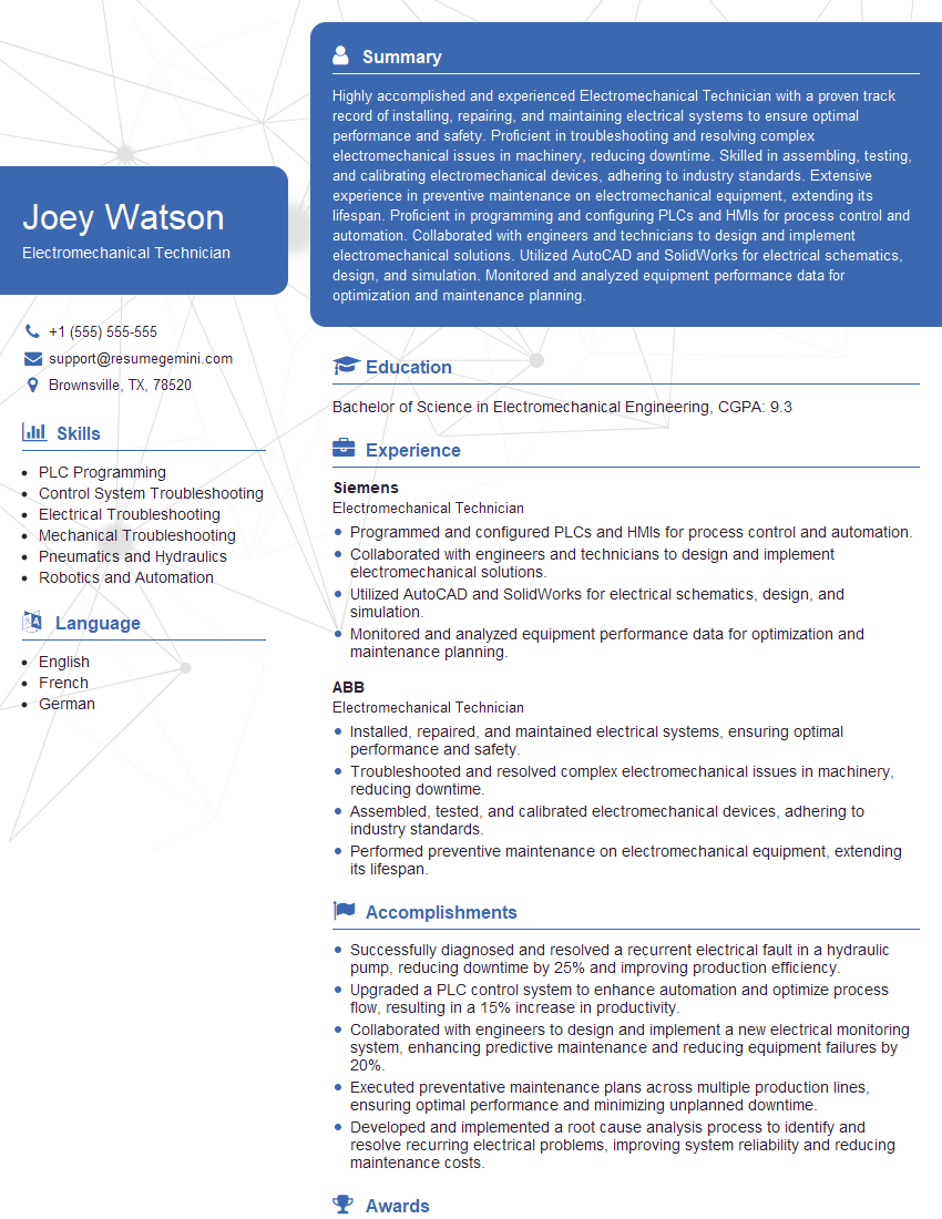
Mastering the intricacies of Electrical and Mechanical Equipment is crucial for career advancement in numerous high-demand industries. A strong understanding of these principles opens doors to exciting roles and significant professional growth. To maximize your job prospects, create an ATS-friendly resume that showcases your skills and experience effectively. ResumeGemini is a trusted resource to help you build a professional and impactful resume that gets noticed. We provide examples of resumes tailored to the Electrical and Mechanical Equipment field to guide you through the process. Let us help you craft a resume that reflects your expertise and secures your dream job.
Explore more articles
Users Rating of Our Blogs
Share Your Experience
We value your feedback! Please rate our content and share your thoughts (optional).
What Readers Say About Our Blog
This was kind of a unique content I found around the specialized skills. Very helpful questions and good detailed answers.
Very Helpful blog, thank you Interviewgemini team.
