The thought of an interview can be nerve-wracking, but the right preparation can make all the difference. Explore this comprehensive guide to Valve Operation and Control interview questions and gain the confidence you need to showcase your abilities and secure the role.
Questions Asked in Valve Operation and Control Interview
Q 1. Explain the difference between globe, ball, and butterfly valves.
Globe, ball, and butterfly valves are all used to control the flow of fluids, but they differ significantly in their design and operation. Think of them as three different tools for the same job, each with its own strengths and weaknesses.
- Globe Valves: These valves use a disc-shaped element that moves up and down to regulate flow. Imagine a plug fitting into a bottleneck. They’re excellent for precise flow control, especially at lower flow rates, and are well-suited for throttling applications, where you need to finely adjust the flow. However, they are less efficient than other valve types at higher flow rates because of the flow restriction.
- Ball Valves: These employ a rotating spherical ball with a hole through its center. Picture a ball bearing with a hole that can be aligned or misaligned with the flow. When the hole is aligned, the flow is open; when it’s turned, flow is stopped. Ball valves are known for their quick on/off operation and low pressure drop when fully open. They aren’t as suitable for precise throttling because their flow regulation isn’t as gradual.
- Butterfly Valves: These valves use a circular disc that rotates to control flow. Think of a door swinging to partially or fully obstruct a pipe. They offer simple operation, compact design, and are often preferred for large diameter pipelines, where their lighter weight and simpler mechanism are advantageous. They are usually not as accurate for throttling as globe valves, but offer more reliable, larger-scale on/off control compared to ball valves.
The best choice depends on the specific application requirements. For instance, a globe valve might be ideal for regulating the flow of a chemical process, while a butterfly valve would be a better fit for a large water supply line.
Q 2. Describe the operation of a pneumatic actuator.
A pneumatic actuator is like a powerful muscle for your valve. It uses compressed air to convert pneumatic energy into mechanical movement, opening or closing the valve. Here’s how it works:
1. Compressed Air Supply: The actuator receives compressed air from a regulated source.
2. Control Signal: A control signal, usually from a Programmable Logic Controller (PLC) or other automation system, determines the valve’s position.
3. Air Flow Control: Based on the control signal, the actuator directs compressed air to either the opening or closing side of a diaphragm or piston inside the actuator.
4. Mechanical Movement: The pressure difference between the two sides of the diaphragm or piston creates a force that moves a stem connected to the valve, either opening or closing it.
5. Feedback Mechanism (Optional): Many pneumatic actuators include a feedback mechanism, such as a positioner, to ensure accurate positioning and prevent over-travel.
Example: Imagine a large water valve in a water treatment plant. A pneumatic actuator, powered by compressed air, is used to open or close the valve based on the water demand, as controlled by a PLC. The PLC monitors water levels and sends the appropriate signal to the actuator, ensuring the consistent delivery of treated water.
Q 3. How do you troubleshoot a leaking valve?
Troubleshooting a leaking valve requires a systematic approach. Remember safety first; always isolate the valve before any investigation.
- Identify the Leak Source: Pinpoint the exact location of the leak. Is it at the stem, body, or packing gland?
- Check Packing Gland: If the leak is around the stem, the packing gland might be worn or damaged. Tightening the gland nut can often fix minor leaks, but excessive tightening can damage the stem.
- Inspect the Valve Body: Look for cracks, corrosion, or damage to the valve body itself. This often requires replacing the entire valve.
- Examine the Valve Seat: A damaged or worn valve seat can cause a leak. Depending on the valve type, the seat might need repair, replacement or specialized machining.
- Check Valve Alignment: Verify the valve is properly aligned in the pipeline. Misalignment can cause undue stress, leading to leaks.
- Test for Pressure: Ensure the system pressure is within the valve’s operating limits. Excessive pressure can damage seals and cause leaks.
Example: In an oil refinery, a leaking globe valve on a high-pressure line presents a safety and environmental hazard. By following this procedure, the maintenance crew can systematically diagnose the problem, determining whether a simple packing gland tightening is sufficient, or if a more extensive valve overhaul or replacement is needed.
Q 4. What are the common causes of valve failure?
Valve failures can stem from various causes. Here are some of the most common:
- Corrosion: Chemical reactions degrade the valve materials, weakening them and causing leaks or malfunctions. This is especially prevalent in harsh environments.
- Erosion: The constant flow of fluids, particularly abrasive ones, can wear down valve components, especially the seat and disc.
- Cavitation: The formation and collapse of vapor bubbles in a fluid under pressure can erode valve surfaces and cause damage.
- Improper Operation: Frequent cycling, over-tightening, or operation outside the valve’s pressure and temperature limits can lead to premature wear and failure.
- Lack of Maintenance: Neglecting regular inspection and maintenance, such as lubrication and packing gland adjustment, accelerates valve degradation.
- Failure of Actuators or Positioners: Problems with the control mechanisms can prevent the valve from functioning correctly.
Example: A butterfly valve in a wastewater treatment plant fails due to corrosion from the highly corrosive nature of the wastewater. This demonstrates the importance of selecting corrosion-resistant materials for valves in aggressive environments.
Q 5. Explain the concept of valve sizing.
Valve sizing is critical for ensuring a valve can handle the required flow rate and pressure drop without compromising performance or longevity. It’s about finding the right size valve for the job – too small, and you’ll have excessive pressure drop; too large, and you might lose control.
Valve sizing involves calculating the required valve diameter (or flow area) based on factors like:
- Flow rate: The volume of fluid to be passed through the valve per unit time.
- Fluid properties: Viscosity, density, and temperature of the fluid.
- Pressure drop: The acceptable pressure loss across the valve.
- Valve type: Different valve types have different flow characteristics.
Specialized software and calculation methods are employed, often considering pressure drop charts and flow coefficient (Cv) values specific to the valve type and manufacturer.
Example: Designing a water distribution system requires sizing several valves to ensure adequate water flow to different areas while minimizing pressure drops. A smaller valve in a smaller branch line will likely have a lower Cv than a larger valve on the main line. Improper sizing could lead to low water pressure in certain areas.
Q 6. How do you perform a valve inspection?
Regular valve inspection is essential for preventing failures and ensuring safe and efficient operation. The specifics depend on the valve type, application, and local regulations, but a typical inspection includes:
- Visual Inspection: Check for visible damage, corrosion, leaks, or signs of wear on the valve body, stem, packing gland, and actuator.
- Functional Test: Manually operate the valve (if safe to do so) through its full range of motion, checking for smooth operation and proper seating.
- Leakage Test: Check for leaks around the stem, body, or seat. This might involve applying pressure and observing for any leaks.
- Actuator/Positioner Check: Inspect and test the actuator or positioner for proper functionality and accuracy.
- Documentation: Record the findings of the inspection, including any needed repairs or maintenance.
Example: A regular inspection of safety relief valves in a chemical plant reveals a slight leak in one of the valves. Early detection prevents a potentially dangerous failure and allows for timely repair.
Q 7. What are different types of valve positioners and their applications?
Valve positioners enhance the accuracy and responsiveness of pneumatic actuators. They act as a “smart muscle” providing feedback and fine-tuning.
- Electro-pneumatic Positioners: These positioners use an electrical signal from a control system to precisely adjust the air pressure to the actuator, achieving accurate positioning. They’re ideal for applications demanding precise control, such as those found in process automation.
- Pneumatic Positioners (I/P Converters): These convert a pneumatic input signal (e.g., from a PLC) into the correct air pressure for the actuator. While not as precise as electro-pneumatic positioners, they are a robust and reliable solution for more straightforward applications.
- Smart Positioners: These advanced positioners incorporate features like diagnostics, feedback mechanisms, and communication capabilities. They provide real-time information on the valve’s status, allowing for predictive maintenance and improved process control. They’re often found in complex, critical applications requiring advanced monitoring and control.
Example: In a power plant, a smart positioner on a large control valve provides real-time feedback, improving the accuracy of steam flow control and enhancing overall plant efficiency. Early detection of potential problems via the smart positioner’s diagnostics allows for proactive maintenance.
Q 8. Describe the function of a valve limit switch.
A valve limit switch is a safety device that indicates the position of a valve – whether it’s fully open, fully closed, or somewhere in between. Think of it as a simple on/off sensor for the valve’s position. It’s crucial for automation and safety systems. The switch activates when the valve reaches a certain point in its travel, sending a signal to a control system. This signal can then be used to trigger other actions or provide feedback to the control system about the valve’s status.
For example, in a process where a valve needs to be fully open before a pump can start, a limit switch ensures the pump doesn’t activate until the valve is fully open, preventing damage to the pump or system. Another example would be a safety shutdown; if a valve fails to close completely, a limit switch will signal an emergency shutdown preventing a potential hazard.
Q 9. Explain the principles of proportional, integral, and derivative (PID) control.
PID control is a widely used feedback control loop mechanism used to maintain a desired process variable, such as temperature or pressure, at a setpoint. It uses three parameters: Proportional (P), Integral (I), and Derivative (D) to adjust the valve’s position to achieve this.
Proportional (P): This term responds to the error, which is the difference between the setpoint and the current process variable. A larger error results in a larger valve adjustment. Think of it as a direct relationship; the further you are from the target, the harder you correct. However, P control alone often leads to a steady-state error, meaning the process variable will never quite reach the setpoint.
Integral (I): This component addresses the steady-state error. It accumulates the error over time. The longer the error persists, the stronger the corrective action. Imagine it as remembering past mistakes and working to correct them. This eliminates the steady-state error but can lead to overshoot and oscillations if not tuned properly.
Derivative (D): This term anticipates future changes based on the rate of change of the error. It reduces overshoot and oscillations by slowing down the valve adjustment as the setpoint is approached. Think of it as a prediction mechanism, preventing drastic actions when the system is close to the target.
In essence, PID control combines these three actions to provide smooth, accurate control. The relative contribution of each term (P, I, and D) is determined by tuning the controller to match the specific process characteristics.
Q 10. How do you calibrate a valve?
Calibrating a valve involves verifying and adjusting its operation to ensure it accurately controls the flow of the process fluid within its designed specifications. The process varies slightly depending on the valve type and actuator, but generally involves these steps:
Verification of Valve Position: Using a suitable measuring instrument (e.g., a dial indicator or a digital positioner), determine the actual valve position (open/close percentage) at different points in its stroke. This can involve opening the valve fully and comparing the reading to the full-open indication (and repeating this for the closed position).
Actuator Calibration (if applicable): Actuators (e.g., pneumatic, electric) need calibration to ensure correct valve stem movement corresponding to the control signal. This often involves adjusting the actuator’s travel limits to match the valve’s physical limits.
Flow Measurement: For valves controlling flow rate, you need to measure the actual flow through the valve at different positions. Compare these readings to the expected flow for each valve position. Flow meters or differential pressure gauges can be used for this.
Adjustment and Re-Verification: If discrepancies exist between the actual and expected values, adjustments may be required, such as adjusting the actuator’s limit switches or making mechanical adjustments to the valve itself. Repeat the verification process after any adjustments.
Documentation: Once the calibration is complete, the results should be documented for traceability and record-keeping purposes.
Calibration is critical for ensuring accurate process control and avoiding costly production issues.
Q 11. What safety precautions should be taken when working with valves?
Safety precautions when working with valves are paramount. Failure to adhere to them can result in serious injury or even death. Here are some key considerations:
Lockout/Tagout (LOTO): Always use LOTO procedures before performing any maintenance or repair on valves, especially those in high-pressure systems. This ensures the valve cannot be inadvertently opened or closed during work.
Pressure Relief: Before working on any pressurized valve, ensure the pressure is fully relieved and the system is depressurized. Use appropriate pressure relief valves and verification methods.
Personal Protective Equipment (PPE): Wear appropriate PPE, including safety glasses, gloves, and potentially hearing protection depending on the system. If working with hazardous materials, consider additional PPE like respirators.
Confined Space Entry: If working in confined spaces around valves, follow all confined space entry procedures, including atmospheric testing and proper ventilation.
Elevated Work: If working at heights, utilize proper fall protection measures.
Awareness of Surroundings: Be aware of the surroundings and potential hazards in the area, such as moving equipment or hot surfaces.
Safety should always be the top priority when working with valves.
Q 12. Explain the concept of valve packing and its importance.
Valve packing is a material, usually a type of flexible sealing element (like graphite, PTFE, or braided materials), that is compressed around the valve stem to create a seal. This seal prevents leakage of the process fluid around the stem as the valve opens and closes. Think of it as a gasket around the moving part of the valve, preventing leaks.
Its importance is crucial for several reasons:
Leak Prevention: This is its primary function. Leaks can lead to loss of valuable product, environmental damage, safety hazards, and equipment damage.
Process Integrity: Preventing leaks maintains the integrity of the process, ensuring that the controlled fluid remains contained and that the process operates as designed.
Environmental Protection: Leak prevention is vital in protecting the environment from harmful emissions or spills.
Safety: Leaks can create hazardous conditions, such as toxic or flammable gas releases. Proper packing helps avoid these risks.
Regular inspection and replacement of valve packing are vital for maintaining system integrity and safety.
Q 13. Describe different types of valve actuators (e.g., electric, hydraulic, pneumatic).
Valve actuators are mechanisms that provide the force required to move the valve stem and control the flow. Different types of actuators exist, each with its own advantages and disadvantages:
Electric Actuators: These use electric motors to provide the force. They are often used in applications requiring precise control and automation, often controlled by a programmable logic controller (PLC). They are relatively clean and quiet, but can be more sensitive to power outages.
Hydraulic Actuators: These utilize hydraulic fluid under pressure to generate the force. They are extremely powerful and suitable for large valves or high-pressure applications. They offer quick response times, but are less precise than electric actuators and require a hydraulic power supply.
Pneumatic Actuators: These use compressed air to generate the force. They are generally less expensive and simpler to maintain than hydraulic actuators, and are well-suited for applications where compressed air is readily available. They are also reliable in hazardous environments, but may be less accurate than electric actuators.
The choice of actuator depends on factors such as the valve size, required force, control precision, available power source, and the operating environment.
Q 14. What is the purpose of a valve stem?
The valve stem is the part of a valve that moves to control the opening and closing of the valve. It’s the central, moving component that is connected to the valve actuator. Think of it as the shaft that directly controls whether the valve is open or closed.
Its purpose is to transmit the force from the actuator to the valve disc or plug, precisely controlling the flow rate. It also provides a surface for sealing elements (like the packing) to prevent leaks.
Q 15. How do you identify a damaged valve?
Identifying a damaged valve involves a multi-pronged approach combining visual inspection with functional testing. First, visually inspect the valve for obvious signs of damage: leaks around the stem or body, cracks in the valve body or bonnet, significant corrosion, or damage to the actuator (the mechanism that opens and closes the valve). Look for signs of wear and tear on the packing gland (the area sealing the stem). Next, check for proper operation. If it’s a manually operated valve, try opening and closing it; does it move freely? Is there unusual resistance or sticking? For automated valves, monitor its response to control signals. Slow response or failure to reach the commanded position indicates a potential problem. Finally, you might need to use specialized tools such as pressure gauges to check for internal leaks or flow imbalances. Remember, safety is paramount! Always isolate the valve from the system before carrying out detailed inspections or repairs.
Example: Imagine a gate valve used in a water pipeline. If you notice water constantly dripping from the stem packing, it indicates damage to the packing, requiring replacement. Similarly, a significantly corroded valve body indicates the need for replacement due to potential structural failure.
Career Expert Tips:
- Ace those interviews! Prepare effectively by reviewing the Top 50 Most Common Interview Questions on ResumeGemini.
- Navigate your job search with confidence! Explore a wide range of Career Tips on ResumeGemini. Learn about common challenges and recommendations to overcome them.
- Craft the perfect resume! Master the Art of Resume Writing with ResumeGemini’s guide. Showcase your unique qualifications and achievements effectively.
- Don’t miss out on holiday savings! Build your dream resume with ResumeGemini’s ATS optimized templates.
Q 16. Explain the difference between a normally open (NO) and normally closed (NC) valve.
Normally Open (NO) and Normally Closed (NC) valves are fundamental concepts. An NO valve is designed to allow flow when there is no actuating signal. Think of it like an open doorway: flow passes through freely unless something actively closes it. Conversely, an NC valve restricts flow when there is no actuating signal – it’s like a closed door; flow is blocked until something opens it. The choice between NO and NC depends entirely on the safety and operational requirements. For instance, an NO valve might be used for emergency shutdown – a failure in the system would result in the valve opening. An NC valve might be preferred where preventing flow in the default state is crucial, such as in a safety interlock system.
Example: In a fire suppression system, a normally closed valve is essential. It remains closed until a fire alarm triggers the opening, releasing the extinguishing agent. In contrast, a gas supply line might use a normally open valve, closing only in the event of a leak or emergency.
Q 17. How do you troubleshoot a valve that is not opening or closing properly?
Troubleshooting a malfunctioning valve requires a systematic approach. First, determine whether the problem is mechanical (sticking, binding) or pneumatic/electrical (inadequate signal, power failure). Start with the simplest checks: ensure power supply is adequate for automated valves, and check if the actuator is receiving the correct control signal. For manually operated valves, try to operate it by hand; binding could be due to corrosion, debris, or simply lack of lubrication. If it’s an automated valve, check the control system for errors; faulty sensors or controllers can cause malfunction. If the problem persists, inspect the valve internals. This often necessitates isolating the valve from the system for safety, and careful dismantling to identify the cause – seized internal parts, damaged seals, or foreign material obstructing flow are all possibilities. Remember to consult the manufacturer’s documentation for specific troubleshooting procedures.
Example: A pneumatic valve failing to open could be due to a lack of air pressure or a leak in the actuator’s air supply line. A stuck manual valve could be remedied by lubricating its moving parts.
Q 18. What are the different types of valve materials and their applications?
Valve materials are selected based on the fluid being handled, the operating temperature and pressure, and the corrosive nature of the environment. Common materials include:
- Carbon Steel: Cost-effective, widely used for water, steam, and oil, but susceptible to corrosion. Used in less demanding applications.
- Stainless Steel: Excellent corrosion resistance, ideal for aggressive chemicals, high temperatures, and high pressures. More expensive than carbon steel.
- Cast Iron: Durable and cost-effective for low-pressure applications, but more brittle than steel.
- Brass: Good corrosion resistance, often used in low-pressure applications with water or less corrosive gases.
- PVC/CPVC: Used for corrosive fluids and in chemical processing, but with limitations in temperature and pressure.
- Plastic (various types): Used in applications requiring chemical resistance and low cost but usually at lower pressures and temperatures.
The selection depends heavily on the application. A valve handling highly corrosive acids would require stainless steel or a specialized alloy, whereas a valve in a low-pressure water system might be made of carbon steel or brass.
Q 19. Explain the concept of valve trim.
Valve trim refers to the internal components of a valve that directly affect the flow characteristics. This includes the seat, disc (or plug), and other components involved in regulating the flow. The trim material and design significantly impact the valve’s performance parameters such as flow coefficient (Cv), pressure drop, cavitation resistance, and wear resistance. Proper trim selection is critical for optimizing the valve’s performance within a specific application, ensuring that it meets the required flow control and longevity. A valve with an improperly selected trim can lead to premature wear, excessive noise or vibration, and poor control of the process fluid.
Example: A valve handling abrasive slurry might use a hardened trim material to prevent premature wear and tear. A valve operating under high pressure might require a trim design that minimizes cavitation.
Q 20. Describe the importance of regular valve maintenance.
Regular valve maintenance is crucial for ensuring safe and efficient operation, preventing costly downtime, and extending the valve’s lifespan. A preventative maintenance program should include:
- Visual inspection: Regularly check for leaks, corrosion, damage, and proper operation.
- Lubrication: Regular lubrication of moving parts is essential to reduce friction and wear.
- Actuator testing: For automated valves, test the actuator’s functionality and response.
- Packing gland adjustment: Adjust the packing gland to prevent leaks around the valve stem.
- Internal inspection and cleaning: Periodically disassemble the valve for cleaning, inspection, and replacement of worn parts.
The frequency of maintenance depends on the valve’s usage, the operating conditions, and the fluid being handled. A valve in a critical application might require more frequent maintenance than one in a less demanding setting. Neglecting maintenance can lead to unexpected failures, resulting in process upsets, safety hazards, and increased repair costs.
Q 21. How do you select the appropriate valve for a specific application?
Selecting the right valve for a specific application requires a thorough understanding of the process parameters and operational requirements. Consider the following factors:
- Fluid properties: Viscosity, temperature, pressure, corrosiveness, and abrasiveness of the fluid.
- Flow characteristics: Required flow rate, pressure drop, and flow control accuracy.
- Operating conditions: Temperature, pressure, and environmental factors.
- Valve type: Different valve types (ball, gate, globe, butterfly, etc.) have distinct characteristics suited for different applications.
- Material compatibility: Valve materials must be compatible with the fluid being handled.
- Actuator requirements: Manual or automated operation, type of actuator (pneumatic, electric, hydraulic).
- Safety and regulatory considerations: Compliance with relevant industry standards and safety regulations.
By carefully evaluating these factors, you can choose the optimal valve that ensures safe, efficient, and reliable operation. Often, consulting valve manufacturer catalogs and utilizing selection software aids the process. A poorly selected valve can result in operational inefficiencies and potentially hazardous situations.
Q 22. What is the role of a control valve in a process control system?
In a process control system, a control valve acts as the final control element. Think of it as the muscle that carries out the instructions from the brain (the controller). It precisely regulates the flow of fluids (liquids or gases) or slurries within a process by opening or closing in response to a control signal. This ensures the process variable (like temperature, pressure, or flow rate) stays at the desired setpoint. For instance, in a chemical reactor, a control valve might regulate the flow of reactant to maintain a specific reaction temperature. Without precise valve control, the process might become unstable, inefficient, or even dangerous.
Q 23. Explain the concept of valve cavitation and how to prevent it.
Valve cavitation occurs when the pressure within the valve drops below the vapor pressure of the fluid being controlled. This causes the fluid to vaporize, forming bubbles (cavities). When these bubbles collapse, they create shockwaves that can damage the valve’s internal components, leading to noise, vibration, erosion, and ultimately, valve failure. Imagine shaking a soda bottle vigorously – the sudden release of pressure creates bubbles. Cavitation is similar, but with potentially destructive consequences.
Preventing cavitation involves several strategies:
- Increase the downstream pressure: This is often the most effective method. A properly sized pipe and suitable pressure control further downstream can significantly reduce the risk.
- Reduce the valve’s pressure drop: Use a larger valve size to reduce the velocity of the fluid flow, thereby minimizing pressure reduction across the valve.
- Select a suitable valve type: Certain valve designs are less prone to cavitation than others. For instance, control valves with a more streamlined flow path can help mitigate the pressure drop across the valve.
- Avoid using fluids close to their vapor pressure: If possible, operate the process at conditions that ensure a significant margin between the operating pressure and the vapor pressure of the fluid.
Q 24. Describe different types of valve diagnostics and testing methods.
Valve diagnostics and testing methods are crucial for ensuring reliable operation and preventing unexpected failures. Methods range from simple visual inspections to sophisticated automated systems. These include:
- Visual inspection: Checking for leaks, damage, corrosion, and proper alignment.
- Leak testing: Using various methods (e.g., soap solution, pressure testing) to detect leaks in the valve body, stem, or packing.
- Stroke testing: Checking the valve’s full travel and responsiveness by manually or automatically operating it through its entire range of motion. This verifies the correct positioning of the valve and the presence of any mechanical obstruction.
- Performance testing: Measuring the valve’s actual flow characteristics against its design specifications. This may involve measuring flow rate at different valve positions and comparing these with the valve’s inherent CV (flow coefficient) data.
- Acoustic emission testing: Detecting internal valve damage (e.g., cavitation) by monitoring the sound waves generated during operation.
- Smart valve technology: Modern valves often incorporate sensors for diagnostics. These provide real-time data about the valve’s position, flow rate, pressure, and temperature. Analysis of this data can identify potential issues before they lead to failures.
The choice of diagnostic method depends on the valve’s criticality, the process conditions, and available resources. For a critical valve in a safety system, more rigorous testing procedures would be implemented.
Q 25. How do you interpret a valve data sheet?
A valve data sheet is a comprehensive document that provides all the necessary information for selecting, installing, and maintaining a control valve. It contains crucial specifications, including:
- Valve type and size: (e.g., globe valve, ball valve, butterfly valve, and nominal size).
- Materials of construction: (body, trim, seals, etc.) essential for compatibility with the process fluid.
- Pressure ratings: Maximum allowable pressures for various operating conditions.
- Temperature ratings: The range of temperatures the valve can withstand.
- Flow coefficient (Cv): Indicates the valve’s flow capacity. This is critical for proper sizing.
- Actuator specifications: If applicable (e.g., pneumatic, electric, hydraulic). Power requirements, speed, and other parameters are listed.
- Connection types: (e.g., flanged, threaded, welded).
Interpreting this data sheet allows engineers to select the right valve for specific process requirements, ensuring compatibility, safety, and performance. For example, a valve data sheet will inform you about the maximum allowable pressure and temperature for a specific valve, helping you prevent equipment failure.
Q 26. Explain the concept of fail-safe mechanisms for valves.
Fail-safe mechanisms for valves are crucial for safety and process integrity, especially in critical applications. These mechanisms ensure the valve will automatically assume a safe position in case of power failure, instrument malfunction, or other emergencies. The ‘safe’ position is defined based on the process; it could mean fully open, fully closed, or a specific intermediate position, depending on what is safest for the specific application.
Examples include:
- Spring-return actuators: Pneumatic or hydraulic actuators that utilize a spring to return the valve to a predetermined position (usually closed) in case of air or hydraulic pressure loss.
- Fail-open or fail-closed design: The valve’s inherent design (e.g., spring-assisted) determines whether it automatically opens or closes upon failure of the actuator or power supply. Fail-closed is common in safety-critical applications, such as fire protection systems where the valve closing is required for safety.
- Redundant systems: Employing backup systems or multiple actuators to ensure valve functionality even if one component fails.
Properly designed fail-safe mechanisms are essential for preventing accidents and maintaining process stability. The choice of fail-safe mechanism is application-specific, dependent on process hazard analysis and risk assessment. For instance, a gas line will need a fail-closed valve while a process requiring continuous operation might need fail-open protection.
Q 27. What is the difference between a manual and automated valve?
The main difference between manual and automated valves lies in how they are operated:
- Manual valves: Operated manually using a handwheel, lever, or other mechanical means. They are simple and require no external power source. However, manual operation is slow and can be cumbersome in large-scale processes or hazardous environments. Think of a simple gate valve on a garden hose.
- Automated valves: Operated automatically using an actuator (pneumatic, electric, or hydraulic) controlled by a process control system (e.g., PLC or DCS). They offer precise control, speed, and remote operation, significantly improving efficiency and safety. Automated valves are commonly seen in chemical processing plants, power generation facilities and other industrial settings where precise and remote control is required.
The choice between manual and automated valves depends on factors like the process requirements, safety concerns, cost considerations, and the level of control needed. For critical processes where precise control and safety are paramount, automated valves are typically preferred.
Q 28. Describe your experience with different types of valve automation systems (e.g., PLC, DCS).
Throughout my career, I’ve worked extensively with various valve automation systems, including Programmable Logic Controllers (PLCs) and Distributed Control Systems (DCSs).
PLCs are commonly used for simpler applications, often controlling individual valves or smaller groups of valves. I have experience programming PLCs to control the valve position using analog or digital signals from sensors and controllers. For instance, I’ve used PLCs to automate the filling process of a tank by controlling a level sensor and a valve which allows fluid to flow into the tank. The PLC receives the sensor reading, comparing it to the set point, and then sends a signal to the valve actuator to adjust the flow rate accordingly.
DCSs are used for larger, more complex applications, managing multiple loops and hundreds of valves simultaneously. In my experience with DCS, I have participated in designing and implementing advanced control strategies, such as cascade control, feedforward control, and ratio control, for regulating critical process variables. I have successfully utilized the DCS’s functionalities for automated alarming, data acquisition and trending analysis for preventive maintenance and fault detection. This also facilitated better process optimization and improved control performance.
My experience encompasses both the programming and troubleshooting aspects of these systems. I’m proficient in configuring communication protocols (e.g., Modbus, Profibus) for seamless integration between valves, actuators and the higher level control systems.
Key Topics to Learn for Your Valve Operation and Control Interview
- Valve Types and Characteristics: Understand the different types of valves (ball, gate, globe, check, etc.), their operating principles, and their suitability for various applications. Be prepared to discuss their strengths and weaknesses.
- Valve Actuators: Familiarize yourself with various actuator technologies (pneumatic, hydraulic, electric) and their selection criteria based on factors like pressure, flow rate, and response time. Be ready to discuss troubleshooting scenarios.
- Control Systems and Instrumentation: Grasp the fundamentals of process control loops, including sensors, transmitters, controllers, and final control elements. Understand PID control and its tuning parameters.
- Safety and Emergency Shutdown Systems (ESD): Demonstrate knowledge of safety instrumented systems (SIS) and their crucial role in preventing accidents. Discuss the importance of redundancy and fail-safe mechanisms.
- Valve Sizing and Selection: Understand the principles of valve sizing based on flow rate, pressure drop, and other process parameters. Be able to explain the process of selecting the appropriate valve for a given application.
- Troubleshooting and Maintenance: Be prepared to discuss common valve problems, their causes, and effective troubleshooting techniques. Knowledge of preventative maintenance strategies is highly valuable.
- Process Diagrams and Piping & Instrumentation Diagrams (P&IDs): Demonstrate your ability to interpret process flow diagrams and P&IDs, understanding the role of valves within a larger process system.
- Instrumentation and Control Systems (ICS) Security: Understand basic concepts related to securing ICS from cyber threats and vulnerabilities.
Next Steps
Mastering Valve Operation and Control opens doors to exciting and rewarding career opportunities in various industries. A strong understanding of these principles is crucial for advancement and demonstrates a commitment to safety and efficiency. To maximize your job prospects, it’s vital to create a professional and ATS-friendly resume that highlights your skills and experience effectively. ResumeGemini is a trusted resource that can help you build a compelling resume tailored to your specific career goals. We offer examples of resumes tailored to Valve Operation and Control to help you get started. Invest the time to create a powerful resume – it’s your first impression with potential employers.
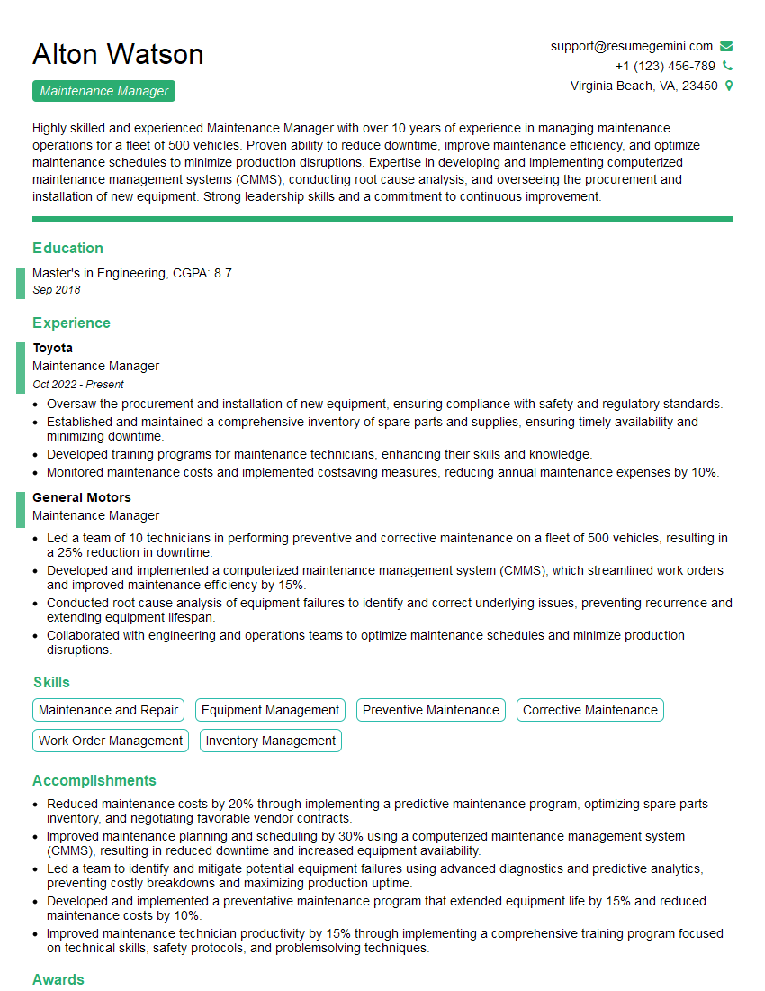
Maintenance Manager Resume Sample
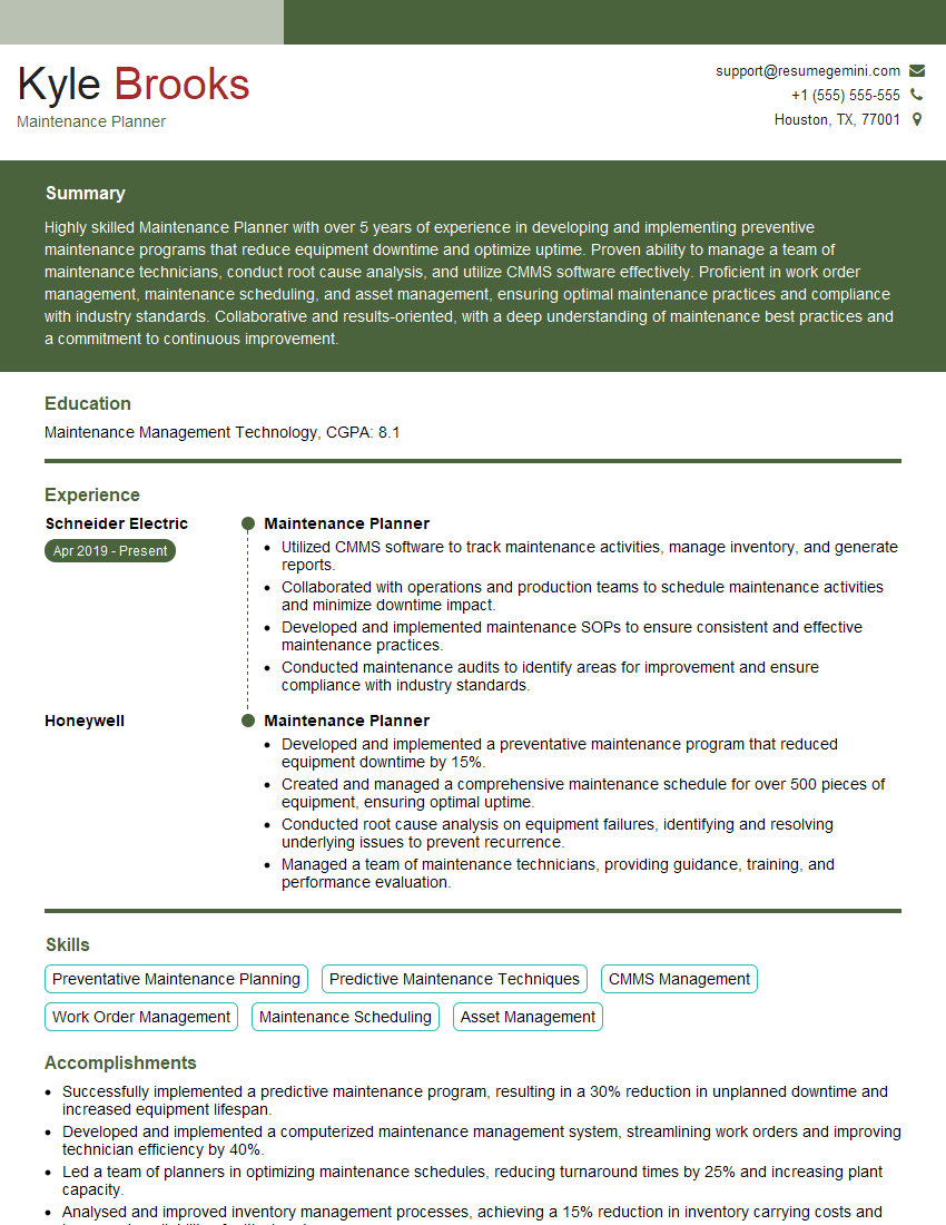
Maintenance Planner Resume Sample
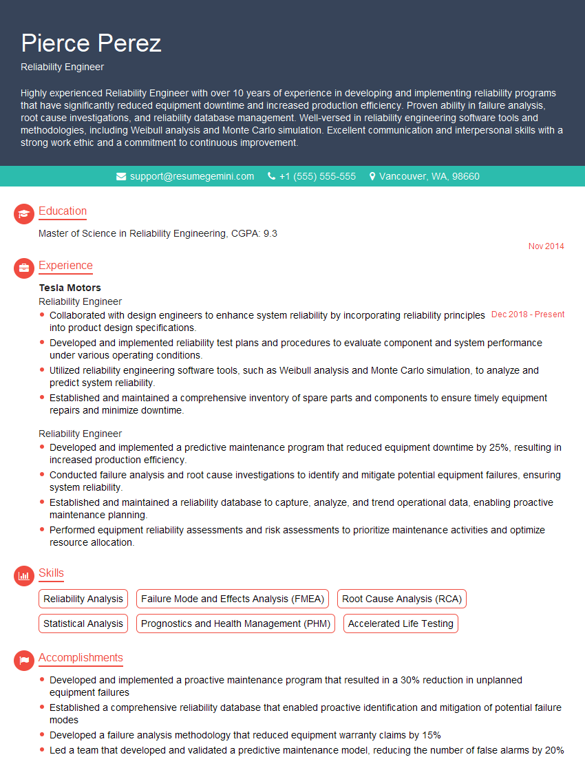
Reliability Engineer Resume Sample
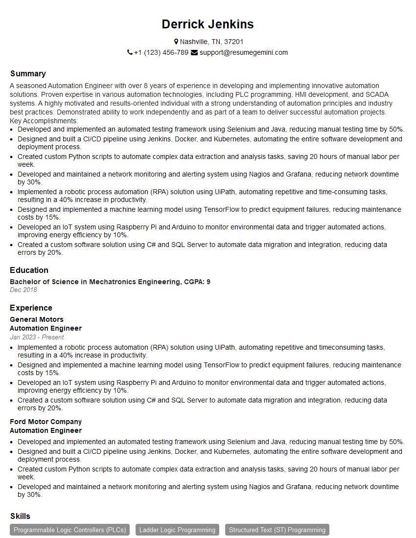
Automation Engineer Resume Sample
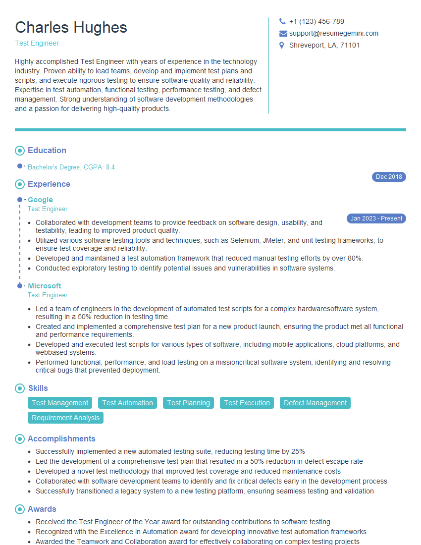
Test Engineer Resume Sample
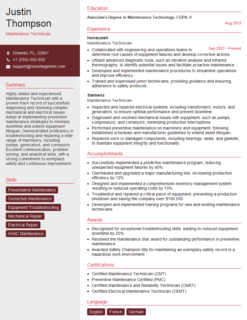
Maintenance Technician Resume Sample
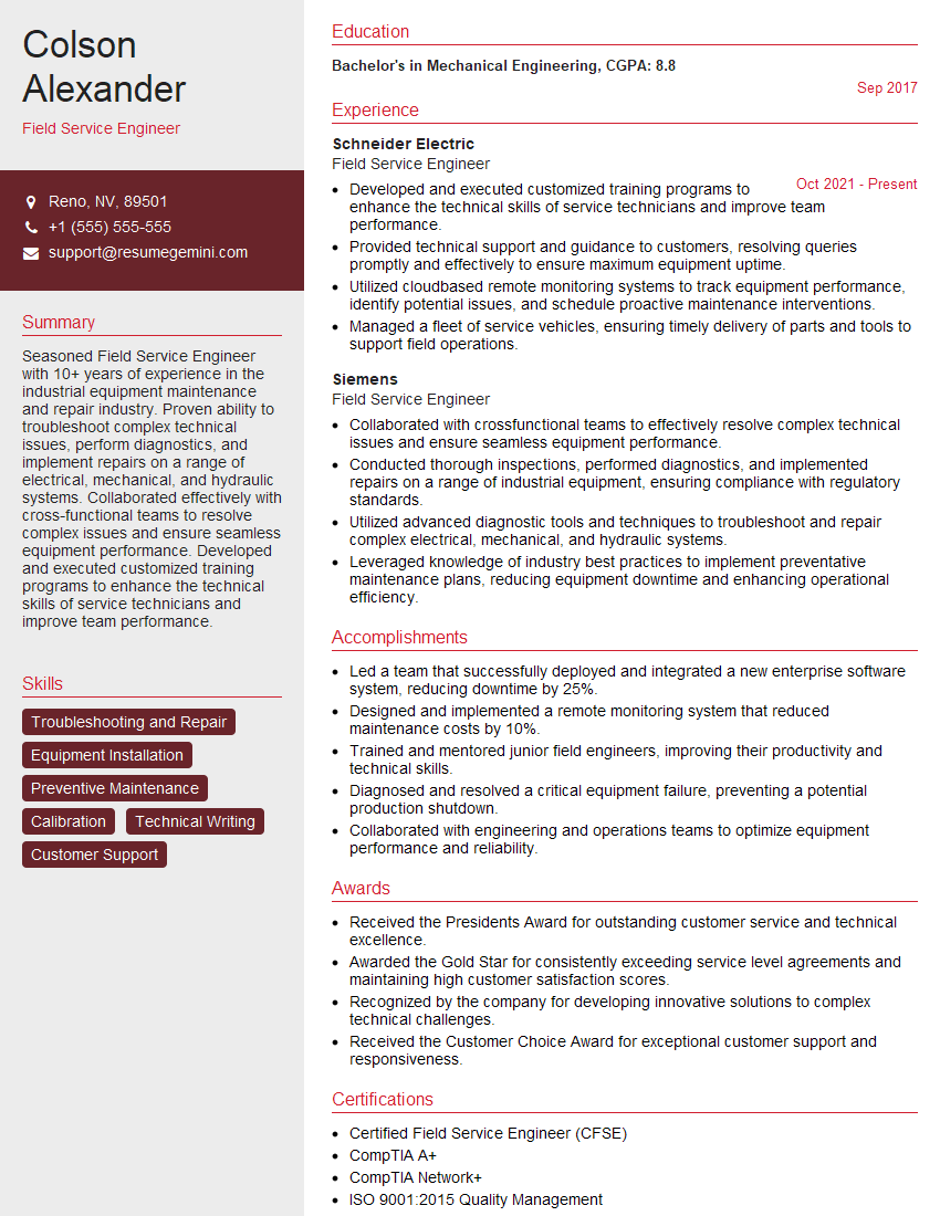
Field Service Engineer Resume Sample

Commissioning Engineer Resume Sample
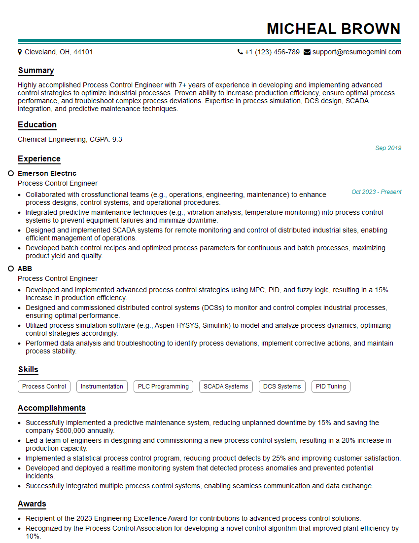
Process Control Engineer Resume Sample

Control Systems Engineer Resume Sample
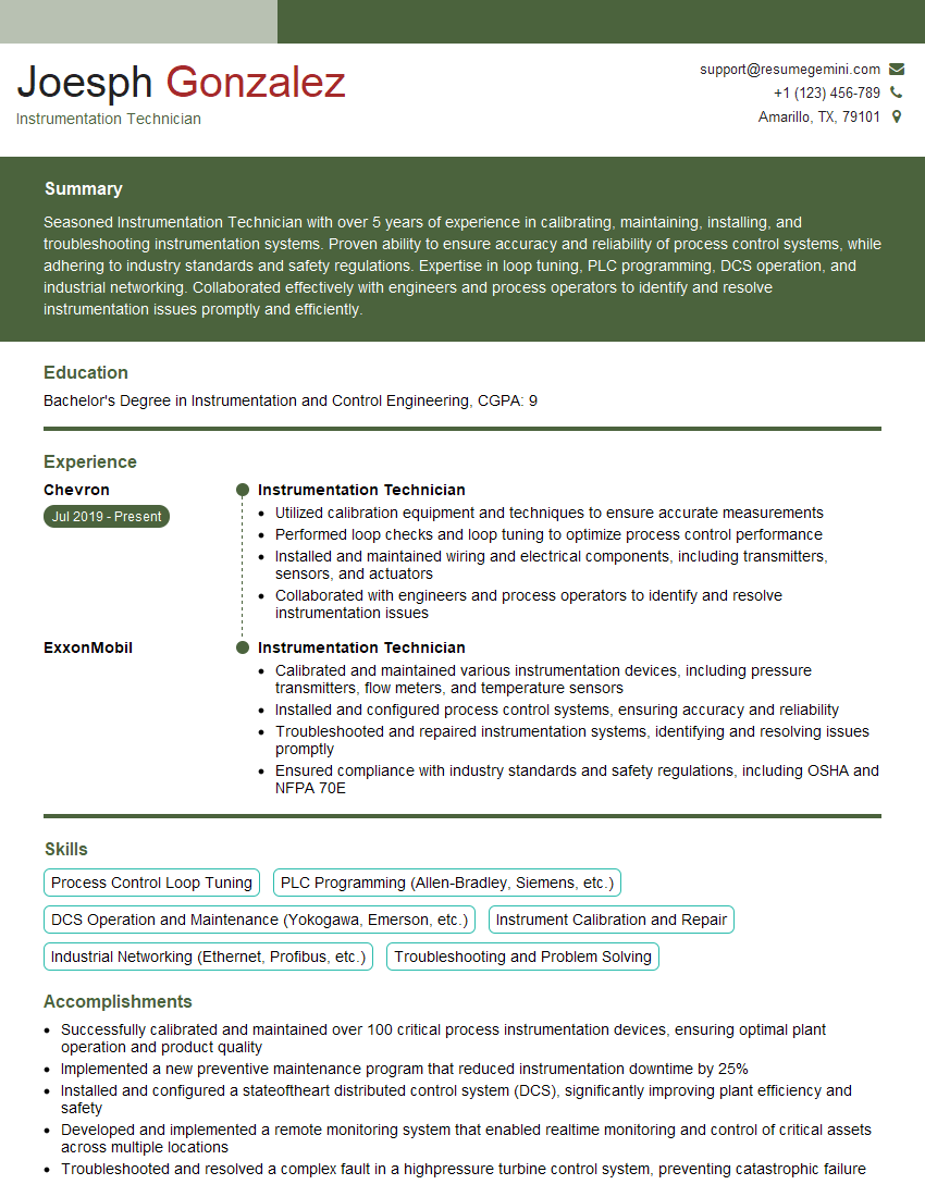
Instrumentation Technician Resume Sample
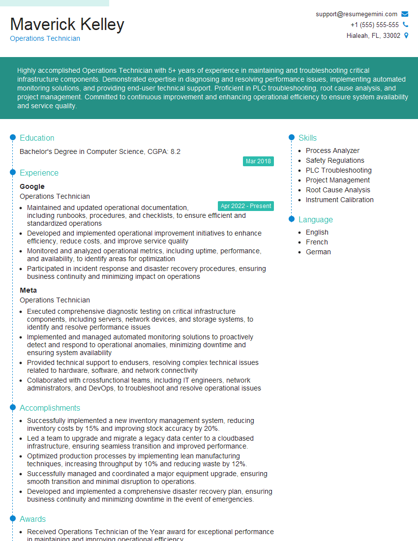
Operations Technician Resume Sample
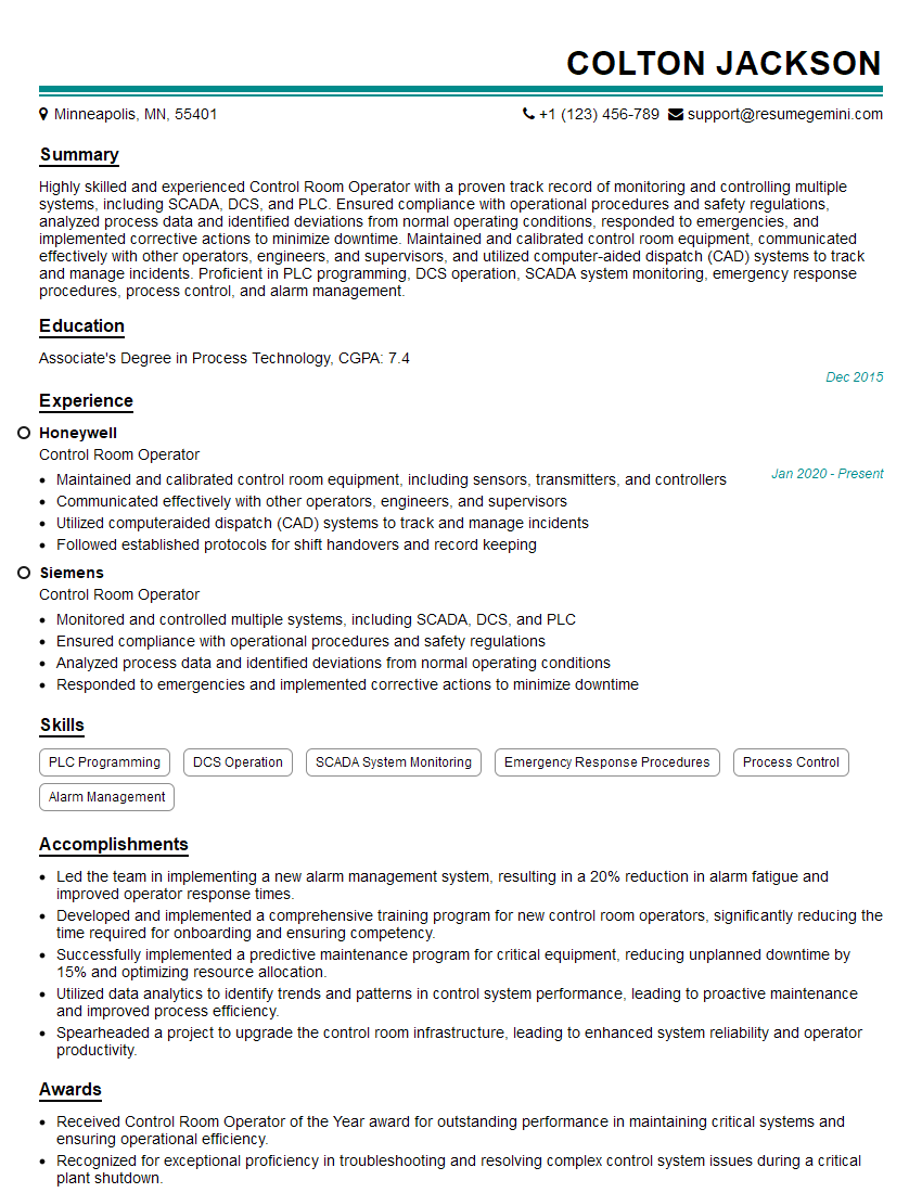
Control Room Operator Resume Sample
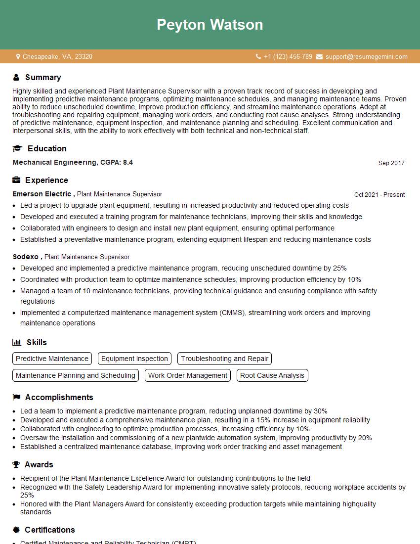
Plant Maintenance Supervisor Resume Sample
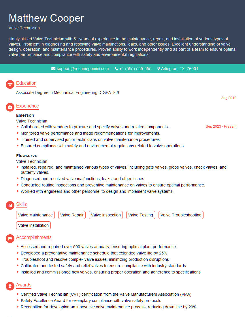
Valve Technician Resume Sample
- Maintenance Manager
- Maintenance Planner
- Reliability Engineer
- Automation Engineer
- Test Engineer
- Maintenance Technician
- Field Service Engineer
- Commissioning Engineer
- Process Control Engineer
- Control Systems Engineer
- Instrumentation Technician
- Operations Technician
- Control Room Operator
- Plant Maintenance Supervisor
- Valve Technician
Explore more articles
Users Rating of Our Blogs
Share Your Experience
We value your feedback! Please rate our content and share your thoughts (optional).
What Readers Say About Our Blog
To the interviewgemini.com Webmaster.
Very helpful and content specific questions to help prepare me for my interview!
Thank you
To the interviewgemini.com Webmaster.
This was kind of a unique content I found around the specialized skills. Very helpful questions and good detailed answers.
Very Helpful blog, thank you Interviewgemini team.