Interviews are opportunities to demonstrate your expertise, and this guide is here to help you shine. Explore the essential Blueprints and Schematic Reading interview questions that employers frequently ask, paired with strategies for crafting responses that set you apart from the competition.
Questions Asked in Blueprints and Schematic Reading Interview
Q 1. Explain the difference between a blueprint and a schematic.
Blueprints and schematics are both technical drawings, but they serve different purposes and have distinct characteristics. Think of a blueprint as a visual representation of a building’s physical structure, showing its layout, dimensions, and construction details. A schematic, on the other hand, focuses on the functional relationships between components within a system, often electrical or electronic. It’s a simplified diagram, showing how things connect and work together, rather than their exact physical placement.
For example, an architectural blueprint will detail the placement of walls, doors, windows, and plumbing fixtures with precise dimensions and materials. An electrical schematic for the same building would show how the electrical circuits are wired, including switches, outlets, and lighting fixtures, without necessarily showing their precise locations within the building. The blueprint shows what is built, while the schematic shows how it functions.
Q 2. Describe the standard symbols used in electrical schematics.
Standard symbols in electrical schematics are standardized to ensure clarity and consistency across projects and companies. They are often governed by industry standards such as IEEE or IEC. Common symbols include:
- Resistors: Represented by a zig-zag line.
- Capacitors: Usually shown as two parallel lines.
- Inductors: Depicted as a coil or spiral.
- Transistors: Have various symbols depending on the type (e.g., NPN, PNP).
- Integrated Circuits (ICs): Represented by a rectangular block with pins.
- Switches: Shown as various switch types, toggle, push button, etc.
- Ground: Often a triangle or a ground symbol.
- Power Sources: Usually a circle with + and – signs.
These symbols allow for a quick understanding of the components and their connections without complex descriptions. A legend is often included on the schematic to clarify any less common or custom symbols.
Q 3. How do you interpret scale on a blueprint?
Blueprint scales indicate the ratio between the drawing’s dimensions and the actual dimensions of the building or object. It’s usually expressed as a ratio (e.g., 1:100, 1/4″ = 1′, etc.). This means that 1 unit on the blueprint represents a certain number of units in reality.
For example, a scale of 1:100 means that 1cm on the blueprint represents 100cm (or 1 meter) in real life. A scale of 1/4″ = 1′ means that 1/4 inch on the blueprint equals 1 foot in the actual construction. Understanding the scale is crucial for accurately measuring distances and sizes from the blueprint. Always check the scale indicated on the blueprint itself, as it can vary from sheet to sheet or project to project.
Q 4. What are the different types of lines used in blueprints and what do they represent?
Blueprints utilize various line types to represent different aspects of the design. These conventions ensure clarity and reduce ambiguity.
- Object Lines: Thick, solid lines define the outlines of walls, fixtures, and other elements.
- Hidden Lines: Dashed lines indicate parts of an object that are not visible from the chosen viewpoint.
- Center Lines: Thin, dashed-dotted lines show the center of symmetrical objects or features.
- Dimension Lines: Thin lines with arrowheads at each end, used to indicate measurements.
- Leader Lines: Thin lines connecting notes or dimensions to specific features.
- Break Lines: Zig-zag lines that shorten long, uniform objects on the drawing.
Each line type serves a specific purpose, making the blueprint easy to interpret and allowing professionals to accurately visualize the design’s three-dimensional characteristics.
Q 5. How would you identify a specific component on a complex schematic?
Identifying a specific component on a complex schematic requires a systematic approach. Start by looking for a component index or parts list, often found in a separate section or at the end of the schematic. This list will provide a reference number for each component and may include a brief description. Once you have the reference number, locate it on the schematic itself – components are usually labeled with their reference designators (e.g., R1, C2, U3).
If a detailed parts list is unavailable, carefully trace the signal path or power flow from a known point to the component in question. Look for identifying features or unique symbols. If the schematic uses layers or different colors to represent different signal types or systems, using these clues can help isolate the component more easily. Finally, remember that understanding the overall function of the circuit helps in making sense of the component’s location and role in the schematic.
Q 6. Explain the process of reading and interpreting architectural blueprints.
Reading and interpreting architectural blueprints is a multi-step process requiring a methodical approach and understanding of architectural conventions. First, familiarize yourself with the project’s scale and the key provided on the blueprint. Examine the title block to understand the project’s details, including the building’s name, address, and the sheet’s purpose.
Next, go through each sheet methodically. Begin with the site plan, which shows the building’s location on the property. Then move to floor plans, showing the layout of each level. Examine the elevations, showing the exterior appearance from different viewpoints, and sections which are essentially vertical ‘slices’ through the building to reveal its internal structure. Finally, consider the details (door schedules, window schedules, etc.), which provide additional information about specific elements. Understanding all these aspects gives a comprehensive view of the building’s design and construction.
Q 7. How do you identify potential errors or inconsistencies in blueprints or schematics?
Identifying errors or inconsistencies in blueprints and schematics requires a keen eye for detail and a solid understanding of design principles. One crucial step is to check for dimensional conflicts – discrepancies between dimensions on different sheets or within a single sheet. For example, walls shown on a floor plan might not match up with the dimensions on an elevation drawing. Another common error is missing information or incorrect labeling, such as unlabeled components in a schematic or incomplete specifications on a blueprint.
In electrical schematics, check for circuit continuity – make sure all connections are properly made and the circuit logic is consistent. Look for missing or duplicate components. For both blueprints and schematics, comparing different views is essential. For example, ensure that components on a schematic match the location on a blueprint (if such a blueprint is provided). Using a systematic checklist and cross-referencing documents can considerably improve the accuracy of error identification.
Q 8. Describe your experience with different CAD software.
My experience with CAD software spans several platforms, including AutoCAD, Revit, and SketchUp. AutoCAD is my primary tool for 2D drafting and detailed plan creation, particularly when working with precise measurements and intricate details. Revit, on the other hand, is invaluable for its 3D modeling capabilities and Building Information Modeling (BIM) functionalities. This allows for better visualization of the project and facilitates collaboration among different disciplines. Finally, SketchUp proves useful for quick conceptual designs and client presentations due to its intuitive interface and efficient rendering capabilities. I’m proficient in utilizing the specific tools and features within each software to effectively create, modify, and manage building plans and schematics.
For instance, in a recent project involving a historical building renovation, I used AutoCAD to meticulously document existing conditions and then leveraged Revit to model the proposed changes, ensuring minimal disruption to the original structure. This allowed for a seamless integration of old and new elements while meeting all regulatory requirements. The ability to switch between these programs based on project needs and deliver high-quality results in each is a key strength of mine.
Q 9. How would you use blueprints and schematics to estimate project costs?
Estimating project costs using blueprints and schematics involves a systematic approach that combines detailed plan analysis with material pricing and labor estimation. First, I’d meticulously review the blueprints to quantify the scope of work – identifying the types and quantities of materials required, such as concrete, lumber, steel, etc. The schematics would provide details on the electrical, plumbing, and HVAC systems, which I would use to determine associated material and labor costs. This is where my understanding of building codes and material specifications becomes essential.
Next, I’d consult up-to-date pricing databases or vendor quotes to get accurate costs for materials. Labor costs are typically estimated based on industry standards, factoring in the complexity of the tasks and the required expertise. I’d account for potential contingencies, such as unforeseen issues during construction or price fluctuations, to ensure an accurate and comprehensive cost estimate. For example, noticing a complex pipe configuration in the schematics allows me to accurately factor in the time and expertise needed by a specialized plumber.
Finally, the total estimated project cost would be presented as a detailed breakdown showing materials, labor, and contingencies. This detailed analysis provides clients with transparency and enables informed decision-making. Software like Excel can be employed for streamlining cost calculations and creating clear reports.
Q 10. How do you ensure accuracy when interpreting blueprints?
Ensuring accuracy when interpreting blueprints requires a multi-faceted approach that emphasizes careful review, cross-referencing, and validation. First, I always start by verifying the scale of the drawing. Misinterpreting the scale can lead to significant errors in material quantity calculations or dimensions. Then I systematically review each sheet, checking for consistency across different views (plans, elevations, sections). Any discrepancies or ambiguities need to be clarified with the architect or engineer.
I utilize cross-referencing to confirm information across different drawings. For instance, checking if the dimensions shown on a floor plan are consistent with the corresponding elevations. I also pay close attention to details such as notes, symbols, and specifications. The use of annotation tools within CAD software itself can help me flag potential discrepancies or areas that require clarification. Finally, where possible, I conduct site visits to verify measurements and conditions on the ground, comparing these to the drawings.
Think of it as solving a complex puzzle. Each drawing is a piece, and only by carefully examining each piece and cross-checking with others can you build a complete and accurate understanding of the overall design.
Q 11. Explain your understanding of orthographic projections.
Orthographic projections are a crucial element of blueprint reading. They’re a standardized method of representing a 3D object on a 2D plane using multiple views – typically, a plan (top view), elevations (front, side, and rear views), and sections. Each view shows a different aspect of the object from a perpendicular angle. The plan view shows the object from directly above, while elevations show it from the front, sides, and back. Section views, generated by an imaginary cut through the object, reveal the internal structure and details not visible from the exterior views.
Understanding orthographic projections is crucial because each view complements the others, offering a comprehensive representation of the design. Imagine trying to understand a complex building from just a single photograph; it’s impossible. Orthographic projections provide this multi-faceted view, facilitating accurate interpretation. For instance, the plan view shows the layout of rooms, while elevations show the heights of walls and rooflines. Section views reveal the construction details of walls, floors, and other elements.
Q 12. How familiar are you with different types of building materials and their representation in blueprints?
My familiarity with building materials and their representation in blueprints is extensive. I’m able to recognize and understand the standard symbols and notations used to depict various materials, including concrete, steel, wood, masonry, glass, and insulation. Blueprints often use different line weights, patterns, and notations to indicate material type, such as hatched lines for concrete, dashed lines for steel framing, or specific symbols for different types of insulation.
For example, a hatched pattern with a specific density might indicate reinforced concrete, while a different hatch might indicate a lightweight concrete. Similarly, different line weights and annotations may depict various grades of lumber or types of steel. This knowledge is not just limited to the visual representation but also encompasses the understanding of the material properties and their implications for construction. I understand the fire ratings, structural strengths, and other relevant properties of different materials, and how they affect the design and cost estimates.
This depth of knowledge is vital for accurate cost estimations and coordinating work with different trades, ensuring materials are specified correctly and are compatible with each other.
Q 13. How would you use blueprints to coordinate work between different trades?
Blueprints are the central hub for coordinating work between different trades. They act as a common reference point, ensuring everyone is working from the same information. My approach is to meticulously review the drawings to identify areas of potential conflict or overlap between trades. For example, I would check for conflicts between plumbing and electrical runs, or between ductwork and structural elements.
I then create a schedule of activities that considers the dependencies between trades. This ensures that trades are sequenced in a logical order to minimize delays and conflicts. For instance, the plumbers need to complete their work before the drywallers can start. I’d also hold regular coordination meetings with trade representatives, using the blueprints to point out critical areas and potential issues. Detailed annotations on the drawings themselves are used to highlight specific issues and solutions. The goal is to prevent rework, delays and cost overruns.
Using BIM software enhances coordination by allowing trades to visualize their work in a 3D model and identify potential conflicts before construction starts. This proactive approach ensures a smooth workflow and a successful project completion.
Q 14. How do you interpret section views on blueprints?
Section views on blueprints are like taking a ‘slice’ through the building to reveal internal details. They’re crucial for understanding the construction methods, dimensions of walls, and the location of structural elements. I interpret section views by identifying the plane of the cut (indicated by the cutting-plane line), and then examining the exposed elements. The view typically shows the different materials and their thicknesses, including walls, floors, ceilings, and foundations.
For example, a section through a wall might show the layers of framing, insulation, drywall, and exterior cladding. Analyzing these sections helps me understand the structural integrity of the building, the insulation levels, and potential moisture issues. I pay close attention to the line weights, symbols, and notations used to represent different materials. Any discrepancies or inconsistencies between different sections or other views need to be clarified. The ability to read and interpret section views effectively is essential for detailed cost estimation and construction coordination, ensuring that the structure is built to the specified requirements.
Q 15. Explain your experience using blueprints in a practical construction setting.
Blueprints are the cornerstone of any construction project. My experience involves using them extensively throughout all phases, from initial site surveys to final inspections. I’ve worked on projects ranging from residential renovations to large-scale commercial builds. In a practical setting, blueprints act as a detailed roadmap. I use them to understand the project’s scope, locate utilities, confirm dimensions, and coordinate the work of different trades. For instance, on a recent multi-family dwelling project, I used the blueprints to precisely lay out the foundation, ensuring proper placement of footings and ensuring that the structural supports accurately matched the architectural design. I also relied heavily on them during the framing stage to confirm wall placement, door and window locations, and the correct sizing of structural members. This ensured a smooth and efficient construction process.
Specifically, I utilize the following aspects of blueprints in my work:
- Layout and dimensions: Accurately measuring distances and angles to establish building locations and component placement.
- Material specifications: Identifying the types and sizes of materials required for each construction element.
- Structural details: Understanding the load-bearing components, foundation, and framing systems.
- MEP (Mechanical, Electrical, Plumbing): Locating and understanding the placement of pipes, conduits, and ductwork to avoid conflicts during construction.
Career Expert Tips:
- Ace those interviews! Prepare effectively by reviewing the Top 50 Most Common Interview Questions on ResumeGemini.
- Navigate your job search with confidence! Explore a wide range of Career Tips on ResumeGemini. Learn about common challenges and recommendations to overcome them.
- Craft the perfect resume! Master the Art of Resume Writing with ResumeGemini’s guide. Showcase your unique qualifications and achievements effectively.
- Don’t miss out on holiday savings! Build your dream resume with ResumeGemini’s ATS optimized templates.
Q 16. How do you handle ambiguous or unclear information on blueprints?
Ambiguity on blueprints is a common challenge. My approach involves a multi-step process to resolve unclear information. First, I carefully review the entire set of drawings, looking for related details or sections that might clarify the ambiguous area. Think of it like solving a puzzle – sometimes a piece doesn’t make sense in isolation but fits perfectly when viewed in its context.
Next, I consult the project specifications and any accompanying notes or addenda. Often, these documents contain crucial information that clarifies the design intent. If the ambiguity persists, I directly contact the architect or engineer responsible for the plans. Open communication is vital; a quick phone call or email can often clear up misunderstandings before they become costly mistakes. For example, if a dimension is unclear, I will request clarification to ensure accurate measurements. I meticulously document all communication and revisions to maintain a clear record.
Finally, I employ a collaborative approach, discussing the ambiguous elements with other project stakeholders (foremen, subcontractors). A fresh perspective can sometimes reveal an overlooked detail. This proactive approach minimizes errors and helps ensure the project progresses smoothly and according to the design.
Q 17. What is your approach to reviewing and validating blueprint accuracy?
Validating blueprint accuracy is critical for preventing costly errors and safety hazards. My approach is systematic and thorough:
- Cross-referencing: I meticulously cross-reference different sections of the blueprints – floor plans, elevations, sections, details – to ensure consistency and identify any discrepancies. For instance, I’ll check if door and window openings shown in the floor plan align with their representation in the elevations.
- Dimension checks: I independently verify dimensions, checking for mathematical errors or inconsistencies. I’ll often use a combination of manual calculations and software tools to detect these inconsistencies.
- Scale and units: I confirm that the correct scale and units (e.g., feet, inches, millimeters) are consistently used throughout the drawings.
- Code compliance: I ensure the blueprints adhere to all relevant building codes and regulations. This often involves consulting local code books and using software that checks compliance against standards.
- Material specifications: I verify that the specified materials are appropriate for their intended use and meet industry standards.
If inconsistencies are discovered, I document them clearly and immediately communicate with the designer or engineer for clarification or revisions. This careful verification process safeguards the integrity of the project, reduces rework, and ensures adherence to safety standards.
Q 18. Can you explain the concept of revisions and updates on blueprints?
Revisions and updates on blueprints are essential throughout the project lifecycle. They reflect changes made to the original design, whether due to unforeseen circumstances, client requests, or errors discovered during the review process. Each revision typically includes a revision number, date, and a description of the changes implemented. These changes might involve modifying dimensions, altering material specifications, or adding new details.
For example, a revision might be needed to accommodate a change in the location of plumbing fixtures, to reflect a client’s decision to upgrade to larger windows, or to correct a structural detail identified during a site survey. It is crucial to maintain a complete set of revised drawings, noting all changes systematically. This ensures that everyone working on the project is using the most up-to-date and accurate information. Ignoring revisions can lead to costly mistakes, delays, and safety hazards. I always ensure that all construction personnel are aware of and working from the latest revised blueprints.
Q 19. How would you identify potential safety hazards from blueprints?
Identifying potential safety hazards from blueprints is a critical aspect of my work. My approach involves a careful review of the drawings, focusing on areas that could pose risks to workers or occupants. This includes:
- Fall hazards: I carefully examine the plans for areas with significant height differences, ensuring adequate fall protection measures are specified (e.g., guardrails, safety nets).
- Electrical hazards: I check for clear identification and labeling of electrical systems, ensuring that wiring and equipment are installed according to code.
- Structural integrity: I assess the structural elements to identify any potential weaknesses or design flaws that could compromise safety. I look for proper bracing, sufficient load-bearing capacity, and adherence to relevant structural engineering standards.
- Hazardous materials: I review plans for the use of hazardous materials (e.g., asbestos, lead paint), ensuring appropriate safety measures are planned for handling and disposal.
- Egress and exits: I check for clear and unobstructed escape routes, ensuring compliance with building codes related to fire safety and emergency exits.
By proactively identifying potential hazards from the blueprint stage, we can incorporate appropriate safety measures during construction, minimizing risks and ensuring a safe work environment.
Q 20. How do you differentiate between building codes and design specifications on a blueprint?
Building codes and design specifications are both crucial components reflected on blueprints, but they serve distinct purposes. Building codes are legally mandated minimum standards that ensure structural safety, fire protection, and accessibility for buildings. They define requirements for various aspects of construction, from structural loads to electrical installations. Design specifications, on the other hand, are the architect or engineer’s detailed instructions for the project. They describe the desired aesthetics, materials, and construction methods that fulfill the design intent.
For example, a building code might specify a minimum wall thickness for fire resistance, while a design specification would indicate the specific type of brick or concrete block to be used for constructing the wall. In essence, building codes set the minimum acceptable standards for safety and functionality, while design specifications define the aesthetic and functional details that go beyond those minimum requirements. Recognizing this distinction allows me to properly enforce safe construction practices while also achieving the client’s desired design.
Q 21. Describe your experience with three-dimensional modeling based on blueprints.
I have extensive experience using blueprints as a basis for creating three-dimensional models. This process significantly enhances visualization and allows for better problem-solving before construction begins. I utilize various software packages, including Revit and SketchUp, to create 3D models from blueprints. The process typically starts by importing the blueprint data into the software. This might involve scanning the drawings or manually inputting data.
Once the data is in the software, I use the tools to create a three-dimensional representation of the building. This involves extruding walls, placing doors and windows, modeling structural elements, and defining interior spaces. The 3D model allows me to identify potential clashes between different systems (e.g., plumbing and electrical) that might not be apparent in the 2D blueprints. It also enables improved collaboration, allowing different stakeholders to easily visualize and understand the design. For instance, I used this approach on a recent hospital renovation, where the 3D model helped us plan the relocation of equipment and utilities without causing disruptions to patient care.
The resulting 3D model aids in project visualization, conflict detection, quantity takeoff, and coordination with various trades. It offers a much more comprehensive understanding of the project compared to 2D drawings alone, which ultimately contributes to a more efficient and successful construction process.
Q 22. Explain your understanding of different types of drawings (e.g., floor plans, elevations, sections).
Architectural drawings provide a visual representation of a building project, and different drawing types serve distinct purposes. Understanding these types is crucial for effective communication and coordination throughout the construction process.
- Floor Plans: These are horizontal ‘slices’ showing the layout of a building on a given level. They illustrate the arrangement of rooms, walls, doors, windows, and fixtures. Think of it like looking down from the ceiling.
- Elevations: These are vertical views of a building’s exterior walls, showcasing the building’s facade from different angles. They are essentially detailed pictures of each side of the building showing heights, materials, and design features.
- Sections: These are vertical ‘cuts’ through a building, revealing the internal structure and arrangement of elements. They expose wall thicknesses, floor heights, and the relationship between different levels. Imagine slicing a cake vertically to see the layers.
- Details: These drawings provide enlarged views of specific components, offering crucial information about construction methods and specifications. This would be used, for instance, to show exactly how a window is to be installed or a particular type of joinery is built.
Each drawing type is essential; you can’t truly understand the building’s complete design without studying all these perspectives.
Q 23. How do you use blueprints to calculate material quantities?
Blueprints are the key to accurate material quantity take-offs. The process involves careful measurement and calculation from the drawings. It’s not simply adding up lengths; it’s a systematic approach.
- Identify the materials: First, we need to identify all materials used (concrete, lumber, brick, etc.).
- Measure dimensions: Then, we meticulously measure the required dimensions from the blueprints, noting lengths, widths, and thicknesses. For instance, for concrete, we measure the length, width, and depth of the foundation to calculate the cubic yards needed.
- Account for waste: Always account for material waste; construction always involves some loss. Typical waste percentages vary by material and construction method. A 10% waste factor for lumber is common, but concrete may require a smaller percentage.
- Calculations: For simple items, the calculation is straightforward (e.g., length x width for area). For complex geometries, we might break down the area into smaller, simpler shapes and then add the results.
For example, calculating the lumber needed for framing a wall: we measure the wall’s length and height, account for the number of studs required (spacing and header adjustments), add in the header material, and finally adjust for waste. This process ensures that the order is accurate and minimizes material shortages or excess.
Q 24. Explain your familiarity with different schematic symbols related to HVAC systems.
HVAC schematics employ a range of standardized symbols to represent equipment, piping, and ductwork. Familiarity with these symbols is essential for understanding system design, troubleshooting, and maintenance.
<img src="symbol1.png" alt="Air Handler Symbol">: Could represent an air handling unit (AHU) — the central component of many HVAC systems.<img src="symbol2.png" alt="Supply Duct Symbol">: This might represent a supply air duct— the path where conditioned air is delivered.<img src="symbol3.png" alt="Return Duct Symbol">: Could show a return air duct — where used air is pulled back to the AHU.<img src="symbol4.png" alt="Valve Symbol">: Could be a valve, controlling water flow in a hydronic heating system.<img src="symbol5.png" alt="Refrigerant Line Symbol">: Often shows refrigerant lines in a refrigeration system.
(Note: Replace <img src="symbolX.png"> with actual image representations of HVAC symbols.) The specific symbols used can vary slightly between standards, but the fundamental concepts remain consistent.
Q 25. How do you utilize blueprints to create detailed project schedules?
Blueprints are fundamental to creating detailed project schedules. The drawings provide the detailed information needed to sequence tasks accurately and estimate durations.
- Task Breakdown: The first step is to break down the project into individual tasks. Blueprints help in identifying distinct construction phases and individual tasks. For example, ‘foundation construction’ might be a phase containing sub-tasks such as ‘excavation,’ ‘forming,’ and ‘pouring concrete.’
- Task Sequencing: Blueprints dictate task dependencies. For instance, framing cannot begin before the foundation is complete. This order is directly established from the information in the drawings.
- Duration Estimation: The blueprints inform the duration estimates. The size and complexity of a wall, as seen in the drawings, influences how long it takes to frame it. Similarly, a large-scale concrete pour takes much longer than a smaller one.
- Resource Allocation: Blueprints help in understanding material and labor needs for each task, which is crucial for accurate resource allocation.
Using a Gantt chart or other scheduling software, we can create a visual representation of the tasks and dependencies, informed entirely by the sequence of work implied by the blueprints. This allows for tracking of progress and identifying potential delays early on.
Q 26. Describe a time you had to solve a problem related to unclear blueprint information.
During a renovation project, the blueprints for an electrical system were vague regarding the location of certain junction boxes. This lack of clarity created the risk of damaging hidden wiring during demolition.
My solution involved a three-pronged approach:
- On-site verification: I initiated a thorough on-site investigation, using non-destructive methods like stud finders and electrical scanners to locate existing wiring and potential junction box positions.
- Consultation with the engineer: I contacted the original engineer of the building to clarify the ambiguous blueprint details. His input offered crucial information about historical modifications and actual installations.
- Cautious demolition: I implemented extremely careful demolition procedures, working in small sections and frequently verifying our progress against our findings. We avoided any damage to the electrical system.
This experience highlighted the critical need for clear and accurate documentation in blueprints. It reinforced the importance of independent verification and proactive communication to resolve ambiguities. Ultimately, the project was completed successfully and safely.
Q 27. What strategies do you use to efficiently read and interpret complex blueprints?
Efficiently reading and interpreting complex blueprints requires a methodical approach and attention to detail.
- Understand the legend and scale: Start by reviewing the drawing legend, which defines the various symbols and abbreviations. The scale is equally critical, as this determines the relationship between the drawing and real-world dimensions.
- Systematic review: Begin by reviewing the overview drawings (floor plans, elevations), followed by more detailed drawings (sections, details). This top-down approach provides context.
- Layer by layer analysis: Many blueprints are layered. Understand which layer shows what (structural, electrical, plumbing, etc.) and switch between them to analyze individual system requirements.
- Check for revisions: Always verify that you are working with the most current revision of the drawings. Revision clouds and notes should be reviewed carefully.
- Utilize annotation tools: Use highlighters, notes, and other annotation tools to mark significant details or areas of interest. This assists in efficient tracking.
Think of it like assembling a complex puzzle: you need to understand the overall picture before concentrating on individual pieces. A methodical, step-by-step review is key to success. Practicing this approach builds proficiency and confidence in blueprint reading.
Key Topics to Learn for Blueprints and Schematic Reading Interviews
- Blueprint Basics: Understanding scales, dimensions, and annotations; interpreting orthographic projections (plan, elevation, section views); identifying common symbols and conventions.
- Schematic Diagrams: Interpreting electrical, hydraulic, or pneumatic schematics; tracing signal flow or fluid paths; identifying components and their functions; understanding logic and control systems.
- Interpreting Drawings: Analyzing complex drawings to understand overall system functionality; identifying relationships between different components and assemblies; detecting potential design flaws or inconsistencies.
- Practical Application: Describing real-world scenarios where you’ve used blueprints or schematics to solve problems; explaining your approach to troubleshooting based on diagram analysis.
- Dimensioning and Tolerancing: Understanding geometric dimensioning and tolerancing (GD&T) symbols and their implications; calculating dimensions and tolerances; understanding their impact on manufacturing and assembly.
- Materials and Processes: Identifying materials used in a design based on blueprint specifications; understanding manufacturing processes indicated in the drawings; relating design to material selection and fabrication.
- Problem-Solving: Demonstrating the ability to use blueprints and schematics to identify and solve design or operational issues; explaining your logical thought process and analytical skills.
Next Steps
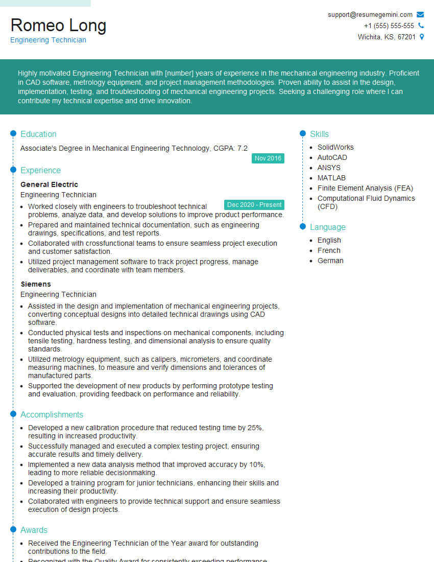
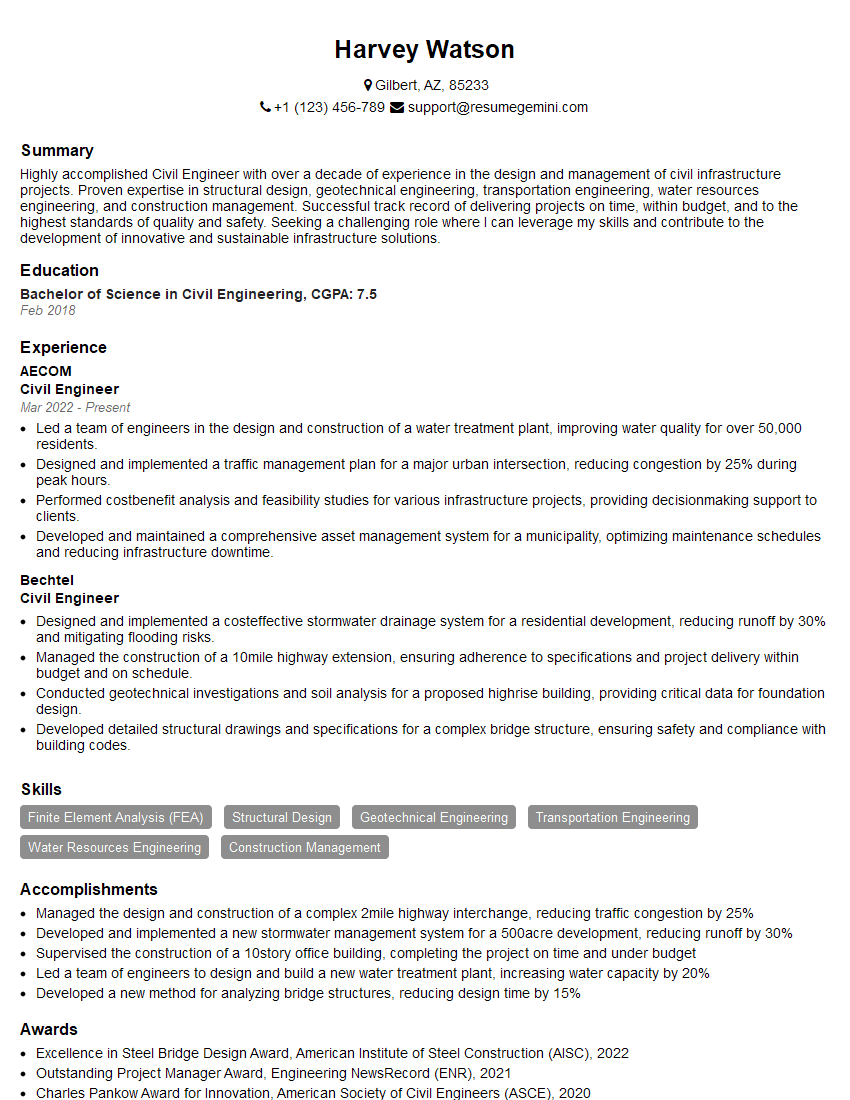
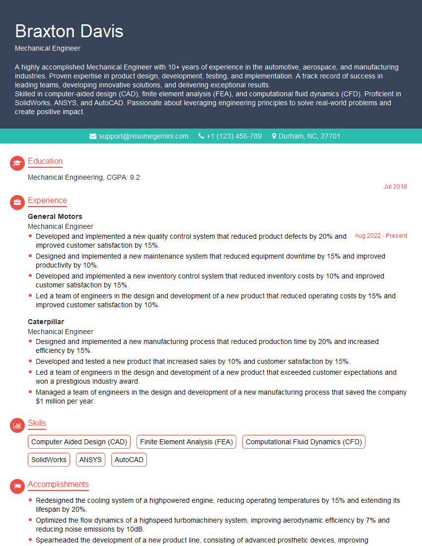
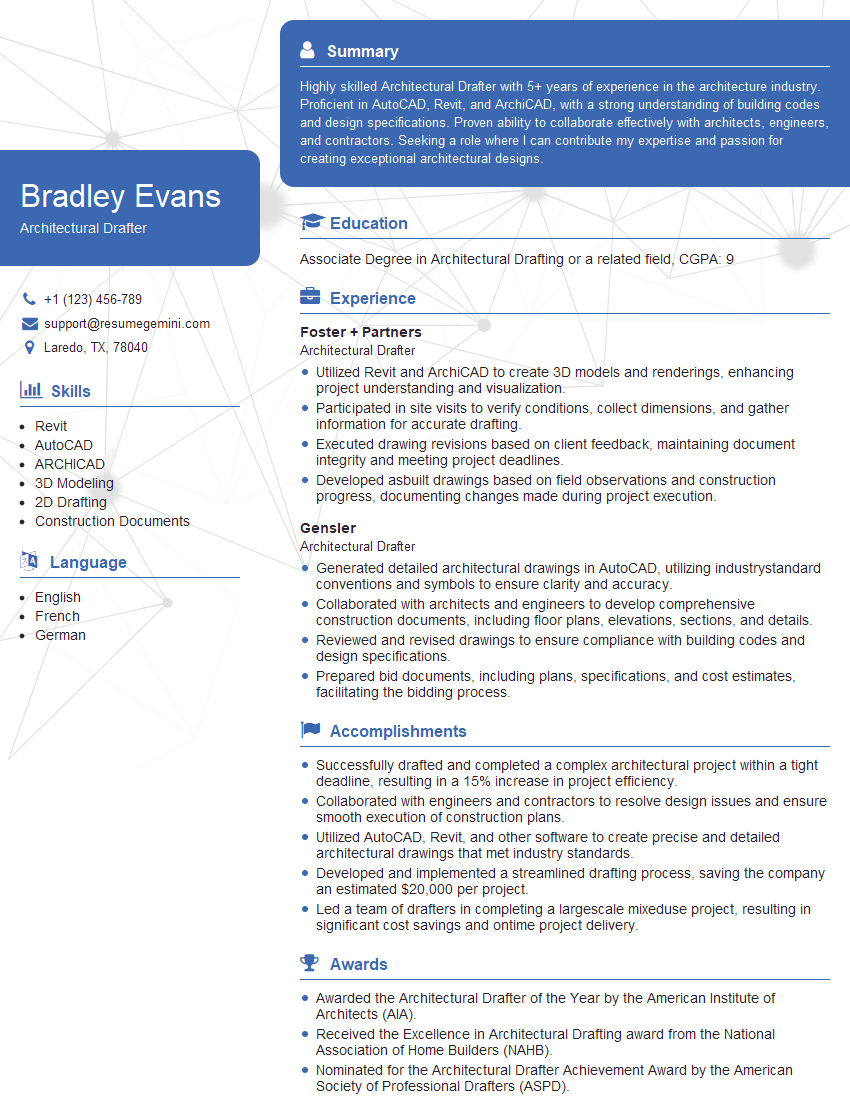
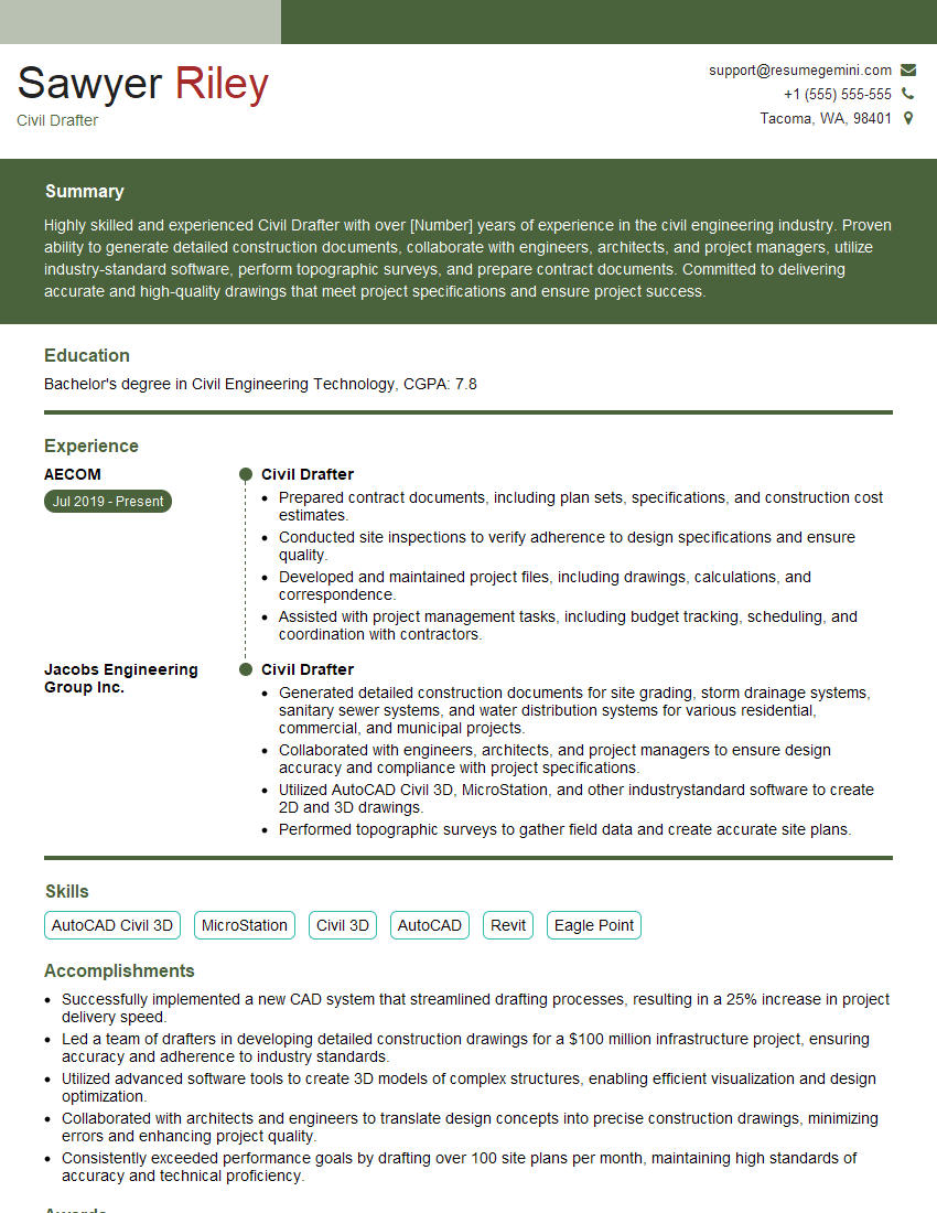
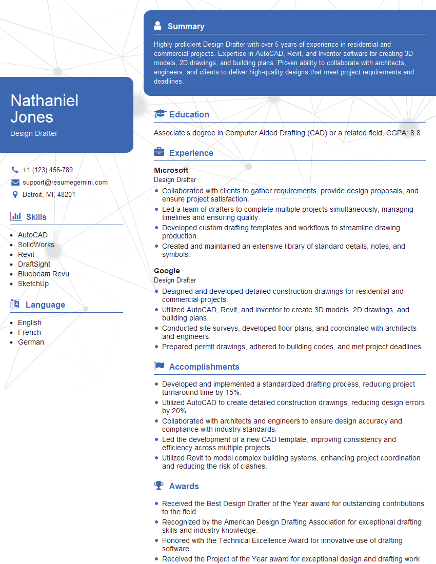
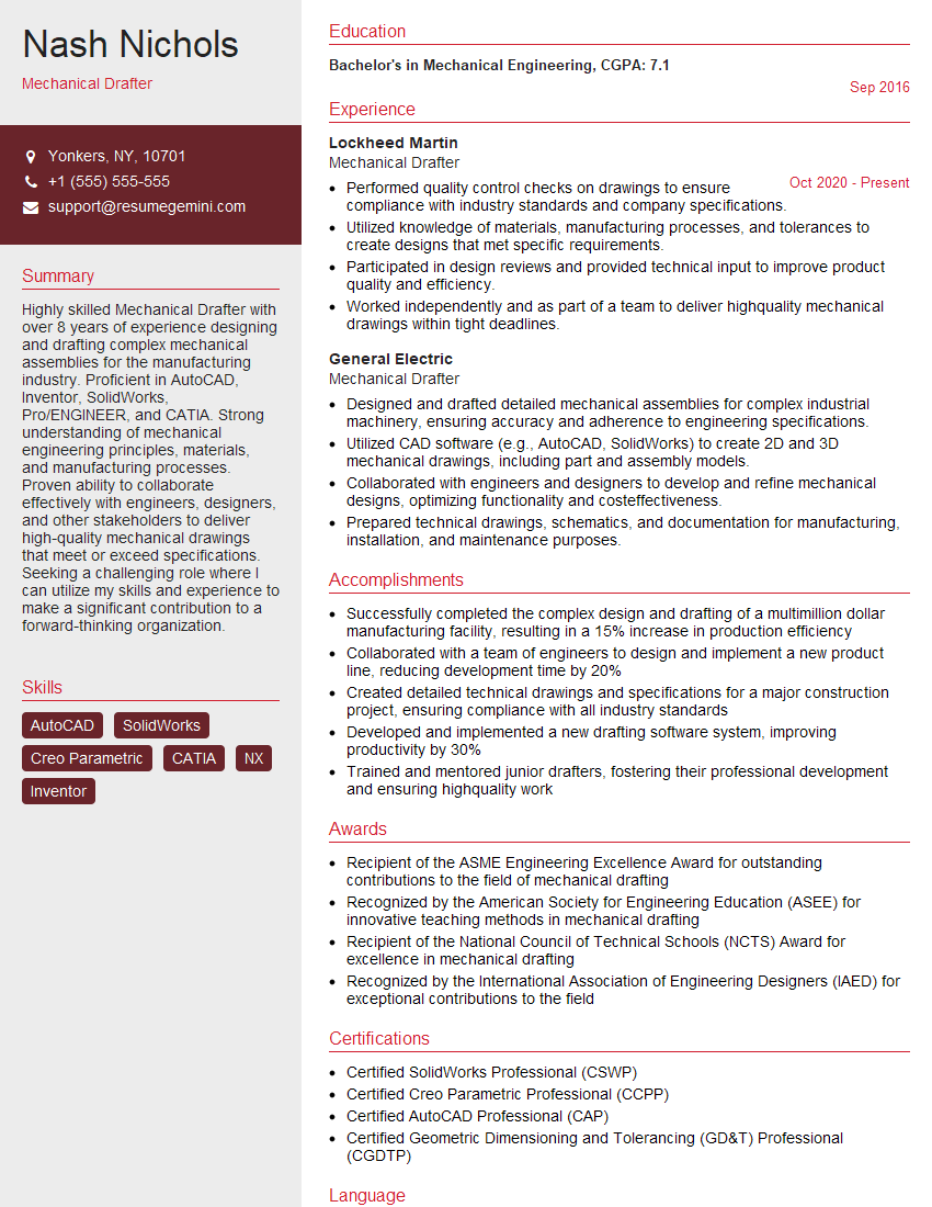
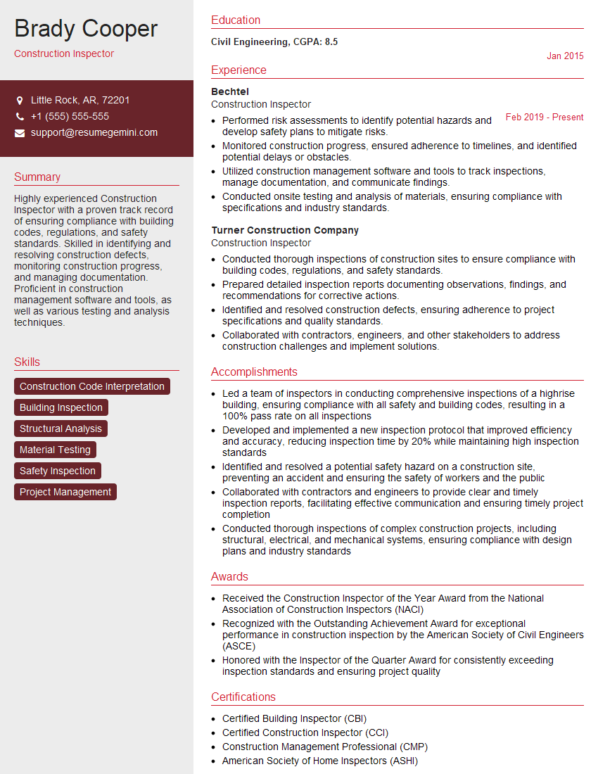
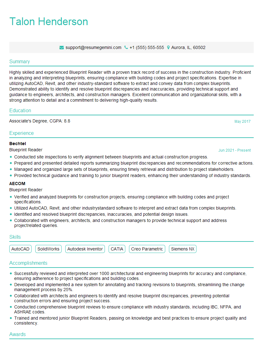
Mastering blueprints and schematic reading is crucial for career advancement in many technical fields, opening doors to exciting opportunities and higher earning potential. A strong understanding of these skills showcases your technical aptitude and problem-solving capabilities – highly valued by employers. To maximize your job prospects, crafting an ATS-friendly resume is essential. This ensures your qualifications are effectively communicated to hiring managers and Applicant Tracking Systems. We highly recommend using ResumeGemini to build a professional and impactful resume. ResumeGemini provides a user-friendly platform to create a compelling document that highlights your skills and experience. Examples of resumes tailored to showcase expertise in Blueprints and Schematic Reading are available to help guide you.
Explore more articles
Users Rating of Our Blogs
Share Your Experience
We value your feedback! Please rate our content and share your thoughts (optional).
What Readers Say About Our Blog
This was kind of a unique content I found around the specialized skills. Very helpful questions and good detailed answers.
Very Helpful blog, thank you Interviewgemini team.

