Cracking a skill-specific interview, like one for Electrical Panel Installation and Maintenance, requires understanding the nuances of the role. In this blog, we present the questions you’re most likely to encounter, along with insights into how to answer them effectively. Let’s ensure you’re ready to make a strong impression.
Questions Asked in Electrical Panel Installation and Maintenance Interview
Q 1. Describe the different types of electrical panels.
Electrical panels, also known as breaker boxes or distribution boards, come in various types, each designed for specific applications and load requirements. The most common types include:
- Main Electrical Panel (Service Panel): This is the primary panel in a building, receiving power from the utility company’s service drop. It distributes power to sub-panels throughout the building.
- Sub-Panel: These panels receive power from a main panel and further distribute power to specific areas of a building, such as a garage or an addition. They offer convenient load management and allow for easier circuit additions or replacements in a smaller area.
- Load Centers: Sometimes used interchangeably with electrical panels, load centers are essentially standardized distribution panels with pre-wired circuit breakers. They often feature a more compact design.
- Meter Panels (Combination Meter and Panel): These panels integrate the electric meter directly into the distribution panel, offering a space-saving and streamlined installation. They’re commonly used in smaller residential or commercial applications.
The choice of panel type depends on the electrical load, building size, and code requirements. A larger home with significant electrical demands, for instance, might require a larger main panel and multiple sub-panels to manage the load efficiently and safely.
Q 2. Explain the NEC code requirements for electrical panel installations.
The National Electrical Code (NEC) mandates stringent safety regulations for electrical panel installations. Key requirements include:
- Proper Sizing: The panel must be appropriately sized to handle the total amperage of all circuits and loads within the building, with sufficient headroom for future expansions.
- Clearances and Accessibility: Adequate space must be provided around the panel for ventilation and easy access for maintenance and repairs. NEC specifies minimum clearances to avoid fire hazards and ensure safe operation.
- Grounding and Bonding: Thorough grounding is crucial to protect against electrical shocks. The NEC outlines specific grounding requirements for the panel itself and all connected circuits.
- Wiring Methods and Materials: The type and size of wiring used to connect the panel to the service and branch circuits must adhere to NEC guidelines based on the amperage rating and location. Proper wire management within the panel is also essential.
- Overcurrent Protection: Circuit breakers or fuses must be properly sized to protect circuits from overload and short circuits. Each circuit must have its own dedicated overcurrent device.
- Installation Location: The panel must be installed in a dry, accessible, and well-ventilated location, often within a designated electrical closet or utility room.
Failure to comply with NEC standards can lead to severe consequences, including electrical fires, electrocution, and significant property damage. It’s crucial for electricians to be thoroughly familiar with and adhere to all applicable code requirements.
Q 3. How do you ensure proper grounding of an electrical panel?
Proper grounding is paramount for safety. It provides a low-resistance path for fault currents to flow to the earth, preventing dangerous voltage buildup and reducing the risk of electrocution. Ensuring proper grounding of an electrical panel involves several key steps:
- Grounding Electrode Conductor (GEC): A heavy gauge copper wire connects the panel’s grounding bar to a grounding electrode, usually a driven ground rod or a metal water pipe. The GEC must be properly sized according to the panel’s amperage rating and the NEC.
- Grounding Bar: The grounding bar within the panel provides a common connection point for all the ground wires in the system. All ground wires from circuits and equipment must be securely connected to this bar.
- Equipment Grounding Conductors (EGCs): These are the individual grounding wires running with each circuit’s hot and neutral wires. They must be properly connected to both the grounding bar in the panel and the equipment grounding terminals.
- Ground Fault Circuit Interrupters (GFCIs): In high-risk locations like bathrooms and kitchens, GFCIs monitor current imbalances and trip the circuit if a ground fault occurs, offering additional protection.
- Bonding: Metallic parts of the electrical system, such as the panel enclosure and metal conduit, must be bonded together to create an equipotential plane, eliminating voltage differences that could cause dangerous shocks.
Regular inspections are essential to ensure the grounding system remains effective. Corrosion or loose connections can compromise grounding integrity, requiring immediate attention.
Q 4. What are the safety precautions for working on an electrical panel?
Working on electrical panels demands utmost caution. Safety must always be the top priority. Here are some essential precautions:
- Lockout/Tagout (LOTO): Before any work begins, always de-energize the panel completely using a LOTO procedure. This involves turning off the main breaker and applying a lock and tag to prevent accidental re-energization.
- Personal Protective Equipment (PPE): Wear appropriate PPE, including insulated gloves, safety glasses, and non-conductive footwear. Never work on energized equipment.
- Proper Tools: Use insulated tools specifically designed for electrical work to avoid accidental shocks.
- Test for Voltage: Before touching any wiring or components, always use a non-contact voltage tester to verify that the circuit is indeed de-energized.
- One Person at a Time: Only one person should work directly on the panel at a time to avoid confusion and potential accidents.
- Awareness of Surroundings: Maintain situational awareness and ensure that no one else can accidentally contact the equipment while working on it.
Ignoring these precautions can lead to serious injury or even death. Never compromise on safety when working with electricity.
Q 5. How do you troubleshoot a faulty circuit breaker?
Troubleshooting a faulty circuit breaker involves systematically identifying the cause of the problem. Here’s a structured approach:
- Visual Inspection: Carefully inspect the breaker for any visible signs of damage, such as scorch marks, loose connections, or broken parts.
- Check the Load: Determine if the circuit is overloaded. Too many appliances or devices drawing high current can trip a breaker.
- Test for Continuity: Using a multimeter, check for continuity between the terminals of the breaker. If the breaker is open (tripped), it will show infinite resistance. If closed, it shows near-zero resistance.
- Check for Short Circuits: A short circuit can also trip a breaker. This requires careful testing of the wiring connected to the circuit.
- Look for Loose Connections: Loose connections on the breaker or at the wiring terminals can create high resistance and cause overheating. Tighten these connections securely but don’t overtighten.
- Inspect the Wiring: Examine the wiring connected to the breaker for any signs of damage, such as fraying, cuts, or insulation breakdown.
If you’re unable to identify the problem, it’s best to call a qualified electrician to avoid further damage or risk of injury.
Q 6. Explain the process of replacing a faulty circuit breaker.
Replacing a faulty circuit breaker is a relatively straightforward process, but safety remains paramount. Always follow the LOTO procedure before starting.
- Turn Off the Breaker: Completely switch off the breaker you intend to replace. Verify it is OFF using a voltage tester.
- Remove the Breaker: Depending on the panel type, you might need to push a release lever or push the breaker slightly to release it from its position in the panel.
- Inspect the Wiring: Examine the wiring carefully before disconnecting it. Make note of the position and connection of the wires.
- Disconnect the Wires: Carefully disconnect the wires from the terminals of the faulty breaker.
- Install the New Breaker: Insert the new breaker of the same amperage rating into the panel, ensuring proper alignment.
- Connect the Wires: Connect the wires to the terminals of the new breaker, making sure each wire is securely fastened. Consult the manufacturer’s wiring diagram if needed.
- Turn On the Breaker: Turn on the breaker and verify functionality by plugging in an appliance or device on that circuit. If it still fails to turn on or trips immediately, the issue may not be isolated to the breaker, and further troubleshooting is necessary.
Always use a breaker with the correct amperage rating for the circuit. Incorrect ratings can cause fire hazards or damage to equipment. If unsure, consulting a professional is always the safest course of action.
Q 7. How do you identify and address overcurrent protection issues?
Overcurrent protection is essential to prevent circuit overload and short circuits which can lead to fires and equipment damage. Addressing these issues involves:
- Identifying the Cause: Determine the root cause of the overcurrent situation. This could be an overloaded circuit, a short circuit, or a faulty appliance.
- Using Circuit Breakers: Circuit breakers are designed to automatically trip when excess current flows through a circuit. A tripped breaker indicates an overcurrent condition and needs to be investigated.
- Inspecting Wiring and Connections: Check the wiring for any signs of damage, such as loose connections, frayed wires, or insulation breakdown. These defects can cause short circuits and overcurrent conditions.
- Checking Appliance Ratings: Ensure that all appliances and devices on the circuit are within the circuit’s amperage rating. Overloading a circuit by connecting too many high-power devices can easily trigger a breaker.
- Using Fuses (less common in newer installations): Fuses are similar to circuit breakers but are one-time use devices. When a fuse blows, it indicates an overcurrent condition, requiring the fuse to be replaced with one of the same rating.
- Correcting the Problem: Once the root cause is identified, address the problem correctly. This could involve replacing faulty appliances, repairing damaged wiring, re-routing circuits to better balance the load, or upgrading the panel to increase its capacity.
Ignoring overcurrent protection issues can have disastrous consequences. Regular inspections and proactive maintenance are key to preventing these problems before they become dangerous.
Q 8. What are the common causes of electrical panel failures?
Electrical panel failures stem from a variety of issues, often interconnected. Think of it like a car – many small problems can lead to a major breakdown. Common culprits include:
Overloading: Drawing more current than the panel’s capacity allows. This is like trying to fit too many passengers into a small car – it’s going to overload the system. Common causes are adding too many appliances or high-draw equipment without upgrading the panel.
Loose Connections: Over time, vibrations and heat can loosen connections, leading to arcing and overheating. Imagine a wobbly wire in a lamp – it’s a fire hazard waiting to happen. Regular tightening is crucial.
Faulty Breakers or Wiring: Defective breakers fail to trip when overloaded, leading to potential fires. Similarly, damaged wiring can cause shorts and overloads. This is like a faulty brake system in your car – catastrophic consequences can ensue.
Environmental Factors: Exposure to moisture or extreme temperatures can degrade components, causing premature failure. Just as rust damages a car’s body, humidity can corrode electrical components.
Age and Wear: Panels wear out over time, with components becoming less reliable. Like an old car, regular maintenance extends its lifespan, but eventually, replacement is necessary.
Identifying the root cause is vital for preventing future failures and ensuring safety.
Q 9. Describe your experience with different types of busbars.
My experience encompasses a range of busbars, each with its own advantages and disadvantages. I’ve worked extensively with copper and aluminum busbars, the most common materials. Copper offers superior conductivity, but is more expensive. Aluminum is cost-effective but requires more careful installation and attention to oxidation. I’ve also encountered various configurations, including:
Solid Busbars: These are simple, reliable, and commonly used in smaller panels.
Copper Clad Aluminum Busbars: These combine the cost-effectiveness of aluminum with the conductivity of copper, offering a good balance of performance and price.
Modular Busbars: These are more adaptable, allowing for easier upgrades and expansion.
The selection of a busbar type depends on the panel’s size, amperage rating, and budget considerations. Careful selection and installation are paramount to ensure safety and longevity.
Q 10. How do you calculate the ampacity of a circuit?
Calculating circuit ampacity involves several factors. Ampacity is the maximum current a conductor can carry continuously without exceeding its temperature rating. Think of it as the ‘speed limit’ for your electrical circuit.
The primary calculation considers the conductor’s size (gauge) and material (copper or aluminum), along with the installation conditions such as ambient temperature, type of conduit, and number of conductors in the conduit. These factors are often found in electrical codes and manufacturer’s specifications. You can also use readily available online calculators and software that handle these calculations more accurately.
For example, a 12-gauge copper wire in free air has a higher ampacity than the same wire enclosed in conduit, because heat dissipation is less effective in a conduit. Codes like the National Electrical Code (NEC) provide detailed tables and formulas to determine appropriate ampacity for different scenarios. Ignoring these rules can result in dangerously overloaded circuits.
Q 11. Explain the different types of electrical panel enclosures.
Electrical panel enclosures are designed to protect internal components from environmental hazards and accidental contact. Common types include:
Metal Enclosures: These are typically made of steel or aluminum and offer robust protection against physical damage and environmental factors.
NEMA-Rated Enclosures: These enclosures meet specific standards (NEMA 1, NEMA 3R, NEMA 4X, etc.) that define their protection against environmental factors such as rain, dust, and corrosion. The rating indicates the level of protection offered.
Non-Metallic Enclosures: These are often made from plastic or fiberglass and are lighter than metal enclosures but may offer less protection against physical impacts.
The choice of enclosure depends on the application’s environmental conditions and safety requirements. For example, an outdoor panel would require a NEMA-rated enclosure to withstand the elements.
Q 12. What are the requirements for labeling and identification in an electrical panel?
Clear and accurate labeling is crucial for safety and efficient maintenance. The NEC specifies requirements for labeling and identification within electrical panels. Key aspects include:
Circuit Breakers: Each breaker must be clearly labeled to identify the circuit it protects (e.g., ‘Kitchen Outlets,’ ‘Bathroom Lighting’).
Wiring: Wiring should be labeled at both ends to indicate its destination. This is particularly important in complex panels.
Panel Identification: The panel itself should be labeled with information like the building address, panel number, and date of installation.
Legend/Schematic: A panel legend or schematic can be incredibly helpful, especially in larger panels, to visually show the circuit layout and wiring.
Using standardized labeling practices, such as color-coding and consistent terminology, enhances comprehension and simplifies troubleshooting.
Q 13. How do you inspect an electrical panel for safety hazards?
Inspecting an electrical panel for safety hazards requires a systematic approach. Always de-energize the panel before performing any inspection – this is non-negotiable! My inspection process includes:
Visual Inspection: Look for signs of overheating (scorching, discoloration), loose connections, damaged wiring, and corrosion.
Breaker Check: Verify that breakers are properly seated and trip mechanisms function correctly. Test tripping by simulating an overload.
Wiring Integrity: Examine wiring for damage, frayed insulation, or improper routing.
Busbar Condition: Inspect busbars for any signs of arcing, pitting, or overheating.
Grounding and Bonding: Verify proper grounding and bonding connections.
Any questionable findings necessitate further investigation or professional remediation. Ignoring even minor issues can escalate into major safety hazards.
Q 14. Describe your experience with arc flash safety procedures.
Arc flash safety procedures are paramount when working on energized electrical equipment. Arc flash is a sudden, powerful explosion of electrical energy that can cause severe burns, blindness, and even death. My experience includes rigorous adherence to safety protocols, such as:
Arc Flash Risk Assessment: Before starting any work, a thorough risk assessment must be conducted to determine the potential arc flash hazard and necessary PPE (Personal Protective Equipment).
Lockout/Tagout (LOTO): Always implement LOTO procedures to prevent accidental energization during maintenance or repair. This is the most critical safety measure.
Personal Protective Equipment (PPE): Wearing appropriate PPE, including arc flash suits, face shields, insulated gloves, and hearing protection, is mandatory when working on energized equipment.
Training and Competence: Only trained and qualified personnel should work on energized electrical systems. Continuous training is vital to keep knowledge and skills up-to-date.
Appropriate Tools: Insulated tools designed to withstand high voltages are crucial.
Arc flash safety is not simply following rules; it’s a mindset prioritizing safety above all else. Neglecting these procedures can have devastating consequences.
Q 15. How do you ensure proper wire sizing and termination in an electrical panel?
Proper wire sizing and termination in an electrical panel are paramount for safety and efficient operation. Undersized wires overheat, posing a fire hazard, while oversized wires are wasteful. Termination, the process of securely connecting wires to devices, must be flawless to prevent loose connections, which can lead to arcing and potential fires.
We determine wire size based on the amperage draw of the circuit, using established electrical codes like the NEC (National Electrical Code). For example, a 20-amp circuit requires at least 12 AWG (American Wire Gauge) copper wire. We then carefully strip the wire insulation, ensuring we don’t nick the conductor, and firmly insert the wire into the terminal, ensuring the connection is snug. I always use a torque wrench to ensure proper tightening – this prevents over-tightening, which can damage the wire, and under-tightening, which can create a loose connection. Finally, we visually inspect the connection to confirm it is secure and correctly terminated. Improper termination might look like a wire not fully seated in the terminal or a visible gap between the wire and terminal lug. We would immediately correct any such issues, ensuring a strong, reliable connection.
Crimp connectors are also used, especially in high-vibration environments or with stranded wire. The crimp connectors, when properly selected and crimped with the appropriate tool, offer a very safe and reliable method of termination.
Career Expert Tips:
- Ace those interviews! Prepare effectively by reviewing the Top 50 Most Common Interview Questions on ResumeGemini.
- Navigate your job search with confidence! Explore a wide range of Career Tips on ResumeGemini. Learn about common challenges and recommendations to overcome them.
- Craft the perfect resume! Master the Art of Resume Writing with ResumeGemini’s guide. Showcase your unique qualifications and achievements effectively.
- Don’t miss out on holiday savings! Build your dream resume with ResumeGemini’s ATS optimized templates.
Q 16. Explain the process of adding a new circuit to an existing panel.
Adding a new circuit to an existing panel is a straightforward process, but safety is paramount. First, we always ensure the panel is properly de-energized and locked out/tagged out. Then, we assess the panel’s capacity – is there sufficient space for a new breaker and are there enough available busbars? If not, upgrading to a larger panel might be necessary. Next, we choose a breaker appropriate for the intended load (lighting, appliance, etc.) and size the wiring accordingly based on NEC standards.
Next, we carefully route the new wiring through the conduit and into the panel, securing the wires and following appropriate routing and termination standards. The wire is then securely connected to the breaker using proper techniques (as mentioned in the previous answer) and the breaker is installed into the panel. Finally, we restore power and test the new circuit using a voltage tester, ensuring it functions correctly. We might use a dedicated circuit breaker for high-power appliances to avoid overloading a general purpose circuit. Always double checking our work and making sure all the terminations are visually sound before we energize the circuit.
Q 17. How do you handle situations involving locked-out/tagged-out procedures?
Locked-out/tagged-out (LOTO) procedures are non-negotiable for electrical panel work. These procedures ensure that electrical energy is completely isolated and the equipment remains locked out to prevent accidental energization. Before any work begins, the panel must be completely de-energized, and a LOTO device (lock and tag) is placed on the main disconnect. This is a legally binding safety measure. Only authorized personnel with the appropriate key or tag removal authorization may remove the lock.
I’ve been involved in numerous projects where LOTO has prevented potentially hazardous situations. I always ensure that everyone on the team understands and follows the LOTO procedures meticulously. I’ve had instances where the lockout was mistakenly bypassed or a tag was missing and I took immediate action to resolve the situation, ensuring the safety and compliance of the team. It’s not just a procedure; it’s a critical part of our safety culture.
Q 18. Describe your experience with various types of panel meters and monitoring devices.
I have extensive experience with various panel meters and monitoring devices, including clamp meters (for measuring current without disconnecting the wire), digital multimeters (DMMs) for measuring voltage, current, and resistance, power meters to measure power consumption, and energy monitoring systems that track energy use over time. These devices allow for both real-time monitoring and historical data analysis.
For instance, we use clamp meters routinely for troubleshooting and verifying circuit loads. If a breaker trips frequently, we’ll use a clamp meter to determine the actual current draw to check if it’s exceeding the breaker’s rating. Energy monitoring systems provide valuable data for optimizing energy efficiency and identifying potential problems before they lead to failures. They can help identify energy waste in lighting systems or equipment, leading to cost-saving solutions. DMM’s are essential for troubleshooting and testing individual circuits.
Q 19. What is your experience with different types of circuit breakers (e.g., thermal-magnetic, electronic)?
I’m proficient with various circuit breaker types. Thermal-magnetic breakers are the most common, offering protection against both overcurrent (due to excessive heat) and short circuits (due to magnetic forces). Electronic circuit breakers offer more advanced features, like adjustable trip curves and communication capabilities which allow for integration with building management systems.
The choice depends on the application. For standard residential applications, thermal-magnetic breakers are usually sufficient. However, in industrial settings or for critical loads, electronic breakers may offer better protection and monitoring. I’ve worked with numerous brands and types, ensuring the correct breaker is selected for the specific application and load requirements – this ensures the highest level of safety and protection for the circuit.
Q 20. How do you ensure proper torque when tightening connections in a panel?
Proper torque when tightening connections is crucial to avoid loose connections and potential hazards. Using a torque wrench is not optional; it’s a standard procedure in professional panel installations and maintenance. Each terminal has a specified torque value, typically found in the manufacturer’s instructions or readily available in various online resources. This value ensures the connection is secure without damaging the wire or terminal.
Failure to use a torque wrench can result in over-tightening, which can strip the screw or damage the wire, or under-tightening, creating a loose connection which can cause heating and potential fire hazards. Over-tightening is often worse than under tightening due to the potential for permanent damage to the equipment. I would never install an electrical panel without a torque wrench in my tool bag.
Q 21. Describe your familiarity with different types of grounding systems.
I’m familiar with various grounding systems, including grounding electrode system (GES) that involves driving a ground rod into the earth, grounding electrode conductor (GEC) which connects the system to the ground rod, and equipment grounding conductor (EGC) which provides a low-impedance path to the ground to minimize electrical shock hazards. I understand the importance of proper grounding for safety and equipment protection. The NEC provides specific requirements for grounding systems.
Different grounding systems are used depending on the application and local codes. Proper grounding is essential to protect against electrical shocks and prevent damage to equipment. A faulty grounding system can lead to dangerous voltage levels on equipment casings, potentially causing shocks. I ensure all installations comply with the applicable codes, meticulously verifying the continuity of the ground path using a multimeter.
Q 22. What is your experience with working on three-phase electrical panels?
Three-phase electrical panels are essential in higher-power applications, supplying power to larger commercial or industrial settings. My experience encompasses the complete lifecycle, from initial design review and installation to ongoing maintenance and troubleshooting. I’ve worked extensively with various configurations, including delta and wye systems, and am proficient in calculating loads, sizing conductors, and ensuring proper grounding and bonding. For instance, I recently worked on a project upgrading a 480V, three-phase panel in a manufacturing plant, requiring careful coordination with the facility’s operations to minimize downtime.
I’m comfortable with different types of breakers, including molded-case circuit breakers (MCCBs) and air circuit breakers (ACBs), and understand the nuances of their operation and testing. My experience also extends to working with various protective relaying schemes commonly found in three-phase systems, ensuring efficient and safe power distribution.
Q 23. How do you diagnose and repair problems with panel wiring?
Diagnosing panel wiring problems begins with a thorough visual inspection, checking for loose connections, damaged insulation, or signs of overheating. I use a multimeter to test voltage, current, and continuity across different sections of the wiring. For example, I might check for continuity to verify that a circuit is complete and not interrupted by a broken wire. A low-voltage test can pinpoint a weak connection or high resistance in the circuit. I also utilize specialized equipment like a clamp meter to measure current draw without interrupting the circuit.
Repairs range from simple tightening of loose screws to replacing damaged wires or components. Safety is paramount – always de-energize the panel before working on it. After repairs, I always rigorously test the circuit to ensure its integrity before re-energizing the panel. Detailed documentation, including photographs and descriptions of the work performed, is crucial for traceability and future maintenance.
Q 24. Describe your troubleshooting process for electrical panel problems.
My troubleshooting process is systematic and follows a clear methodology. It begins with understanding the problem: What is not working? What are the symptoms? Next, I perform a visual inspection, looking for obvious issues like tripped breakers or loose connections. I then use diagnostic tools – multimeters and clamp meters are my go-to – to measure voltage, current, and continuity. I proceed logically through the circuit, isolating potential problem areas.
For example, if a circuit is not working, I’ll check the breaker first, then the wiring to the load, ensuring all connections are secure and the wire itself isn’t damaged. If the problem is more complex, I may use a thermal imager to detect hotspots indicating overheating, a potential sign of a faulty component or high resistance in a joint. Throughout this process, safety remains a top priority. I always de-energize the circuit before direct contact with any live components. Finally, thorough testing and documentation complete the troubleshooting process.
Q 25. What is your experience with preventative maintenance of electrical panels?
Preventative maintenance is critical for extending the life of electrical panels and preventing costly downtime. My approach includes regular inspections, checking for loose connections, corrosion, and signs of overheating. I test all breakers to ensure they trip properly. I also inspect the busbars for any signs of damage or arcing. Cleaning the panel of dust and debris is also important, as it prevents overheating and potential fire hazards.
For example, I perform infrared thermal imaging scans to detect potential overheating problems before they escalate into larger issues. I also check the grounding system to ensure its integrity. A detailed log of all inspections and maintenance activities is kept, facilitating predictive maintenance strategies and improving operational efficiency. Regular preventative maintenance can significantly reduce the likelihood of unexpected failures and ensure the continued safe operation of the electrical system.
Q 26. How do you manage and organize your work efficiently on an electrical panel job?
Efficient work on an electrical panel job relies on meticulous planning and organization. Before starting, I ensure I have all the necessary tools and materials. A well-organized workspace is crucial for safety and efficiency. I use labeled containers and clearly marked areas to keep things organized. I carefully review the blueprints and schematics to understand the layout and functionality of the panel.
I often use a checklist to ensure that all steps are followed systematically. This checklist includes safety procedures like lockout/tagout before working on live components. Prioritization of tasks is key, starting with critical safety-related aspects before proceeding to other tasks. Effective communication with colleagues and clients keeps the project on track, ensuring everyone is aware of the progress and any potential challenges.
Q 27. What are your preferred methods for documenting electrical panel work?
Documentation is a vital part of any electrical panel work. I use a combination of methods for accurate and complete records. This includes detailed written reports, capturing the scope of work, findings during inspections, repairs or replacements made, and test results. Photographs and videos are crucial, documenting the conditions before, during, and after the work. I also utilize digital tools for organizing schematics and updating panel diagrams after modifications.
For instance, I might use specialized software to create as-built drawings reflecting changes made during installation or maintenance. Clear and concise labelling of components and wiring, both in physical installations and digital documentation, is key to easy future maintenance and troubleshooting. This thorough documentation ensures the project’s safety, allows easy tracking of completed work, and provides crucial information for future maintenance needs.
Key Topics to Learn for Electrical Panel Installation and Maintenance Interview
- National Electrical Code (NEC) Compliance: Understanding and applying relevant NEC articles for safe and compliant installations. This includes grounding, bonding, and overcurrent protection.
- Panel Sizing and Load Calculations: Determining appropriate panel size based on load requirements, future expansion needs, and service capacity. Practical application involves calculating branch circuit loads and determining the main breaker size.
- Wiring Methods and Techniques: Familiarity with various wiring methods (e.g., conduit bending, cable tray installation) and proper termination techniques for different wire types and sizes. This also includes understanding proper wire sizing for different loads.
- Troubleshooting and Diagnostics: Identifying and resolving common electrical panel issues, such as blown fuses, tripped breakers, and loose connections. This involves using diagnostic tools and applying systematic troubleshooting approaches.
- Safety Procedures and Regulations: Adhering to strict safety protocols, including lockout/tagout procedures, arc flash mitigation, and personal protective equipment (PPE) usage. Understanding OSHA regulations is crucial.
- Types of Electrical Panels and Components: Knowledge of various panel types (e.g., load centers, switchboards) and their components (e.g., breakers, busbars, metering devices). Understanding the function of each component is key.
- Preventive Maintenance and Inspection: Performing routine inspections and preventative maintenance to ensure panel integrity and prevent failures. This includes cleaning, tightening connections, and identifying potential hazards.
- Documentation and Reporting: Maintaining accurate records of installations, maintenance activities, and any identified issues. This is crucial for tracking work and ensuring compliance.
Next Steps
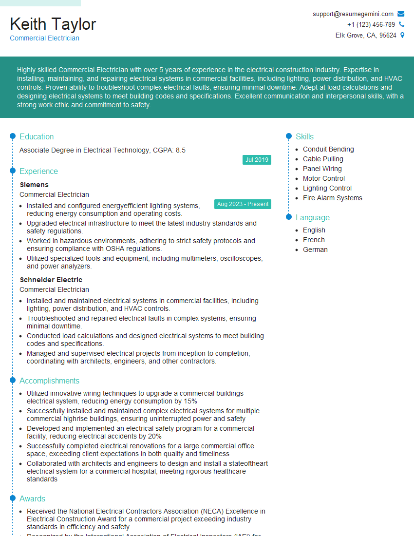
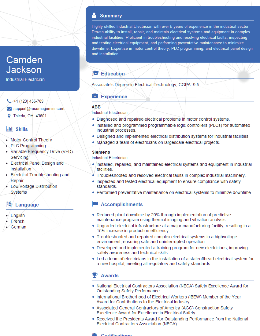
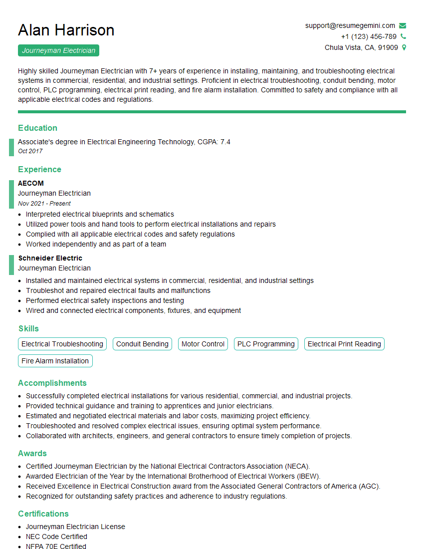
Mastering Electrical Panel Installation and Maintenance is vital for a successful and rewarding career in the electrical industry. It opens doors to diverse roles with excellent growth potential. To maximize your job prospects, invest time in creating a compelling, ATS-friendly resume that highlights your skills and experience effectively. ResumeGemini is a trusted resource to help you build a professional resume that stands out. They provide examples of resumes tailored to Electrical Panel Installation and Maintenance roles, giving you a head start in your job search.
Explore more articles
Users Rating of Our Blogs
Share Your Experience
We value your feedback! Please rate our content and share your thoughts (optional).
What Readers Say About Our Blog
To the interviewgemini.com Webmaster.
Very helpful and content specific questions to help prepare me for my interview!
Thank you
To the interviewgemini.com Webmaster.
This was kind of a unique content I found around the specialized skills. Very helpful questions and good detailed answers.
Very Helpful blog, thank you Interviewgemini team.
