Unlock your full potential by mastering the most common Electrical systems installation and repair interview questions. This blog offers a deep dive into the critical topics, ensuring you’re not only prepared to answer but to excel. With these insights, you’ll approach your interview with clarity and confidence.
Questions Asked in Electrical systems installation and repair Interview
Q 1. Explain the National Electrical Code (NEC) and its significance in electrical installations.
The National Electrical Code (NEC) is a widely adopted standard for the safe installation of electrical wiring and equipment in the United States. It’s essentially a rulebook ensuring electrical systems are designed and built to prevent fires, shocks, and other hazards. Think of it as the bible for electricians. It’s not a law itself, but most jurisdictions adopt it as part of their building codes, making compliance mandatory.
Its significance lies in its ability to establish a baseline for safety. By following the NEC, we minimize the risk of electrical accidents and ensure long-term reliability of electrical systems. It covers everything from wiring methods and circuit protection to grounding requirements and the installation of specific equipment. For example, it specifies the appropriate gauge of wire for different amperage levels, preventing overheating and potential fires. Failure to comply with the NEC can result in fines, insurance issues, and, most importantly, serious injury or death.
Q 2. Describe the process of troubleshooting a faulty circuit breaker.
Troubleshooting a faulty circuit breaker involves a systematic approach to identify the root cause. First, always ensure your safety by turning off the main power breaker before starting any work. Never assume anything!
Step 1: Visual Inspection: Begin by carefully examining the circuit breaker itself. Look for any signs of damage, such as scorch marks, loose connections, or a tripped breaker (the switch is in the ‘off’ position).
Step 2: Check the Load: If the breaker is tripped, determine what appliances or circuits are connected to that particular breaker. A simple overload (too many appliances drawing too much power) is the most common cause of a tripped breaker. Unplug some devices on that circuit to see if it resets.
Step 3: Test for Shorts: If the breaker trips immediately after resetting with a minimal load, there’s likely a short circuit in the wiring. This requires a more in-depth investigation possibly using a multimeter to check for continuity and identify the faulty section of wiring.
Step 4: Check for Ground Faults: If you suspect a ground fault, use a ground fault tester, or a non-contact voltage tester. A ground fault could indicate a dangerous condition where current is leaking to ground.
Step 5: If Unsure, Call a Professional: If you’re not comfortable performing these tests or you cannot identify the problem, it’s crucial to call a qualified electrician. Working with electricity can be extremely dangerous, and it’s better to err on the side of caution.
Q 3. What are the different types of wiring methods, and when would you use each?
Several wiring methods exist, each suited to different applications and environments. The choice depends on factors like building construction, cost, and ease of installation.
- Romex (NM-B): This is a common non-metallic sheathed cable used in residential settings. It’s relatively easy to install, cost-effective, and suitable for less demanding applications. However, it’s not as robust as other options and requires protection from physical damage.
- BX (AC Cable): This armored cable uses a flexible metal sheath for added protection against physical damage. It’s suitable for areas where the cable might be subject to more abuse, such as garages or basements. Installation is slightly more challenging than Romex.
- Rigid Conduit (IMC or EMT): These metallic conduits offer superior protection and are commonly used in commercial and industrial settings. They are more durable, provide better grounding, and are ideal for environments with high risk of mechanical stress or potential fire hazards. However, installation is more labor-intensive.
- Flexible Conduit (Liquidtight): This is used in locations exposed to moisture or where flexibility is important. Think outdoor applications or locations subject to vibrations.
The selection process is critical for safety and compliance with the NEC. Incorrect wiring methods can lead to electrical hazards, fire risks, and costly repairs.
Q 4. How do you ensure electrical safety during installation and maintenance?
Ensuring electrical safety during installation and maintenance is paramount. It’s not just about following the NEC; it’s about developing a safety-first mindset.
- Lockout/Tagout Procedures: Always de-energize circuits before working on them. Use lockout/tagout devices to prevent accidental re-energization. This prevents potentially fatal shocks.
- Personal Protective Equipment (PPE): Always wear appropriate PPE, including safety glasses, insulated gloves, and safety shoes. These protect against shocks, arc flash, and other potential injuries.
- Proper Tools and Techniques: Use the right tools for the job, ensuring they’re in good condition and properly insulated. Follow established wiring practices, ensuring connections are secure and properly grounded.
- Regular Inspections: Periodically inspect electrical systems for signs of damage, loose connections, or overheating. Early detection of potential hazards can prevent major problems.
- Knowledge of the NEC: Stay updated on the NEC and apply its provisions meticulously. Understanding the code is essential for safe and compliant installations.
I always emphasize that a little extra time spent on safety is always worth it. A rushed job can have devastating consequences.
Q 5. Explain the function of a Ground Fault Circuit Interrupter (GFCI).
A Ground Fault Circuit Interrupter (GFCI) is a life-saving device designed to protect against electrical shocks. It works by constantly monitoring the balance of current flowing in and out of a circuit. If even a small imbalance (as little as 5 milliamperes) is detected—indicating a ground fault, where current is leaking to ground—the GFCI rapidly interrupts the power, preventing a potentially fatal shock. Imagine a scenario where someone touches a faulty appliance—a GFCI will immediately cut off the power, preventing electrocution.
GFCIs are commonly found in bathrooms, kitchens, garages, and outdoor outlets because these locations are near water sources or exposed to the elements, increasing the risk of ground faults. They’re essential safety devices that have saved countless lives.
Q 6. Describe your experience with different types of electrical motors.
My experience encompasses various types of electrical motors, including:
- AC Induction Motors: These are the workhorses of many industrial applications, known for their robustness, simplicity, and relatively low cost. I’ve worked extensively with single-phase and three-phase induction motors in various horsepower ratings, troubleshooting issues like starting problems, overheating, and mechanical failures.
- DC Motors: While less common than AC motors, DC motors are often used in applications requiring precise speed control or high starting torque, such as robotics or specialized machinery. I have experience with both brushed and brushless DC motors and the associated control systems.
- Servomotors: I’ve worked with servomotors in automated systems, understanding their precise control capabilities and integration with feedback systems. Troubleshooting these motors often involves checking encoder signals and control circuitry.
- Stepper Motors: These motors are used in applications demanding precise positional control, like 3D printers or CNC machines. I have experience with diagnosing and repairing issues related to step loss or erratic movement.
My experience spans both troubleshooting existing motor systems and specifying and installing new motor systems, ensuring proper selection based on load requirements, voltage, and application-specific needs.
Q 7. How do you test for continuity and voltage?
Testing for continuity and voltage is fundamental in electrical troubleshooting. A multimeter is the essential tool for these tests.
Continuity Test: This test checks for the presence of a complete electrical path. Set the multimeter to the continuity setting (usually represented by a diode symbol). Place the probes across the components or wires you want to test. A continuous beep or a reading near zero ohms indicates a complete circuit. This is useful for checking if a wire is broken or a switch is closed. For example, I might use this to check the continuity of a wire before connecting it to a load.
Voltage Test: This test measures the electrical potential difference between two points in a circuit. Set the multimeter to the appropriate voltage range (AC or DC, depending on the circuit). Carefully place the probes across the points you are testing. Ensure the range selected on the meter is higher than the expected voltage to prevent damage to the meter. The reading displays the voltage present. For instance, I might use this to ensure 120VAC is present at an outlet before connecting a device.
Safety is paramount during these tests. Always de-energize circuits when possible and use insulated probes. Never touch exposed wires or components while testing.
Q 8. What are the safety precautions you take when working with high-voltage systems?
Safety is paramount when working with high-voltage systems. A single mistake can be catastrophic. My approach always begins with a thorough risk assessment, identifying potential hazards and developing a safe work plan. This includes de-energizing the system completely whenever possible, using lockout/tagout procedures to prevent accidental re-energization. If de-energizing isn’t feasible, I utilize appropriate personal protective equipment (PPE), such as insulated gloves, rubber mats, and safety glasses. I also employ voltage testers to confirm de-energization before touching any components and utilize insulated tools to maintain a safe working distance. Furthermore, I always work with a partner, ensuring constant communication and mutual observation. We follow strict safety protocols, and a comprehensive post-job inspection is crucial to confirm everything is safe and functioning correctly.
For example, recently, I was working on a high-voltage transformer. Before starting any work, we de-energized the transformer, locked out the circuit breaker, and tagged it with warning labels. After double-checking with a voltage tester, we then proceeded with our maintenance.
Q 9. Explain the difference between AC and DC current.
The core difference between AC (Alternating Current) and DC (Direct Current) lies in the direction of electron flow. In DC, electrons flow consistently in one direction, like a river flowing downstream. This is the type of current produced by batteries. AC, on the other hand, periodically reverses the direction of electron flow, oscillating back and forth. Think of it like a wave in the ocean, constantly changing direction. This is the current supplied by power plants to homes and businesses. The frequency of this oscillation is typically 50 or 60 Hertz (Hz), meaning the direction changes 50 or 60 times per second.
AC current is more efficient for long-distance power transmission due to the ease of stepping up and down voltage using transformers. DC current, while simpler in nature, is better suited for applications requiring constant voltage, like charging batteries or powering electronic devices.
Q 10. How do you calculate voltage, current, and resistance using Ohm’s Law?
Ohm’s Law describes the relationship between voltage (V), current (I), and resistance (R) in an electrical circuit. The formula is: V = I * R
This means voltage is equal to the current multiplied by the resistance. We can rearrange this formula to solve for any of the three variables:
I = V / R(Current equals voltage divided by resistance)R = V / I(Resistance equals voltage divided by current)
For example, if a circuit has a voltage of 12 volts and a resistance of 4 ohms, the current would be: I = 12V / 4Ω = 3 Amps
Understanding Ohm’s Law is fundamental to electrical troubleshooting. If a circuit has lower current than expected, it could indicate increased resistance (perhaps a faulty component), while a higher-than-expected current could indicate lower resistance (possibly a short circuit).
Q 11. Describe your experience with various types of electrical panels.
My experience encompasses a wide range of electrical panels, from residential service panels (commonly 100-200 Amp) to larger industrial switchboards (capable of handling thousands of Amps). I’ve worked with various manufacturers and panel types, including those with circuit breakers, fuses, and combinations of both. I’m proficient in identifying panel types based on their construction, labeling, and internal components. This includes understanding the different busbar configurations and recognizing potential hazards, such as worn wiring or loose connections. I’m also familiar with the NEC (National Electrical Code) standards and regulations for panel installation and maintenance, which ensures safety and compliance. I have experience working with panels utilizing different grounding systems and have a firm understanding of arc flash hazards and mitigation techniques.
For instance, I recently worked on a project upgrading an outdated residential panel to a modern, safer panel, which involved careful planning and coordination to minimize service disruption.
Q 12. How do you identify and repair common electrical faults?
Identifying and repairing electrical faults requires a systematic approach. It starts with a thorough visual inspection, looking for obvious signs like burnt wiring, loose connections, or damaged components. I then use testing equipment like multimeters to measure voltage, current, and resistance in different parts of the circuit to pinpoint the problem area. Common faults include short circuits (where electricity takes an unintended path resulting in excessive current), open circuits (breaks in the electrical path), and ground faults (unintentional paths to ground).
For example, if a circuit breaker keeps tripping, it might point to an overload or a short circuit. Using a multimeter, I can identify whether the problem is excessive current draw from a particular device or a short in the wiring. After identifying the fault, the repair involves replacing faulty components, restoring damaged wiring, or tightening loose connections.
Safety is key; I always de-energize the circuit before attempting any repairs.
Q 13. What is your experience with different types of conduit and wiring?
My experience includes working with various types of conduit, including rigid metal conduit (RMC), flexible metal conduit (FMC), electrical metallic tubing (EMT), and PVC (polyvinyl chloride) conduit. The choice of conduit depends on factors like the application, environment, and the type of wiring used. RMC provides superior protection, while EMT is easier to bend and install. PVC is cost-effective for non-metallic applications. I also have extensive experience with different wiring types, including THHN (Thermoplastic High Heat Resistant Nylon), Romex (non-metallic sheathed cable), and armored cable (BX). The selection of wiring depends on factors like voltage, amperage, and the environmental conditions.
Proper installation techniques for both conduit and wiring are crucial to ensure safety and code compliance. I am adept at bending conduit to precise angles using various bending tools and ensure proper grounding of the conduit system for safety. For instance, a recent project involved using EMT conduit in a commercial setting where flexibility and ease of installation were critical.
Q 14. Explain the importance of proper grounding and bonding.
Proper grounding and bonding are essential for safety and the reliable operation of electrical systems. Grounding connects the non-current-carrying metallic parts of an electrical system to the earth, providing a low-resistance path for fault currents to flow. This protects people from electric shock and helps to prevent damage to equipment during a fault. Bonding connects all metallic parts of a system together to create a common electrical potential, ensuring that the same potential is everywhere.
Think of grounding as a safety net. If a short circuit occurs, the fault current flows to the ground rather than through a person, preventing injury. Bonding, on the other hand, prevents voltage differences between metallic parts that could cause hazards. Improper grounding and bonding can lead to electrical shocks, fires, and equipment damage. I always follow the NEC guidelines for proper grounding and bonding techniques during installation and maintenance. A thorough inspection to ensure proper connections is an integral part of my workflow.
Q 15. Describe your experience with electrical blueprints and schematics.
Reading and interpreting electrical blueprints and schematics is fundamental to my work. It’s like reading a map for an electrical system; they detail the layout, components, and connections of a building’s or industrial facility’s electrical infrastructure. I’m proficient in understanding various symbols, notations, and conventions used in these documents, including single-line diagrams, wiring diagrams, and panel schedules. For instance, I can easily identify the location of circuit breakers, the routing of conductors, and the specifications of various electrical components from a schematic. My experience includes working with both hand-drawn and CAD-generated blueprints, ensuring I can navigate different formats effectively. I’ve utilized this skill extensively in projects ranging from residential renovations to large-scale industrial installations, allowing me to plan installations precisely, troubleshoot efficiently, and ensure consistent adherence to design specifications.
Career Expert Tips:
- Ace those interviews! Prepare effectively by reviewing the Top 50 Most Common Interview Questions on ResumeGemini.
- Navigate your job search with confidence! Explore a wide range of Career Tips on ResumeGemini. Learn about common challenges and recommendations to overcome them.
- Craft the perfect resume! Master the Art of Resume Writing with ResumeGemini’s guide. Showcase your unique qualifications and achievements effectively.
- Don’t miss out on holiday savings! Build your dream resume with ResumeGemini’s ATS optimized templates.
Q 16. How do you handle a situation where you encounter an unexpected electrical problem?
Encountering unexpected electrical problems is a common occurrence. My approach is systematic and safety-focused. First, I prioritize safety by de-energizing the affected circuit and using appropriate lockout/tagout procedures. Next, I carefully inspect the system to identify the visible issue, using my knowledge of electrical theory and common failure points. For example, if a circuit breaker trips repeatedly, I might check for overloads, short circuits, or ground faults. I would use a multimeter to measure voltage, current, and resistance to pinpoint the source of the problem. If the problem is complex or beyond my immediate expertise, I don’t hesitate to consult relevant resources, including manuals, online databases, or senior colleagues, to ensure the repair is completed correctly and safely. Thorough documentation of the problem, the troubleshooting steps, and the final solution is crucial, benefiting future maintenance and repairs. Think of it like diagnosing a medical problem; a careful and methodical approach is essential for a successful outcome.
Q 17. What are your preferred methods for documenting electrical work?
Accurate documentation is critical for accountability and future maintenance. My preferred methods include a combination of digital and physical records. I utilize digital tools such as project management software to track progress, log materials used, and record troubleshooting steps. This allows for easy sharing and collaboration. Alongside digital records, I maintain detailed handwritten notes on-site, including specific observations, measurements, and sketches, particularly useful in complex or hard-to-photograph scenarios. Furthermore, I always complete comprehensive ‘as-built’ drawings that accurately reflect the final installation, incorporating any changes or modifications made during the project. These drawings are essential for future maintenance and updates. This combination ensures that all the necessary information is readily available and easy to access. This meticulous approach prevents future confusion and potential safety hazards.
Q 18. Describe your experience with various types of electrical testing equipment.
I’m experienced with a wide range of electrical testing equipment, including multimeters (for voltage, current, and resistance measurements), clamp meters (for measuring current without breaking the circuit), insulation testers (for checking insulation integrity), ground testers (for verifying earth ground connections), and power quality analyzers (for detecting voltage fluctuations and harmonics). For instance, when troubleshooting a motor control circuit, I’d use a clamp meter to measure the motor’s current draw, checking for abnormalities. A multimeter would help in assessing the voltage at various points in the circuit. I also have experience using specialized equipment like motor analyzers for detailed motor diagnostics and thermal imagers to identify overheating components that might indicate an impending failure. Proficient use of these tools allows for accurate fault finding and ensures the safety and reliability of the electrical systems I work on. It’s like having a comprehensive toolbox; the right tool for the right job significantly enhances efficiency and accuracy.
Q 19. How do you ensure compliance with relevant building codes and regulations?
Compliance with building codes and regulations is paramount. I meticulously follow the National Electrical Code (NEC) and any applicable local codes and regulations. Before starting any project, I thoroughly review the relevant codes to ensure the design and installation meet all requirements. This includes understanding requirements for grounding, bonding, overcurrent protection, wiring methods, and equipment installation. During the project, I maintain detailed records to demonstrate compliance, including inspection certificates, test results, and material certifications. Regular inspections and self-audits are also part of my process. For example, I would ensure that all wiring is properly secured, labeled, and meets the specified gauge requirements, adhering to strict fire safety codes. Non-compliance can lead to safety hazards and legal issues; my commitment to compliance is unwavering.
Q 20. What is your experience with troubleshooting and repairing industrial control systems?
I have extensive experience troubleshooting and repairing industrial control systems, encompassing various components like motor starters, variable frequency drives (VFDs), programmable logic controllers (PLCs), and sensor networks. I’m familiar with different communication protocols, such as Profibus and Ethernet/IP, used in these systems. My troubleshooting approach involves using systematic diagnostic techniques, including reviewing system logs, checking input/output signals, and using specialized test equipment to isolate faults. For example, if a motor isn’t starting, I’d systematically check the power supply, the motor starter, the PLC program, and the sensor inputs to determine the root cause. I understand the importance of minimizing downtime in industrial environments, therefore emphasizing efficiency and timely resolution of issues.
Q 21. Describe your experience with programmable logic controllers (PLCs).
I have significant experience working with programmable logic controllers (PLCs). I’m proficient in programming PLCs using ladder logic, function block diagrams, and structured text. My experience extends to configuring communication networks, integrating PLCs with other industrial automation components, and developing and implementing control programs for various industrial processes. I’m familiar with various PLC brands and models, including Siemens, Allen-Bradley, and others. For example, I’ve programmed PLCs to control automated assembly lines, manage process parameters in manufacturing plants, and implement safety interlocks in hazardous environments. I regularly use simulation software to test and debug PLC programs before deploying them to physical hardware, minimizing risk and ensuring reliable operation. My approach is to develop robust and maintainable control programs that meet the specific needs of the application.
Q 22. Explain your understanding of electrical power distribution systems.
Electrical power distribution systems are the networks responsible for delivering electricity from generating stations to end-users. Think of it like a complex highway system for electrons. It involves several key stages: generation (power plants), transmission (high-voltage lines carrying power over long distances), sub-transmission (stepping down the voltage for regional distribution), and finally, distribution (lower voltage lines supplying electricity to homes and businesses). Each stage uses different voltage levels and equipment to ensure efficient and safe power delivery. For example, transmission lines might operate at hundreds of kilovolts, while distribution lines might use voltages in the tens of kilovolts or even single-phase 120/240V for residential areas. The entire system relies on transformers to step voltage up and down as needed, ensuring safe and efficient power transfer. Protective devices like circuit breakers and fuses are strategically placed throughout the system to prevent overloads and short circuits, protecting both equipment and personnel.
Q 23. How do you ensure the proper sizing of electrical conductors?
Proper conductor sizing is crucial for safety and efficiency. Undersized conductors overheat and pose a fire hazard, while oversized conductors are wasteful. We use several factors to determine the appropriate size: the anticipated current load (amps), the voltage of the circuit, the type of conductor material (copper or aluminum), the installation method (conduit, open wiring), and the ambient temperature. The National Electrical Code (NEC) provides detailed tables and formulas for calculating the correct ampacity (current carrying capacity) of conductors under various conditions. For instance, a 15-amp circuit in a residential setting will generally use 14 AWG copper wire, while a 20-amp circuit would require 12 AWG. We also factor in future load increases to ensure the system can accommodate growth. Software tools and online calculators can greatly simplify the process of conductor sizing, but a thorough understanding of the NEC and relevant standards remains paramount.
Q 24. Describe your experience with electrical power factor correction.
Power factor correction is the process of improving the power factor of an electrical system. The power factor represents the efficiency of power usage; a lower power factor indicates wasted energy. Inductive loads, like motors and transformers, cause a lagging power factor. We correct this by installing power factor correction capacitors in parallel with the inductive loads. These capacitors supply reactive power, counteracting the lagging current drawn by the inductive loads, thereby bringing the power factor closer to unity (1.0). This results in lower energy consumption, reduced electricity bills, and a more efficient system. I have experience assessing power factor using power quality analyzers, calculating the required capacitor bank size, and installing and commissioning the correction system. In one project, implementing power factor correction saved a client over 15% on their monthly electricity bill, highlighting the significant cost savings this practice offers.
Q 25. Explain your familiarity with different types of transformers.
Transformers are essential components in electrical systems, used to step voltage up or down. I’m familiar with several types:
- Step-up transformers increase voltage, typically used in transmission systems to minimize power loss over long distances.
- Step-down transformers reduce voltage, used in distribution systems to provide safe voltages for homes and businesses.
- Autotransformers have a single winding, offering voltage regulation and step-up/step-down capabilities.
- Isolation transformers provide electrical isolation between circuits, enhancing safety.
- Instrument transformers (current transformers and potential transformers) measure current and voltage in high-voltage systems without directly contacting the high-voltage lines.
Q 26. How do you handle emergency situations involving electrical hazards?
Safety is paramount when dealing with electrical hazards. My response to emergencies follows a strict protocol:
- Prioritize safety: Ensure my own safety by checking my PPE (Personal Protective Equipment) is in order – insulated gloves, safety glasses and appropriate footwear.
- Secure the area: Immediately isolate the affected area to prevent further injuries. This could involve switching off power at the breaker, or using appropriate lockout/tagout procedures.
- Assess the situation: Carefully evaluate the situation and the extent of the hazard before taking any action.
- Provide first aid: If someone is injured, administer appropriate first aid and call emergency services.
- Report the incident: Document the incident thoroughly and report it to the appropriate authorities and/or employer.
- Initiate repairs (if safe to do so): Once the area is safe, I can proceed with repairs according to safety regulations and best practices. This might involve calling a specialist if the task is beyond my scope of expertise.
Q 27. What are your strategies for managing time effectively on electrical projects?
Effective time management on electrical projects is crucial for meeting deadlines and staying within budget. My strategies include:
- Detailed planning: Before starting, I meticulously plan each step, including material acquisition, task sequencing, and potential challenges.
- Prioritization: I prioritize tasks based on their urgency and importance, focusing on critical path activities first.
- Resource allocation: I effectively allocate resources (materials, equipment, personnel) to optimize workflow.
- Regular monitoring: I track progress regularly, making adjustments as needed to keep the project on schedule.
- Communication: I maintain clear communication with clients and team members to address issues promptly and prevent delays.
- Use of technology: Utilizing project management software helps in tracking progress, scheduling tasks and resource management.
Q 28. Describe a challenging electrical project you completed and how you overcame the challenges.
One challenging project involved upgrading the electrical system in an old industrial building. The existing wiring was outdated and overloaded, posing significant safety risks. The challenge lay in identifying the existing circuits without disrupting operations, as the building was still functional. We had to meticulously trace the wiring, using a combination of circuit tracing tools, schematics (where available), and careful observation. We also faced unexpected issues, like discovering deteriorated conduit and unexpected grounding problems. To overcome these, we employed non-destructive testing methods wherever possible to identify the problem areas. We implemented a phased approach, upgrading sections of the system incrementally to minimize disruption. The close collaboration between the design team, the client, and our team proved vital in navigating the complexities and constraints of the project. Through careful planning, flexible problem-solving, and strong communication, we successfully upgraded the electrical system to meet modern safety standards, improving efficiency and eliminating significant hazards. This project taught me the value of meticulous planning, adaptability, and effective teamwork in managing complex situations.
Key Topics to Learn for Electrical Systems Installation and Repair Interviews
- Electrical Codes and Regulations: Understanding and applying relevant national and local electrical codes (e.g., NEC) is crucial for safe and compliant installations. This includes understanding grounding, bonding, and overcurrent protection.
- Wiring Methods and Techniques: Mastering various wiring methods (e.g., conduit bending, cable pulling, wire termination) is essential for practical application. Be prepared to discuss different wiring types and their appropriate uses.
- Troubleshooting and Diagnostics: Demonstrate your ability to diagnose electrical faults using multimeters, circuit testers, and other diagnostic tools. Practice explaining your systematic troubleshooting process.
- Blueprint Reading and Interpretation: Understanding electrical schematics and blueprints is vital for accurate installation and repair. Practice interpreting symbols and diagrams to understand system layouts.
- Safety Procedures and Practices: Highlight your commitment to safety by detailing your knowledge of lockout/tagout procedures, personal protective equipment (PPE), and safe work practices.
- Motor Control Circuits: Understanding the principles of motor control, including starters, relays, and overload protection, is key for industrial and commercial applications.
- Power Distribution Systems: Familiarity with different power distribution systems (e.g., transformers, circuit breakers, panelboards) is essential for larger-scale installations.
- Low-Voltage Systems: Demonstrate knowledge of installing and troubleshooting low-voltage systems, such as security systems, data networks, and fire alarm systems.
- Testing and Inspection: Be ready to discuss various testing procedures to ensure the proper function and safety of electrical systems after installation or repair.
- Problem-Solving and Critical Thinking: Showcase your ability to analyze complex electrical problems, identify root causes, and develop effective solutions. Be prepared to discuss examples from your experience.
Next Steps
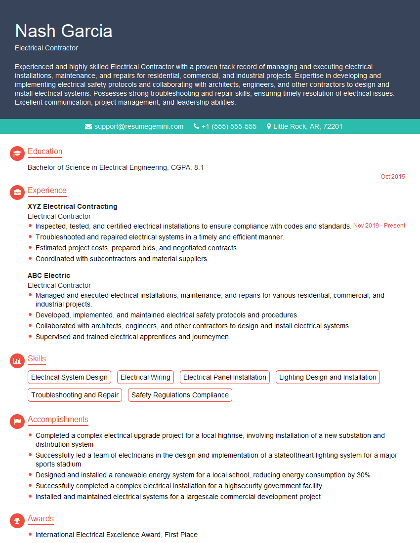
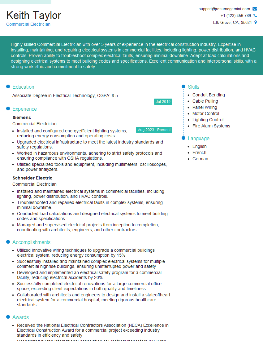
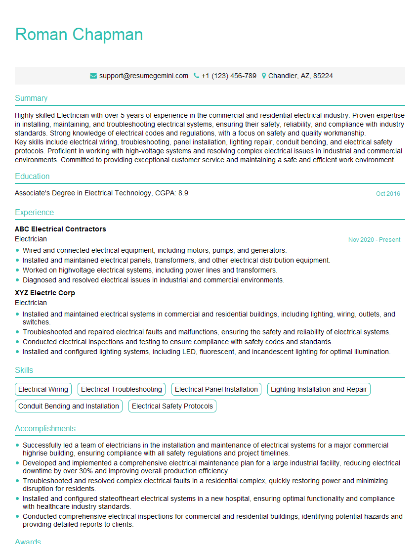
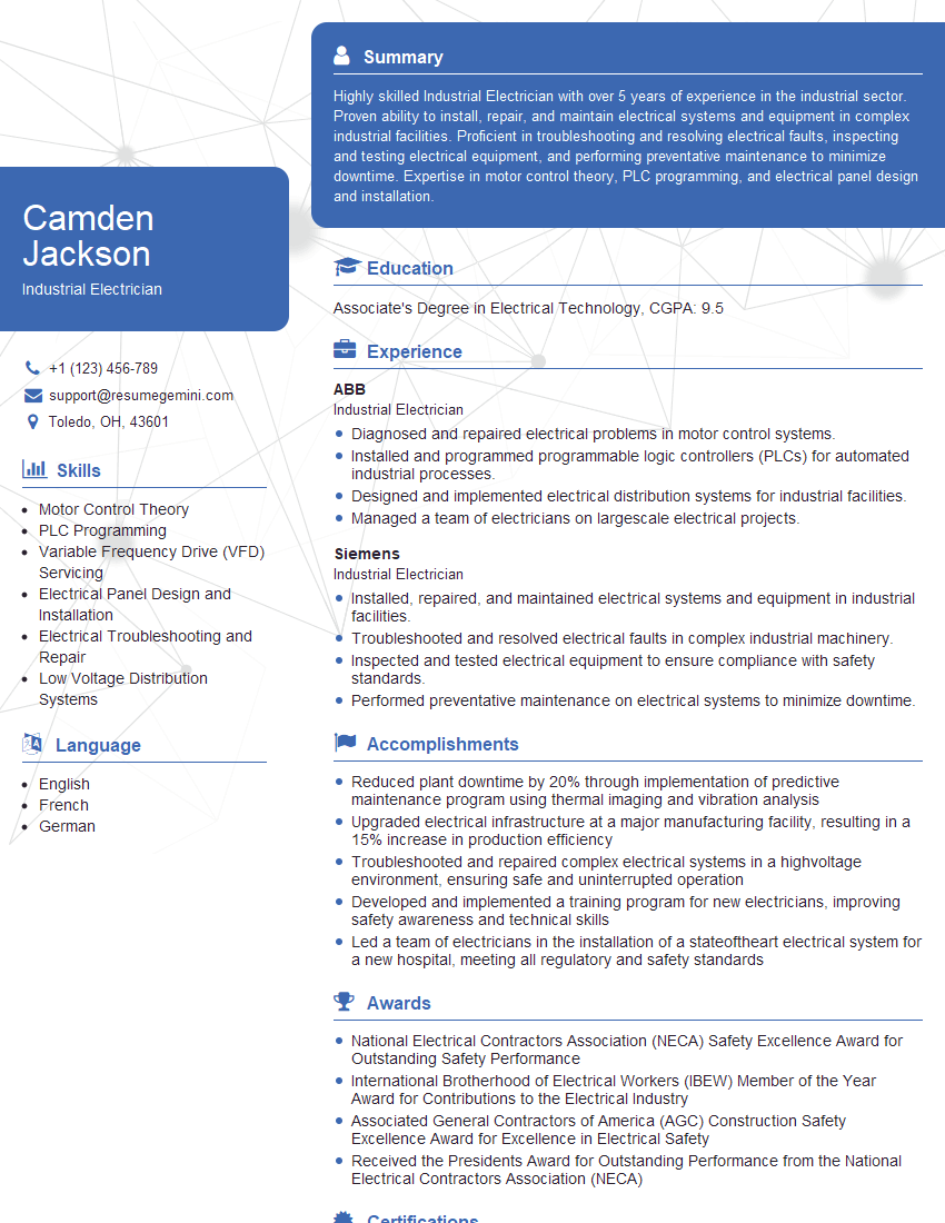
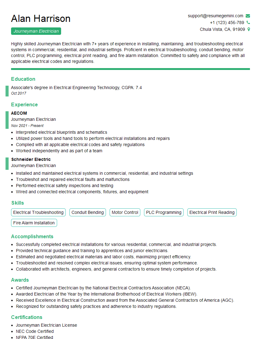
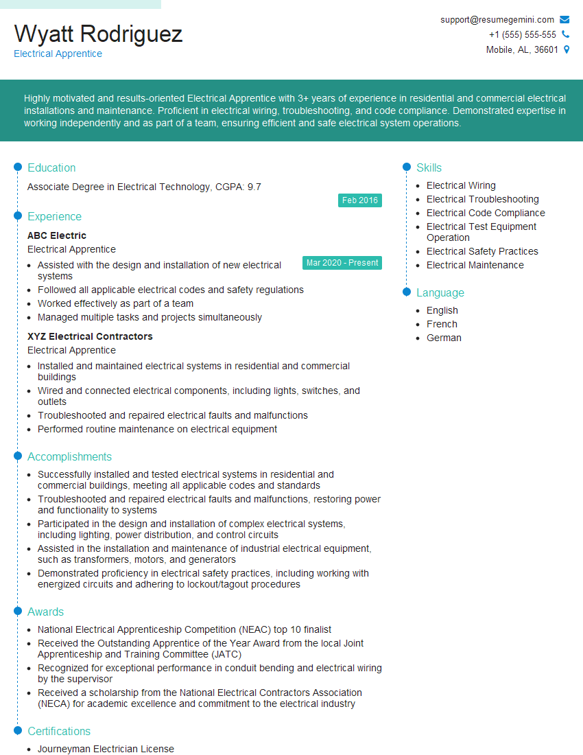
Mastering electrical systems installation and repair opens doors to diverse and rewarding career opportunities, offering excellent growth potential and competitive salaries. To maximize your job prospects, crafting a strong, ATS-friendly resume is crucial. ResumeGemini is a trusted resource that can help you build a professional resume that showcases your skills and experience effectively. Examples of resumes tailored to electrical systems installation and repair are available to help guide you. Take the next step towards your dream career – build your best resume today!
Explore more articles
Users Rating of Our Blogs
Share Your Experience
We value your feedback! Please rate our content and share your thoughts (optional).
What Readers Say About Our Blog
This was kind of a unique content I found around the specialized skills. Very helpful questions and good detailed answers.
Very Helpful blog, thank you Interviewgemini team.
