Preparation is the key to success in any interview. In this post, we’ll explore crucial Electrical Wiring and Controls interview questions and equip you with strategies to craft impactful answers. Whether you’re a beginner or a pro, these tips will elevate your preparation.
Questions Asked in Electrical Wiring and Controls Interview
Q 1. Explain the difference between AC and DC current.
The fundamental difference between AC (Alternating Current) and DC (Direct Current) lies in the direction of electron flow. In DC, electrons flow consistently in one direction, like water flowing down a river. This is the type of current produced by batteries. AC, on the other hand, is characterized by electrons that periodically change direction, oscillating back and forth like a pendulum. This cyclical change is usually sinusoidal. Household power is typically AC.
Think of it like this: DC is a constant stream, while AC is a wave. This difference impacts how we use electricity. DC is ideal for applications requiring a constant voltage, like charging your phone, while AC is better suited for transmission over long distances due to its ability to be easily stepped up and down in voltage using transformers.
Q 2. Describe the function of a circuit breaker.
A circuit breaker is a safety device designed to protect an electrical circuit from damage caused by overcurrent or short circuits. Essentially, it’s an automatic switch that interrupts the flow of electricity when it detects an unsafe level of current.
Imagine a circuit breaker as a fire sprinkler in your electrical system. If a fire (overcurrent) starts, the sprinkler (circuit breaker) activates, cutting off the water (electricity) to prevent further damage. Circuit breakers work by using a bimetallic strip or electromagnetic coil that heats up or deflects when excessive current flows. This triggers a mechanism that breaks the circuit, preventing overheating and potential fires. They are resettable, unlike fuses which need replacement after tripping.
Q 3. What are the different types of wiring methods?
There are several wiring methods, each with its own advantages and disadvantages depending on the application and environment. Some common methods include:
- Conduit Wiring: Wires are run inside protective metal or plastic pipes called conduits. This method offers excellent protection against physical damage and is often used in industrial settings or where durability is paramount. It’s also highly flexible, allowing for easy changes or additions later on.
- Surface Mount Wiring: Wires are attached directly to the surface of walls or ceilings using staples, clips, or molding. It’s a simpler and faster method, but offers less protection than conduit wiring. Commonly used in renovations or where conduit is impractical.
- Cable Tray Wiring: Wires are supported on trays that allow for easy access and maintenance, commonly used for larger wiring systems and industrial applications.
- Concealed Wiring: Wires are run inside walls or ceilings, providing a cleaner aesthetic but making repairs or modifications more challenging. It requires careful planning and adherence to local building codes.
The choice of wiring method depends on factors like cost, safety regulations, aesthetic requirements, accessibility for maintenance, and the specific application.
Q 4. Explain the purpose of grounding and bonding.
Grounding and bonding are critical safety measures in electrical systems that protect against electrical shocks and fires. Grounding connects a non-current-carrying metallic part of an electrical system to the earth, providing a low-resistance path for fault currents to flow. Bonding connects multiple metallic parts of an electrical system together, ensuring they are all at the same electrical potential.
Think of grounding as creating a safety valve. If a fault occurs, the excess current flows safely into the ground, preventing dangerous voltages from appearing on exposed metal parts. Bonding prevents voltage differences between conductive parts, eliminating the risk of shock should a fault develop.
In essence, grounding provides a path for fault currents to safely dissipate, while bonding ensures that metallic enclosures and parts are at the same potential, preventing dangerous voltage differences.
Q 5. How do you troubleshoot a faulty circuit?
Troubleshooting a faulty circuit requires a systematic approach. Here’s a step-by-step process:
- Safety First: Always disconnect the power before working on any electrical circuit.
- Visual Inspection: Carefully examine the circuit for any obvious problems like loose wires, damaged insulation, or burnt components.
- Test for Voltage: Use a voltage tester to check if power is reaching the circuit. This helps isolate whether the problem is upstream or within the circuit itself.
- Test for Continuity: Use a multimeter to check for continuity in the wiring to identify any breaks or open circuits.
- Check for Short Circuits: Use a multimeter to check for short circuits, which occur when wires touch unexpectedly, causing excessive current flow.
- Identify the Faulty Component: Once the problem area is identified, replace or repair the faulty component.
- Test the Circuit: After making repairs, retest the circuit to ensure it’s functioning correctly.
Documentation is key. Keep detailed records of your troubleshooting steps, measurements, and findings. This aids in quick resolution and future reference.
Q 6. What safety precautions do you take when working with electricity?
Safety is paramount when working with electricity. My safety practices always include:
- Lockout/Tagout Procedures: Always lock out and tag out the power source before working on any electrical equipment. This prevents accidental energization.
- Personal Protective Equipment (PPE): I consistently use appropriate PPE, including insulated gloves, safety glasses, and non-conductive footwear.
- Proper Tools: I only use properly insulated tools and equipment designed for electrical work.
- Awareness of Surroundings: I’m always aware of my surroundings and potential hazards, avoiding contact with water or other conductive materials.
- Following Codes and Regulations: I strictly adhere to all applicable electrical codes and regulations.
- Never Work Alone: I never work alone on electrical tasks; having a colleague for assistance and safety oversight.
I always approach electrical work with caution and respect for the potential dangers involved.
Q 7. Describe your experience with PLC programming.
I have extensive experience in PLC (Programmable Logic Controller) programming, primarily using Siemens TIA Portal and Rockwell Automation Studio 5000. I’ve worked on various projects involving process automation, machine control, and supervisory control and data acquisition (SCADA) systems. My expertise includes ladder logic programming, function block programming, and HMI (Human-Machine Interface) design.
For example, I recently programmed a PLC to control a complex packaging line, integrating sensors, actuators, and motor drives to ensure efficient and precise operation. This involved designing the ladder logic, implementing safety features, and developing an intuitive HMI for operators. I’m proficient in troubleshooting PLC programs and have experience with various communication protocols, such as Ethernet/IP and Profinet.
I’m comfortable working with both analog and digital I/O, and I’m familiar with various PLC programming techniques for optimizing efficiency and reliability. I’m always eager to learn new PLC programming technologies and approaches to enhance automation solutions.
Q 8. What is a ladder logic diagram and how is it used?
Ladder logic is a programming language used to design and implement control systems, particularly in industrial automation. Think of it as a visual representation of electrical circuits, resembling a ladder with rungs. Each rung represents a logical statement, and the entire diagram illustrates the flow of control signals.
On the left side of the ‘ladder’ are the inputs (sensors, switches, etc.), and on the right are the outputs (motors, lights, actuators, etc.). The rungs connect inputs to outputs through logical operations (AND, OR, NOT). If the logic on a rung is true, the output associated with that rung is energized; otherwise, it’s de-energized.
For example, imagine a simple system controlling a light. The input could be a pressure sensor. If the pressure is high (input is true), the light turns on (output is energized). This would be represented by a single rung connecting the pressure sensor to the light. More complex systems use combinations of inputs and multiple rungs to achieve intricate control scenarios.
Ladder logic is widely used because it’s intuitive and easy to understand, even for those without extensive programming experience. Its visual nature makes troubleshooting and modifications straightforward.
Q 9. Explain your experience with SCADA systems.
I have extensive experience with SCADA (Supervisory Control and Data Acquisition) systems, having worked with various platforms including Wonderware InTouch and Siemens WinCC. My responsibilities have included designing, implementing, and maintaining SCADA systems for a range of industrial applications, from water treatment plants to manufacturing facilities.
My experience encompasses all aspects of SCADA development, from database configuration and HMI (Human-Machine Interface) design to network setup and data communication. I’m proficient in configuring alarms, creating historical trends, and designing reports for real-time monitoring and data analysis. I’ve also been involved in integrating SCADA systems with other industrial control systems and enterprise resource planning (ERP) software.
In one project, I successfully implemented a SCADA system that reduced downtime by 15% in a manufacturing plant by providing real-time monitoring of critical equipment and allowing for proactive maintenance scheduling. This was achieved by integrating sensor data, PLC communications, and advanced alarming capabilities within the SCADA environment.
Q 10. How do you interpret electrical schematics?
Interpreting electrical schematics requires a systematic approach. I begin by understanding the purpose of the schematic – what system or component it represents. Then I systematically analyze the different symbols used. Each symbol represents a specific component, such as a motor, switch, resistor, capacitor, or PLC.
I follow the flow of signals and power through the diagram, tracing wires and noting connections. I pay close attention to component values (resistance, capacitance, voltage ratings) and identification markings. Understanding the different types of lines (e.g., solid lines for connections, dashed lines for control signals) is crucial. I often use a highlighter to trace specific circuits or paths within a complex schematic.
For example, I can identify the power supply, the control circuitry, and the load based on the symbols used. I can also determine how components are wired in series or parallel, and calculate the equivalent resistance or capacitance. Properly interpreting schematics is foundational for effective troubleshooting and design work.
Q 11. What are the different types of sensors used in control systems?
Control systems utilize a wide array of sensors to monitor and measure various parameters. They can be broadly categorized by the physical quantity they measure:
- Temperature Sensors: Thermocouples, RTDs (Resistance Temperature Detectors), thermistors. These are crucial for process control in applications like ovens, furnaces, and refrigeration systems.
- Pressure Sensors: Piezoresistive, capacitive, and strain gauge sensors. Used for monitoring pressure in pipelines, hydraulic systems, and pneumatic controls.
- Flow Sensors: Differential pressure, ultrasonic, and turbine flow meters. Essential for regulating fluid flow in chemical processes and pipelines.
- Level Sensors: Ultrasonic, capacitive, and float-type sensors. Used in tanks and reservoirs to monitor liquid or solid levels.
- Proximity Sensors: Inductive, capacitive, and photoelectric sensors. These detect the presence of objects without physical contact, useful for automated assembly lines and robotic applications.
- Position Sensors: Potentiometers, encoders, and LVDTs (Linear Variable Differential Transformers). Used to monitor the position of mechanical components in robotics and motion control systems.
The choice of sensor depends heavily on the application’s specific needs, including accuracy requirements, environmental conditions, and cost considerations.
Q 12. Explain your experience with motor control circuits.
My experience with motor control circuits is extensive. I’ve designed, implemented, and troubleshot circuits for various motor types, including AC induction motors, DC motors, and stepper motors. This includes working with both simple on/off control and more advanced techniques like variable frequency drives (VFDs) and programmable logic controllers (PLCs).
I am proficient in using various motor control methods, including:
- Direct On Line (DOL) starters: Simple but can cause high inrush currents.
- Star-Delta starters: Reduce inrush current compared to DOL starters.
- Soft starters: Gradually increase motor voltage, reducing mechanical stress.
- Variable Frequency Drives (VFDs): Provide precise control over motor speed and torque.
I have experience selecting appropriate motor protection devices like overload relays and thermal protectors to prevent motor damage. For example, in a recent project, I designed a motor control system using a VFD to optimize the speed of a conveyor belt, leading to a significant increase in production efficiency and energy savings. This involved detailed calculations, selecting suitable components, and ensuring the safety of the system.
Q 13. Describe your troubleshooting skills related to control systems.
My troubleshooting approach to control systems is systematic and methodical. I begin by gathering information: reviewing error messages, observing the system’s behavior, and interviewing operators to understand the problem’s nature and history.
Next, I use a combination of techniques:
- Visual Inspection: Checking for loose wires, damaged components, and obvious signs of malfunction.
- Instrumentation: Using multimeters, oscilloscopes, and other instruments to measure voltages, currents, and signals at various points in the circuit.
- Ladder Logic/Program Review: Examining the control program for logic errors, incorrect settings, or missing components.
- Signal Tracing: Following the signal path to identify points of failure or unexpected behavior.
I document each step of my troubleshooting process, including observations, measurements, and corrective actions. This systematic approach helps ensure accurate diagnosis and efficient repair, minimizing downtime and improving system reliability. For instance, I once quickly identified a faulty sensor in a complex manufacturing process by using a combination of visual inspection and signal tracing, preventing a significant production delay.
Q 14. What is your experience with industrial communication protocols (e.g., Profibus, Ethernet/IP)?
I have significant experience with industrial communication protocols, including Profibus, Ethernet/IP, Modbus, and Profinet. My experience spans their application in various industrial control environments, from simple point-to-point connections to complex networks involving multiple PLCs, sensors, actuators, and human-machine interfaces.
I understand the intricacies of each protocol, including their physical layers, data structures, and communication methods. I’m capable of configuring network devices, troubleshooting communication problems, and selecting appropriate protocols based on project requirements. For example, I have successfully integrated multiple PLCs from different manufacturers using Ethernet/IP, enabling seamless data exchange and coordinated control.
My understanding extends to the security aspects of these protocols, ensuring that systems are protected against unauthorized access and cyber threats. I’m familiar with the relevant industry standards and best practices for secure industrial communication networks.
Q 15. How do you ensure compliance with electrical codes and standards?
Ensuring compliance with electrical codes and standards is paramount for safety and legal reasons. It’s not just about following rules; it’s about protecting lives and property. My approach involves a multi-step process. First, I meticulously review the relevant codes, such as the National Electrical Code (NEC) in the US, or equivalent standards in other regions. This includes understanding the specific requirements for the project, considering factors like the environment, load calculations, and the type of installation. Second, I develop detailed design plans that explicitly address each code requirement. These plans include accurate calculations, detailed diagrams, and material specifications, all clearly documented. Third, during the installation phase, I maintain rigorous quality control. This involves regular inspections to ensure adherence to the design and code compliance at each stage. Finally, all work is documented comprehensively, including inspection reports and test results, to provide a complete audit trail. A real-world example is a recent project where we had to comply with strict grounding requirements in a hazardous location. By meticulously following the NEC’s Article 500 guidelines, we ensured the safety of personnel and equipment.
Career Expert Tips:
- Ace those interviews! Prepare effectively by reviewing the Top 50 Most Common Interview Questions on ResumeGemini.
- Navigate your job search with confidence! Explore a wide range of Career Tips on ResumeGemini. Learn about common challenges and recommendations to overcome them.
- Craft the perfect resume! Master the Art of Resume Writing with ResumeGemini’s guide. Showcase your unique qualifications and achievements effectively.
- Don’t miss out on holiday savings! Build your dream resume with ResumeGemini’s ATS optimized templates.
Q 16. Explain your experience with different types of relays.
Relays are the workhorses of many control systems, acting as electrically operated switches. My experience encompasses various types, each suited for different applications. I’ve extensively worked with electromechanical relays, which use an electromagnet to actuate mechanical contacts. These are robust and reliable but can be slower than other types. Solid-state relays (SSRs), which use semiconductor devices to switch circuits, offer faster switching speeds and longer lifespans, ideal for high-frequency applications. I’ve also utilized time-delay relays, which introduce a time delay before switching, useful in sequencing operations. For instance, in a motor starter circuit, a time-delay relay might provide a controlled ramp-up to prevent excessive inrush current. Finally, I’m proficient with thermal relays, employed for motor protection, which trip when an overload or overheating condition is detected. Each relay type presents its own advantages and disadvantages, and choosing the right one depends on the specific application requirements. For example, In one project, we used SSRs to control high-speed lighting systems requiring rapid switching, while in another, electromechanical relays were chosen for their simplicity and reliability in a harsh industrial setting.
Q 17. Describe your experience with Programmable Logic Controllers (PLCs).
Programmable Logic Controllers (PLCs) are the brains of modern automation systems. My experience involves programming PLCs using various programming languages like Ladder Logic (LD), Function Block Diagram (FBD), and Structured Text (ST). I’m comfortable with different PLC platforms from manufacturers like Allen-Bradley, Siemens, and Schneider Electric. I can design and implement complex control systems, including sequence control, data acquisition, and communication with other devices using various communication protocols like Modbus, Ethernet/IP, and Profibus. For example, I recently worked on a project where we used a PLC to automate a packaging line, controlling conveyors, sensors, and robotic arms to optimize throughput and minimize downtime. The PLC’s programmability allowed for flexible adjustments to production parameters and real-time monitoring of the entire process. Another project involved creating a supervisory control and data acquisition (SCADA) system using a PLC to remotely monitor and control a water treatment plant.
Q 18. What are the different types of control loops?
Control loops are fundamental to process automation. They maintain a desired process variable at a setpoint by continuously monitoring and adjusting the manipulated variable. Common types include:
- Feedback Control Loops: These loops use the measured output of the process to adjust the input. A classic example is a thermostat controlling room temperature.
- Feedforward Control Loops: These loops anticipate changes in the process based on predicted disturbances, rather than relying solely on feedback. For example, predicting and compensating for changes in ambient temperature affecting a chemical reaction.
- Cascade Control Loops: These employ multiple control loops, where the output of one loop serves as the setpoint for another. This improves control accuracy and performance; a common example is a temperature control system with an inner loop controlling a heater’s power and an outer loop maintaining the overall temperature.
- Ratio Control Loops: These maintain a constant ratio between two process variables. For instance, controlling the fuel-to-air ratio in a combustion process.
Q 19. Explain the concept of PID control.
PID control is a widely used feedback control algorithm that adjusts the manipulated variable based on three terms: Proportional, Integral, and Derivative.
- Proportional (P): This term is proportional to the error (difference between setpoint and measured value). A larger error results in a larger correction.
- Integral (I): This term accounts for accumulated error over time. It eliminates steady-state error, ensuring the process eventually reaches the setpoint.
- Derivative (D): This term anticipates future error based on the rate of change of the error. It helps to damp oscillations and improve response time.
Q 20. How do you handle emergency situations related to electrical equipment?
Handling electrical emergencies requires swift, decisive action, prioritizing safety. My first step is to de-energize the affected equipment immediately by isolating the power source using appropriate lockout/tagout procedures. This prevents further hazards and protects personnel. Next, I assess the situation to determine the nature and extent of the problem. This might involve inspecting for visible damage, checking for arc flashes, or using specialized equipment to diagnose the fault. Based on my assessment, I call for emergency services if necessary, ensuring the affected area is secured and personnel are evacuated if required. After the immediate danger is mitigated, I conduct a thorough investigation to determine the root cause of the incident and implement preventive measures to avoid similar occurrences in the future. Proper documentation of the incident, including corrective actions taken, is crucial for safety compliance. In one instance, a short circuit caused a small fire. I immediately de-energized the system, extinguished the fire with a fire extinguisher, and then called the fire department for a full inspection.
Q 21. What are your experiences with various types of electrical motors?
My experience encompasses a range of electrical motors, including:
- Induction Motors: These are widely used for their robustness and simplicity, particularly in industrial applications. I’m proficient in selecting appropriate induction motor sizes and types based on load requirements and operating conditions.
- Synchronous Motors: I have experience with synchronous motors for applications requiring precise speed control or power factor correction. These are often used in high-precision machinery or power generation.
- DC Motors: I have worked with various DC motors, including brushed and brushless types. These are suitable for applications requiring variable speed control, often seen in robotics and automation.
- Stepper Motors: I’ve used stepper motors for precise positioning applications, particularly in CNC machines and automated assembly lines.
- Servo Motors: These motors provide high-precision speed and position control, often used in robotics and motion control systems.
Q 22. Explain the differences between various types of transformers.
Transformers are essential components in electrical systems, primarily used to change the voltage level of alternating current (AC). They work based on the principle of electromagnetic induction. Several types exist, each suited for different applications. Key differences lie in their core construction, winding configuration, and operational characteristics.
- Step-up Transformers: These increase the voltage. Imagine a water pump increasing water pressure – the voltage is analogous to pressure. A common example is the transformer at a substation stepping up voltage for long-distance transmission.
- Step-down Transformers: These decrease the voltage. Think of a pressure regulator reducing water pressure to a safer level for household use. These are essential for bringing high-voltage transmission lines down to safer levels for homes and businesses.
- Isolation Transformers: These don’t change the voltage significantly but provide electrical isolation between the input and output circuits. This is crucial for safety reasons, preventing ground faults from affecting other parts of the system. Think of it as a protective barrier.
- Autotransformers: These have only one winding, with a portion tapped to change the voltage. They are smaller and cheaper than two-winding transformers but lack the isolation provided by isolation transformers. They are often used in applications where a small voltage adjustment is needed.
- Power Transformers: These are large transformers designed for high power applications like power grids. They need robust construction and effective cooling mechanisms to handle the high currents and heat generated.
- Instrument Transformers: These are used for measuring purposes such as current and voltage. Current transformers reduce high currents to safer levels for measuring instruments, and voltage transformers step down high voltages.
The core material (e.g., iron, ferrite) significantly affects efficiency and performance. Different core types are chosen based on the frequency and power level of the application.
Q 23. What is your experience with power distribution systems?
My experience with power distribution systems spans over [Number] years, encompassing various aspects from design and implementation to troubleshooting and maintenance. I’ve worked on projects ranging from small commercial buildings to larger industrial facilities. This includes hands-on experience with:
- Substation design and operation: I’ve been involved in the design and commissioning of substations, including selecting appropriate transformers, switchgear, and protection relays. This required a thorough understanding of power flow analysis and system protection schemes.
- Overhead and underground distribution: I’m proficient in both overhead and underground distribution systems, including cable sizing, fault location, and preventative maintenance. I’ve worked with various cable types and understand the importance of proper grounding.
- Protection and control systems: I’ve extensively worked with various protective relays, circuit breakers, and SCADA (Supervisory Control and Data Acquisition) systems. Understanding the logic behind these systems is critical for safe and reliable operation. For example, I once helped troubleshoot a faulty protective relay causing unnecessary tripping on a major distribution line by systematically checking the settings and identifying the misconfiguration.
- Power quality analysis: I’ve analyzed power quality issues such as harmonics, voltage sags, and surges, using specialized equipment and software to identify and mitigate these problems.
I also have experience with the use of sophisticated software for power system simulation and analysis, enabling me to model and predict system behavior under different operating conditions.
Q 24. Describe your proficiency with electrical testing equipment.
My proficiency with electrical testing equipment is extensive. I’m comfortable using a wide range of instruments, including:
- Multimeters: For measuring voltage, current, resistance, and continuity. Knowing how to use a multimeter safely and accurately is fundamental to any electrical work.
- Clamp meters: For measuring current without breaking the circuit. These are invaluable for safely measuring high currents in live circuits.
- Megohmmeters (Meggers): To test insulation resistance. This is crucial for preventative maintenance and ensuring the safety of electrical equipment. A low insulation resistance can indicate a potential fault.
- Digital insulation testers: For precise measurement of insulation resistance and dielectric strength. These provide more detailed information than traditional Meggers.
- Power quality analyzers: For measuring various aspects of power quality, including harmonics, voltage fluctuations, and power factor. Identifying power quality issues is crucial for the reliable operation of electrical equipment.
- Loop testers: To test the effectiveness of earth fault protection in a circuit. Ensuring earth fault protection is functioning correctly is critical for electrical safety.
Beyond the technical skills of using these tools, I emphasize safe operating procedures and adherence to relevant safety standards when utilizing these devices.
Q 25. What are your experiences with different types of wiring diagrams?
I’m experienced with various types of wiring diagrams, each serving a unique purpose:
- Schematic Diagrams: These show the components and their connections using standardized symbols. They’re excellent for understanding the overall system functionality but don’t usually show the physical layout.
- Wiring Diagrams: These depict the actual physical connections between components. They’re essential for installation and troubleshooting. There are different types such as ladder diagrams and single-line diagrams.
- One-line Diagrams: These simplified representations show the major components and connections of a power system. They are commonly used in power system analysis and planning.
- Ladder Diagrams: Frequently used in industrial control systems (PLCs), they use a ladder-like format to represent the logic of control circuits. They’re very helpful for troubleshooting programmable logic controllers (PLCs).
My experience extends to interpreting and creating these diagrams using both hand-drawn methods and various electrical CAD software.
For instance, I recently used a ladder diagram to troubleshoot a malfunctioning conveyor belt control system in a factory. By carefully tracing the logic flow in the diagram, I quickly identified a faulty relay that was causing the problem. This demonstrates the practical importance of understanding various diagram types.
Q 26. How familiar are you with NEC (National Electrical Code) or other relevant standards?
I’m very familiar with the NEC (National Electrical Code) and other relevant international standards such as IEC (International Electrotechnical Commission) standards. I understand the importance of adhering to these codes to ensure safety and compliance. My knowledge includes:
- Wiring methods and installation practices: I’m well-versed in the various methods for wiring, cable sizing, and conduit installation, all in accordance with NEC requirements.
- Grounding and bonding requirements: I understand the importance of proper grounding and bonding for safety and to prevent electrical shocks and equipment damage.
- Overcurrent protection: I know how to select and install appropriate overcurrent protection devices, such as circuit breakers and fuses, to protect circuits and equipment.
- Arc flash hazard analysis: I understand the risks associated with arc flash incidents and how to mitigate these risks by implementing appropriate safety measures.
Regularly reviewing updates to the NEC and other standards is an important part of my professional development, ensuring that I maintain my knowledge and expertise in the latest safety and installation best practices. This ensures my work remains compliant and safe.
Q 27. Describe a complex electrical problem you solved. What was your approach?
One challenging problem I encountered involved intermittent power outages in a large manufacturing plant. Initially, the problem seemed random, affecting different parts of the facility at different times. My approach was systematic and involved the following steps:
- Data collection: I started by gathering data on the frequency, duration, and location of the outages. This involved reviewing maintenance logs and interviewing plant personnel.
- Visual inspection: I conducted a thorough visual inspection of the electrical system, looking for any obvious signs of damage or wear. This included checking connections, insulation, and equipment.
- Testing and diagnostics: I used various testing equipment, including multimeters, clamp meters, and a power quality analyzer, to systematically check the different components of the system. This highlighted voltage fluctuations on one particular feeder.
- Troubleshooting: Based on the data and testing results, I narrowed down the problem to a faulty underground cable. Using a cable fault locator, I pinpointed the location of the damage, which was a significant break in the insulation.
- Solution implementation: The damaged section of cable was excavated and repaired, resolving the intermittent power outages. I also recommended preventative measures, including regular cable testing, to prevent future occurrences.
The key to solving this problem was a methodical approach, combining data analysis, hands-on testing, and careful interpretation of the results. It emphasized the importance of preventative maintenance and rigorous testing procedures.
Q 28. Explain your understanding of electrical safety regulations.
Electrical safety regulations are paramount in my work. My understanding encompasses various aspects, including:
- Lockout/Tagout procedures: I’m proficient in using lockout/tagout procedures to de-energize equipment before maintenance or repair work. This is a critical safety measure to prevent accidental energization.
- Personal protective equipment (PPE): I always use appropriate PPE, including insulated gloves, safety glasses, and arc flash suits when working on electrical systems. The level of PPE is chosen based on the risk assessment.
- Working at heights safety: If working at heights is involved, I ensure that proper fall protection measures are in place.
- Confined space entry procedures: If working in confined spaces, I follow strict confined space entry procedures.
- Emergency response: I am trained in emergency response procedures, including CPR and first aid.
Beyond the specific regulations, I hold a strong commitment to a safety-first mindset. I believe that safety is not just a set of rules, but a culture that should be fostered in every workplace. Regular safety training and a proactive approach to identifying and mitigating hazards are vital. This proactive approach prevents accidents and contributes to a safer working environment for everyone.
Key Topics to Learn for Electrical Wiring and Controls Interview
- Electrical Codes and Standards: Understanding NEC (National Electrical Code) and other relevant standards is crucial for safe and compliant installations. Be prepared to discuss specific code articles and their practical implications.
- Wiring Diagrams and Schematics: Practice interpreting and creating various types of wiring diagrams, including single-line, ladder, and schematic diagrams. Be ready to explain the logic behind different symbols and components.
- Wiring Methods and Techniques: Demonstrate knowledge of different wiring methods (e.g., conduit bending, cable termination, splicing techniques) and their applications in various environments (industrial, commercial, residential).
- Electrical Components and Devices: Familiarize yourself with the operation and application of various electrical components such as switches, relays, circuit breakers, contactors, motors, and sensors. Understand their selection criteria and troubleshooting techniques.
- Control Systems and Automation: Gain a solid understanding of programmable logic controllers (PLCs), human-machine interfaces (HMIs), and other control systems used in industrial automation. Be prepared to discuss their programming and troubleshooting.
- Troubleshooting and Diagnostics: Develop your skills in identifying and resolving electrical faults using various testing equipment (multimeters, clamp meters, etc.). Practice describing your methodical troubleshooting approach.
- Safety Procedures and Practices: Highlight your understanding of lockout/tagout procedures, personal protective equipment (PPE), and other safety protocols crucial for working with electrical systems.
- Motor Control Circuits: Understand different motor control methods (e.g., direct-on-line starting, reduced voltage starting, variable frequency drives (VFDs)) and their applications. Be able to discuss the advantages and disadvantages of each.
Next Steps
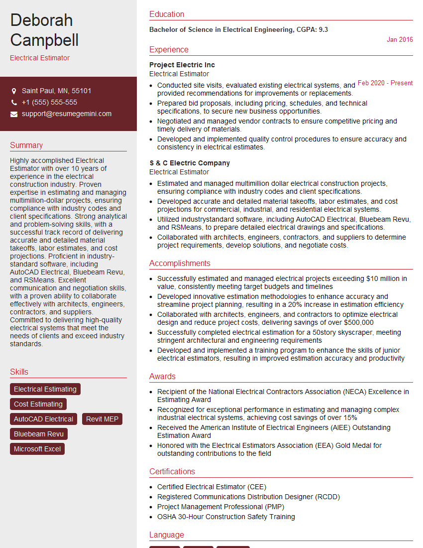
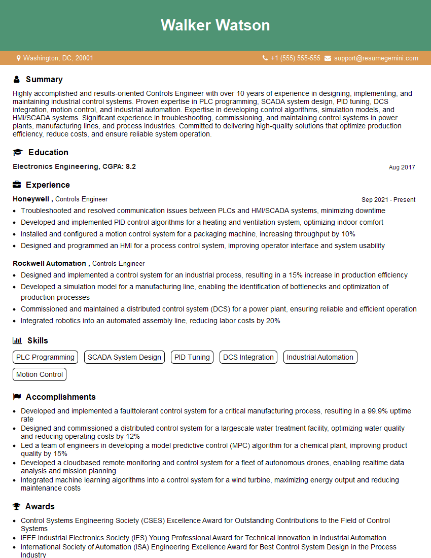
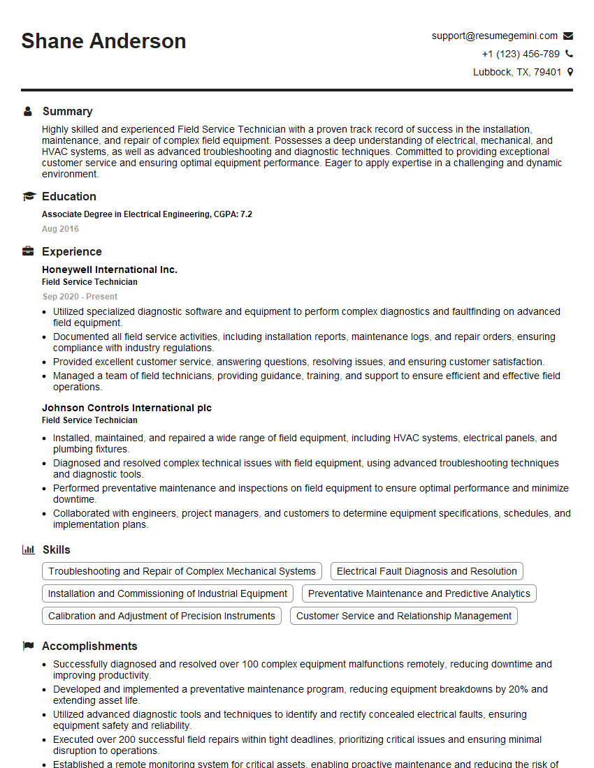
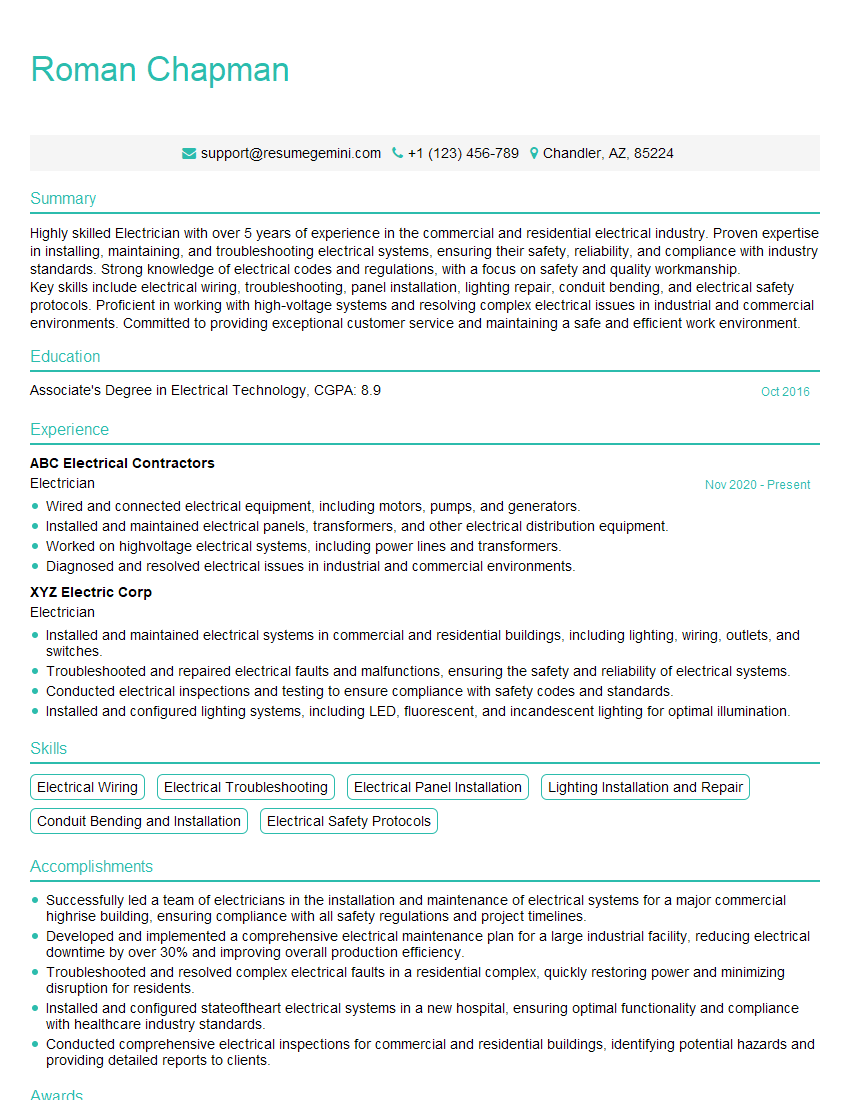
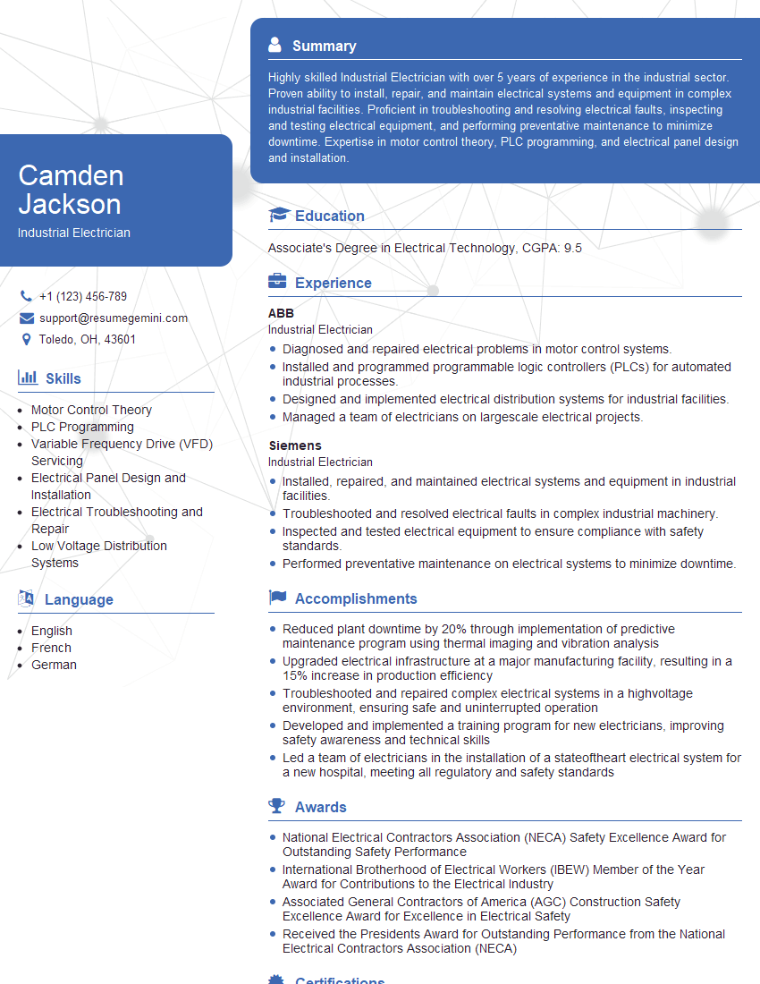
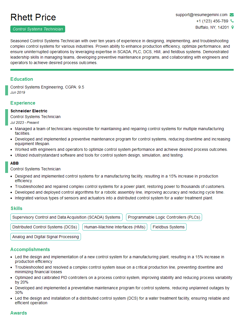
Mastering Electrical Wiring and Controls opens doors to a wide range of exciting and rewarding career opportunities in various industries. To significantly increase your chances of landing your dream job, it’s vital to present yourself with a strong, ATS-friendly resume that highlights your skills and experience effectively. ResumeGemini is a trusted resource that can help you create a professional and impactful resume tailored to the specific requirements of your target roles. We provide examples of resumes specifically designed for Electrical Wiring and Controls professionals to help you get started. Invest in crafting a compelling resume – it’s your first impression and a key step towards a successful career.
Explore more articles
Users Rating of Our Blogs
Share Your Experience
We value your feedback! Please rate our content and share your thoughts (optional).
What Readers Say About Our Blog
This was kind of a unique content I found around the specialized skills. Very helpful questions and good detailed answers.
Very Helpful blog, thank you Interviewgemini team.
