Interviews are more than just a Q&A session—they’re a chance to prove your worth. This blog dives into essential Engineering Drawing Standards interview questions and expert tips to help you align your answers with what hiring managers are looking for. Start preparing to shine!
Questions Asked in Engineering Drawing Standards Interview
Q 1. Explain the purpose and importance of engineering drawing standards.
Engineering drawing standards are a set of rules and conventions that ensure clarity, consistency, and accuracy in technical drawings. They act as a universal language for engineers, designers, and manufacturers worldwide. Without standards, interpreting a drawing could be ambiguous and lead to costly mistakes in manufacturing or construction. Think of it like a recipe – a well-defined recipe (standard) ensures everyone bakes the same cake (product). The importance lies in facilitating effective communication, minimizing errors, ensuring interchangeability of parts, and simplifying global collaboration on projects.
- Improved Communication: Standards guarantee that everyone understands the drawing in the same way, regardless of their location or background.
- Reduced Errors: Standardized symbols, notations, and procedures reduce the risk of misinterpretations and errors during design, manufacturing, and construction.
- Enhanced Efficiency: Standardized processes streamline workflows and improve overall efficiency in the design and manufacturing process.
- Global Collaboration: Standards allow engineers across different countries and organizations to work collaboratively on projects with ease.
Q 2. Describe different types of lines used in engineering drawings and their significance.
Engineering drawings utilize various line types to convey different information. Each line type has a specific weight and style to differentiate its meaning. Let’s look at some common ones:
- Visible Outline: A thick, solid line indicating visible edges of an object. Imagine tracing the outline of a cup – that’s your visible outline.
- Hidden Outline: A thin, dashed line representing edges not directly visible but inferred. Think of drawing the inside of a box you can only see the outside of.
- Center Line: A thin, alternating long and short dash line defining axes of symmetry or centers of holes. This is like drawing a line down the middle of a perfectly symmetrical object.
- Section Line: Thin, evenly spaced lines used to indicate a cut through an object. This helps you visually understand the internal structure.
- Dimension Line: Thin lines terminated with arrowheads used to indicate distances. They are essential for providing measurements in the drawing.
- Extension Line: Thin lines extending from the object to the dimension line. These guide the dimension line to the correct place.
- Break Line: A series of short dashes with a zig-zag pattern used to shorten long, uniform features on a drawing, saving space.
The significance is clear distinction. A misplaced or incorrectly drawn line can completely change the interpretation of the drawing. Adherence to line standards prevents errors and ensures accuracy.
Q 3. What are the standard sheet sizes used in engineering drawings?
Standard sheet sizes for engineering drawings are based on ISO (International Organization for Standardization) standards, often derived from A-size series. The most common are:
- A0: The largest size, roughly 841 mm x 1189 mm
- A1: Half the area of A0, 594 mm x 841 mm
- A2: Half the area of A1, 420 mm x 594 mm
- A3: Half the area of A2, 297 mm x 420 mm
- A4: Half the area of A3, 210 mm x 297 mm (standard printer paper size)
These sizes are chosen for their convenient aspect ratio (approximately 1:1.414) and scalability. Folding an A-size sheet in half results in another A-size sheet. This is extremely useful for creating sets of drawings.
Q 4. Explain the difference between orthographic and isometric projections.
Both orthographic and isometric projections are methods for representing three-dimensional objects on a two-dimensional surface, but they differ significantly in their perspective:
- Orthographic Projection: Uses multiple views (typically front, top, and side) to show the object from different angles. Each view shows only two dimensions. Imagine looking at different sides of a box separately. This method provides complete geometric information but can be challenging to visualize the object as a whole.
- Isometric Projection: Uses a single view that shows all three dimensions at once, providing a three-quarter perspective. While offering a better visual representation of the object, some distortions in angles and dimensions might occur. It’s like a slightly skewed photograph of the object.
In practice, orthographic projections are primarily used for detailed design and manufacturing, while isometric projections are more frequently utilized for conceptual design, presentations, and illustrations.
Q 5. How do you create a section view in an engineering drawing?
A section view in an engineering drawing reveals the internal features of an object by imagining a ‘cut’ through it. Here’s how you create one:
- Identify the Cutting Plane: Determine where you want to ‘cut’ the object to reveal its interior. This is indicated on the drawing with a cutting plane line (usually a thick, dashed line).
- Indicate the Section View: Draw a section view, depicting what is visible when the object is cut along the cutting plane. Use section lines (thin, parallel lines) to represent the cut surface. The spacing and orientation of section lines are usually standardized.
- Label the Section View: Clearly label the section view to indicate the location of the cut using a letter or number referencing the cutting plane line.
Section views are invaluable for showing internal features such as holes, ribs, or complex shapes that would otherwise be hidden in a standard view. For example, to show the internal threads of a bolt, a section view is essential.
Q 6. What are the different types of dimensioning techniques?
Different dimensioning techniques are employed to clearly and accurately communicate the sizes and locations of features on an engineering drawing. Some common types include:
- Aligned Dimensioning: Dimension lines are aligned parallel to the feature being measured.
- Unidirectional Dimensioning: All dimension figures are oriented in the same direction, typically horizontally.
- Chain Dimensioning: Dimensions are placed consecutively along a line.
- Coordinate Dimensioning: Locations are defined by coordinates relative to a datum point.
- Radial Dimensioning: Dimensions are measured from the center of a circle or arc.
- Angular Dimensioning: Dimensions indicate angles.
The choice of technique depends on the complexity of the part and the clarity it provides. Improper dimensioning can lead to manufacturing errors.
Q 7. What are the rules for applying tolerances in engineering drawings?
Tolerances in engineering drawings specify the permissible variations in dimensions or form. They’re crucial because manufacturing processes can’t achieve perfect precision. Tolerances define acceptable deviations from the nominal (intended) size. They are usually expressed using a plus/minus (±) notation or limits (e.g., 10 ± 0.1 mm, or 10.000 – 10.100 mm).
Rules for applying tolerances:
- Clear Indication: Tolerances must be clearly indicated next to the corresponding dimension. Generic tolerance values shouldn’t be assumed.
- Appropriate Selection: The chosen tolerance depends on the function of the part and the manufacturing process. A tight tolerance is usually more expensive to achieve.
- Geometric Dimensioning and Tolerancing (GD&T): For complex parts, GD&T symbols are used to specify tolerances on form, orientation, location, and runout, offering a more robust and precise definition of acceptable variation.
- Consistency: Consistent application of tolerance values across the drawing is essential for clarity.
Incorrect tolerances can result in parts that don’t fit together properly, compromising functionality and performance. Mastering tolerance application is crucial for successful engineering design and manufacturing.
Q 8. How do you represent materials in an engineering drawing?
Representing materials in engineering drawings is crucial for ensuring the correct manufacturing and assembly of a product. We typically use material designations, often adhering to standards like ISO or ASME. This ensures everyone understands what material is intended.
- Material Symbols: Simple symbols, often coupled with a text label, indicate the material. For example, a circle with a cross might indicate steel, while a filled triangle might indicate aluminum. However, reliance on symbols alone is discouraged due to potential ambiguity.
- Material Specifications: The most precise method is to use a material specification, such as a grade of steel (e.g., ASTM A36) or an aluminum alloy designation (e.g., 6061-T6). This eliminates any guesswork.
- Material Notes and Callouts: A detailed parts list or a materials list in the drawing’s title block or accompanying documentation is standard practice. This allows for clarifying specific requirements beyond simple symbols.
Example: Instead of just drawing a symbol, you’d specify “Material: ASTM A36 Steel” directly on the drawing next to the part or within a parts list. This leaves no room for misinterpretation.
Q 9. Explain the significance of title blocks and revision tables.
Title blocks and revision tables are fundamental components of any professional engineering drawing, ensuring clear communication and traceability. Think of them as the drawing’s passport and history.
- Title Block: This is a standardized block typically located in the lower right-hand corner (although this can vary by standard). It contains crucial information such as drawing number, title, revision number, date, scale, designer’s name, company name, client name, and sheet number (in multi-sheet drawings). It acts as a summary of the drawing’s purpose and metadata.
- Revision Table: This table records all changes made to a drawing after its initial release. Each entry notes the revision number, date of revision, description of the change, and the initials of the person who authorized the change. This is crucial for maintaining consistent and accurate records, particularly when drawings undergo numerous iterations.
Significance: These elements ensure that everyone working with the drawing has the correct and most up-to-date information, reducing errors and ambiguity during manufacturing and assembly. Imagine a construction project where blueprints were lacking accurate revision information; disaster could strike!
Q 10. What are the common symbols used in engineering drawings and their meanings?
Engineering drawings employ a variety of standardized symbols to convey information concisely. These symbols are universally recognized within the engineering community and are defined by relevant standards (like ANSI or ISO).
- Surface Finish Symbols: These symbols indicate the required surface finish of a part, specifying roughness, waviness, etc. For example, a symbol with various types of lines indicates different surface finish classes.
- Welding Symbols: These symbols provide detailed information about weld types, location, size, and other properties. They often show a reference line with details on the type of weld, weld size, and location on the parts.
- Dimensioning and Tolerancing Symbols: These symbols dictate the precision and acceptable variations in dimensions. GD&T (Geometric Dimensioning and Tolerancing) symbols, for instance, specify tolerances beyond simple plus/minus values, ensuring proper part fit and function.
- Section Views: Symbols indicating section cuts show the internal structure of an object by cutting through it. The orientation and type of cut are clearly indicated.
Example: A circle with a wavy line inside often signifies a surface roughness requirement. The meaning of these symbols is extensively documented in relevant standards, avoiding misunderstandings.
Q 11. Describe the process of creating a detailed assembly drawing.
Creating a detailed assembly drawing involves a systematic process of combining individual part drawings to show how components fit together to form a complete assembly.
- Gathering Part Drawings: Begin by ensuring all individual part drawings are complete, accurate, and appropriately dimensioned and toleranced.
- Assembly Planning: Determine the assembly sequence—the order in which parts are joined. This influences how you arrange components in the drawing.
- Layout and Positioning: Position the parts in a clear and understandable arrangement within the drawing space, using appropriate views (isometric, orthographic, etc.).
- Adding Assembly Details: Show the relationship between parts using annotations, callouts, fasteners, and exploded views (where appropriate) to illustrate how parts interact.
- Adding Bill of Materials (BOM): A BOM is essential. This is a table listing each part, its quantity, material, and part number—necessary for manufacturing.
- Dimensioning and Tolerancing: Add overall dimensions of the assembly, as well as key dimensions defining the assembly’s functionality. Note any critical clearances or alignment requirements.
- Review and Revision: Carefully review the drawing for clarity and accuracy, and check against the assembly plan. Iterate until the drawing accurately and clearly represents the assembled product.
Real-World Example: Creating assembly drawings for a complex engine, where each piston, connecting rod, and cylinder must be precisely shown in their relative positions, requires meticulous planning and attention to detail.
Q 12. How do you create detailed drawings from 3D models?
Generating detailed drawings from 3D models is a cornerstone of modern engineering design. CAD software significantly streamlines this process. The general process involves using the 3D model as a foundation from which to generate 2D views.
- Model Preparation: Ensure the 3D model is complete, accurate, and properly constrained before proceeding. Check for any errors or inconsistencies in the geometry.
- View Selection: Choose appropriate views (front, top, side, isometric, sections) to fully capture all necessary details. The selection depends on the complexity of the model and the information needed for manufacturing.
- Projection and Generation: Utilize the CAD software’s tools to generate 2D projections (orthographic views) and sections from the 3D model. The software automatically creates dimensions and annotations based on the 3D model data.
- Dimensioning and Annotation: Review and adjust automatically generated dimensions and annotations. Add any required dimensions, tolerances, notes, and material specifications not automatically included.
- Review and Revision: Carefully review the final 2D drawings to ensure accuracy, clarity, and completeness. Compare them to the 3D model to validate the drawing’s correctness.
Software tools: Software like AutoCAD, SolidWorks, Creo, and Inventor offer extensive capabilities for creating 2D drawings from 3D models. They automate many of these steps, enhancing efficiency.
Q 13. What are the benefits of using CAD software for engineering drawings?
CAD (Computer-Aided Design) software offers numerous advantages in creating and managing engineering drawings.
- Increased Accuracy: CAD software minimizes manual drafting errors, leading to more precise and reliable drawings.
- Enhanced Efficiency: Automation capabilities significantly reduce drafting time, allowing engineers to focus on design innovation rather than tedious manual work.
- Improved Collaboration: CAD software facilitates collaboration among engineers through version control and shared access to designs.
- Better Visualization: 3D modeling capabilities within CAD enhance the visualization of designs, leading to improved communication and design reviews.
- Data Management: CAD systems efficiently manage design data and ensure version control, preventing confusion and data loss.
- Easier Modifications: Changes and revisions are easy to implement and track, greatly streamlining the design process.
Practical example: In the design of a complex circuit board, CAD allows for precise placement of components, efficient routing of traces, and automated generation of manufacturing documentation.
Q 14. What are the different file formats used for engineering drawings?
Various file formats are used for engineering drawings, each with its advantages and limitations. The choice often depends on the software used, the level of detail required, and industry standards.
- DWG (Drawing): Autodesk’s native format, widely used and supported across various CAD software. Often preferred for its compatibility and extensive feature support.
- DXF (Drawing Exchange Format): A neutral file format allowing for data exchange between different CAD software platforms, although some features might be lost in the conversion.
- PDF (Portable Document Format): A common format for sharing and archiving drawings, offering good compatibility and security features but often lacking editing capabilities. Excellent for distribution but not for design revisions.
- STEP (Standard for the Exchange of Product model data): A neutral 3D CAD data format enabling exchange of 3D models across different platforms. It preserves geometric data well.
- IGES (Initial Graphics Exchange Specification): Similar to STEP, also a neutral format for 3D data exchange, but generally considered less robust and precise than STEP.
Note: It is important to maintain both the native CAD file format (e.g., DWG) and a widely compatible format (e.g., PDF) for efficient collaboration and archiving.
Q 15. How do you manage revisions in engineering drawings?
Managing revisions in engineering drawings is crucial for maintaining accuracy and preventing errors. We typically use a revision control system, often integrated within our CAD software or a dedicated platform. Each revision is assigned a unique revision number (e.g., A, B, C) or a more descriptive revision code, clearly indicating the changes made.
The revision process usually involves:
- Issuing the original drawing: The initial drawing is designated as Revision 0 or A.
- Tracking changes: A revision log or table documents each change, including the date, author, description of the change, and the affected drawing areas.
- Updating the drawing: The changes are implemented in the CAD model, and the drawing is updated accordingly. The new revision number is clearly marked on the drawing title block, along with the revision log.
- Distributing the revised drawing: The updated drawing is then distributed to all relevant stakeholders.
Think of it like editing a document; every change is tracked, and previous versions can be retrieved if needed. This ensures everyone is working with the most up-to-date and accurate version. In a large project, a robust revision control system is essential for coordination and error avoidance. For example, I once had to manage revisions on a complex piping system drawing where changes to one component affected several downstream elements. This system helped maintain accuracy, particularly when multiple engineers were making revisions simultaneously.
Career Expert Tips:
- Ace those interviews! Prepare effectively by reviewing the Top 50 Most Common Interview Questions on ResumeGemini.
- Navigate your job search with confidence! Explore a wide range of Career Tips on ResumeGemini. Learn about common challenges and recommendations to overcome them.
- Craft the perfect resume! Master the Art of Resume Writing with ResumeGemini’s guide. Showcase your unique qualifications and achievements effectively.
- Don’t miss out on holiday savings! Build your dream resume with ResumeGemini’s ATS optimized templates.
Q 16. Explain the concept of geometric dimensioning and tolerancing (GD&T).
Geometric Dimensioning and Tolerancing (GD&T) is a standardized language used to precisely define the size, shape, orientation, location, and runout of features on a part. It uses symbols and notations to clearly communicate manufacturing tolerances and inspection criteria, reducing ambiguity and improving the consistency of manufactured parts. Instead of simply stating a dimension with a tolerance (e.g., 10.00 ± 0.05 mm), GD&T uses symbols to specify the tolerance zone in which a feature must lie. This goes beyond simple plus/minus tolerances.
For example, a positional tolerance symbol specifies how much a hole’s center can deviate from its ideal location. This is far more precise than simply specifying tolerances on individual x and y coordinates. This is critical in assembly where several parts need to fit together tightly and reliably. GD&T significantly reduces the chance of misinterpretation between design and manufacturing.
Key elements of GD&T include:
- Basic dimensions: The ideal dimensions of a part.
- Tolerance zones: The permissible variations around the basic dimensions.
- Geometric characteristics symbols: Symbols representing various aspects such as flatness, parallelism, perpendicularity, position, circularity, and concentricity.
- Material Condition Modifiers (MCM): Specifies conditions such as the maximum material condition (MMC) or least material condition (LMC) to define how the tolerance zone changes depending on the size of the part’s feature.
Applying GD&T ensures parts meet specifications and function correctly when assembled, avoiding costly rework or part rejection. In a previous project, implementing GD&T on a precision instrument assembly drastically reduced manufacturing scrap by clarifying the acceptable variations in critical dimensions.
Q 17. Describe your experience with specific CAD software (e.g., AutoCAD, SolidWorks).
I have extensive experience with both AutoCAD and SolidWorks. AutoCAD is my go-to for 2D drafting, particularly for detailed drawings requiring high precision and meticulous annotation. I am proficient in using all its features, including creating complex layouts, managing layers, implementing dimensioning and annotation, and creating custom hatch patterns.
SolidWorks, on the other hand, is my preferred choice for 3D modeling. Its intuitive interface and powerful features allow for the creation of complex 3D models, generating detailed 2D drawings automatically from the 3D model, including automatic dimensioning and BOM generation. I often start in SolidWorks for the ability to quickly create models and visualize the design, then generate production-ready drawings in AutoCAD, making efficient use of the strengths of both.
For example, in a recent project involving the design of a custom robotic arm, I used SolidWorks to build a detailed 3D model, simulate its movement, and then create highly accurate 2D drawings for manufacturing. AutoCAD’s features were then vital for the final detailing required for fabrication drawings.
Q 18. How do you ensure the accuracy and clarity of your engineering drawings?
Ensuring accuracy and clarity in engineering drawings is paramount. My approach involves a multi-step process:
- Careful planning: Defining the scope of the drawing, selecting the appropriate scales and views before starting the drawing process, preventing rework later.
- Use of standards: Adhering to relevant drafting standards (e.g., ASME Y14.5 for GD&T, ISO standards) to ensure consistency and clarity.
- Precise dimensioning and tolerancing: Using accurate dimensions and GD&T where necessary, using clear annotation and labels.
- Regular checks and reviews: Performing thorough self-checks, peer reviews, and design reviews with multiple engineers in various stages of the drawing creation to catch errors early.
- Clear and concise annotations: Using descriptive labels, symbols, and notes to avoid ambiguity.
- Use of CAD software’s features: Leveraging the capabilities of CAD software for checks like dimension inconsistencies and missing information.
Think of it like building a house; a poorly planned house will be difficult to build. Similarly, a poorly planned drawing will lead to confusion and errors. A systematic approach ensures that the final drawing is accurate, clear, and unambiguous.
Q 19. How do you handle discrepancies or errors in engineering drawings?
Handling discrepancies or errors is a crucial aspect of the process. When discrepancies or errors are identified, the first step involves thoroughly investigating the root cause. This often involves reviewing the design specifications, comparing the drawing to the 3D model (if available), and consulting with other engineers or designers.
Once the cause is identified, the correction process includes:
- Issuing a revision: Following the revision control system, documenting the changes in the revision log.
- Communicating the changes: Notifying all stakeholders affected by the revision.
- Implementing the correction: Making the necessary changes in both the CAD model and the drawing.
- Verification: Ensuring the correction addresses the error and doesn’t introduce new issues. This often includes thorough review by other engineers.
For instance, I once discovered a dimensional error in a manufacturing drawing that could have resulted in a costly part failure. By promptly identifying, correcting, and communicating the error through our revision system, we prevented significant issues and ensured the project’s success. Open communication and a transparent revision system are critical for effective error handling.
Q 20. How do you collaborate with other engineers or designers on a drawing project?
Collaboration is essential in engineering drawing projects. Effective collaboration relies on open communication, shared understanding of design goals, and the use of appropriate tools. We often use collaborative platforms integrated with our CAD software, allowing multiple users to work on the same drawing simultaneously while tracking changes.
Key aspects of collaboration include:
- Regular meetings: Scheduling regular meetings to discuss progress, address issues, and coordinate efforts.
- Use of shared repositories: Utilizing cloud-based storage for drawings and other relevant project documents for easy access by everyone.
- Clear communication protocols: Establishing clear communication channels (e.g., email, instant messaging) to ensure efficient information exchange.
- Version control: Using a robust revision control system to manage changes and prevent conflicts.
- Constructive feedback: Encouraging open and constructive feedback among team members to enhance the quality of the drawings.
In a past project, a collaborative CAD platform proved incredibly useful for coordinating design modifications on a large-scale infrastructure project. This allowed different engineers responsible for various components to work concurrently, reducing project duration and improving design quality.
Q 21. What are the key considerations for creating drawings for manufacturing?
Creating drawings for manufacturing requires careful consideration of several key factors to ensure the part can be manufactured efficiently and accurately:
- Manufacturing processes: The drawing must clearly indicate the manufacturing processes to be used (e.g., machining, casting, molding), providing appropriate details and tolerances specific to the chosen process.
- Material specifications: Clearly specifying the materials to be used, including grade, type, and any relevant surface treatments.
- Clear and unambiguous dimensions and tolerances: Providing complete and accurate dimensions and tolerances using GD&T where necessary to minimize ambiguity and avoid misinterpretations by manufacturing personnel.
- Detailed views and sections: Including sufficient detailed views, sections, and cross-sections to show all critical features and dimensions accurately.
- Surface finish specifications: Indicating required surface finishes (e.g., roughness, smoothness) to achieve the desired functional and aesthetic properties.
- Bill of Materials (BOM): Including a comprehensive BOM listing all parts, materials, and quantities required for assembly.
- Manufacturing notes and instructions: Providing necessary notes, instructions, and tolerances relevant to the specific manufacturing processes.
Ignoring these considerations can lead to errors, delays, increased costs, and potential part failures. For example, overlooking a crucial dimension or tolerance in a casting drawing can result in significant rework or even scrap. A well-prepared manufacturing drawing is the key to achieving efficient and accurate production.
Q 22. Describe your experience with different drawing scales.
Drawing scales are crucial for representing large objects or structures on smaller drawing sheets. They’re expressed as a ratio, like 1:100, meaning 1 unit on the drawing represents 100 units in reality. My experience spans a wide range of scales, from very large scales (e.g., 1:1 for detailed components) to very small scales (e.g., 1:5000 for site plans). I’m proficient in selecting the appropriate scale based on the complexity of the object and the required level of detail. For instance, a detailed mechanical drawing of a small gear might use a 1:1 or 1:2 scale, allowing for clear depiction of all features. Conversely, a drawing of a large building might utilize a 1:100 or even 1:500 scale to fit within a standard drawing sheet size while still conveying necessary information. I have used AutoCAD, Solidworks, and other CAD software to efficiently manage and apply various scales across multiple drawings, ensuring consistency and accuracy.
Q 23. Explain your understanding of ANSI, ISO, or other relevant drawing standards.
My understanding of engineering drawing standards encompasses both ANSI (American National Standards Institute) and ISO (International Organization for Standardization) standards. I’m familiar with the key differences and nuances between them, understanding that ANSI standards are predominantly used in North America, while ISO standards are internationally recognized. Both sets of standards dictate practices for various aspects of technical drawings, including dimensioning, tolerancing, line types, sheet sizes, and projection methods. For example, ANSI Y14.5 covers dimensioning and tolerancing, providing specific guidelines on how to accurately communicate the size and allowable variations of parts. ISO standards offer similar guidance, though there might be slight variations in notation or preferred methods. I’ve worked extensively with both systems, adapting my approach based on project requirements and client specifications. My experience includes working on projects requiring adherence to both, demonstrating my adaptability and comprehensive understanding of these critical standards.
Q 24. How do you interpret complex engineering drawings?
Interpreting complex engineering drawings involves a systematic approach. It starts with understanding the drawing’s title block, which provides vital information such as the drawing number, revision level, scale, and project details. Then, I carefully examine the different views (orthographic, isometric, sectional) to build a 3D mental model of the object. I pay close attention to dimensions, tolerances, material specifications, and surface finishes. Symbol interpretation is key; I am familiar with various symbols representing weld types, surface treatments, and other manufacturing processes. If there are unfamiliar components or symbols, I utilize reference materials and resources to clarify any ambiguity. For example, I might refer to a parts list, a separate detail drawing, or relevant industry standards. Effective interpretation also means understanding the design intent, which often necessitates communication with engineers or designers to clarify any uncertainties.
Think of it like assembling a complex puzzle. Each view is a piece, and understanding the dimensions, tolerances, and symbols are the clues. Putting them together requires patience, attention to detail, and a solid foundation in engineering principles.
Q 25. How do you create effective and efficient detailed drawings?
Creating efficient and effective detailed drawings relies on a structured process. It begins with a clear understanding of the design requirements and specifications. I utilize appropriate CAD software to generate accurate and consistent drawings, employing standard practices for dimensioning, tolerancing, and annotations. For example, I adhere to standards for line weights, text size, and layout, ensuring clarity and readability. My focus is always on minimizing clutter and maximizing information density. I use layering effectively to manage complex designs, separating different parts or components into distinct layers for better organization and manipulation. Furthermore, I always incorporate necessary details, including materials, finishes, and any special instructions for manufacturing. Regularly reviewing and checking drawings for errors and omissions is a crucial part of the process, ensuring accuracy and efficiency.
Imagine building a house: a poorly drawn blueprint will lead to structural issues. A well-drawn one ensures a clear roadmap, saving time and resources.
Q 26. What are your strengths and weaknesses related to engineering drawing standards?
My strengths include a strong grasp of various drawing standards (ANSI, ISO), proficiency in multiple CAD software packages, and a keen eye for detail. I can efficiently interpret and generate complex drawings, and am adept at troubleshooting inconsistencies or ambiguities. I am also confident in my ability to communicate technical information effectively to both technical and non-technical audiences. My weakness, if any, would be staying completely abreast of every emerging standard revision in a rapidly evolving technological field. However, I actively participate in professional development activities and constantly seek opportunities to update my knowledge and skills to mitigate this.
Q 27. Describe a situation where you had to solve a problem related to an engineering drawing.
In a previous project, we encountered a discrepancy between the assembly drawing and the individual part drawings. The assembly drawing showed interference between two components, but the individual part drawings showed no such conflict. This could have led to significant manufacturing issues. To solve this, I meticulously compared the dimensions and tolerances in all relevant drawings, checking for scaling errors, misinterpretations of annotations, and potential revision control problems. After a thorough review, I discovered a dimensioning error on one of the individual part drawings. Correcting this error resolved the conflict and prevented potential manufacturing delays and costly rework. This highlighted the importance of rigorous drawing verification and the need for consistent communication between the design and manufacturing teams.
Q 28. What are your plans for professional development in the area of engineering drawing standards?
My plans for professional development include staying updated on the latest revisions of relevant engineering drawing standards (ANSI, ISO) through industry publications, conferences, and online courses. I also plan to expand my expertise in advanced CAD techniques and software, such as parametric modeling and simulation. This will not only improve my efficiency but also allow me to contribute more effectively to complex projects. Finally, I am keen to explore specialized standards relevant to specific industries, such as aerospace or automotive engineering, enhancing my skills and knowledge for even greater adaptability.
Key Topics to Learn for Engineering Drawing Standards Interview
- Line Conventions and Types: Understanding different line weights, types (e.g., object lines, hidden lines, center lines), and their significance in conveying information accurately on drawings.
- Dimensioning and Tolerancing: Mastering techniques for accurately dimensioning parts, including proper placement of dimensions, tolerance zones, and the application of geometric dimensioning and tolerancing (GD&T) symbols.
- Projections (Orthographic, Isometric, Axonometric): Grasping the principles of different projection methods and their practical applications in creating clear and understandable engineering drawings. Practice converting between these views.
- Sections and Views: Understanding how to create sectional views (full, half, broken) to reveal internal features and details that are not visible in external views. Know how to choose the most appropriate section view for a given situation.
- Scale and Units: Knowing how to apply appropriate scales to drawings and understanding the importance of consistent unit usage (e.g., millimeters, inches). Be prepared to discuss implications of scaling.
- Title Blocks and Drawing Sheets: Understanding the standard elements of a title block and how to properly format drawing sheets according to industry best practices. This includes information such as drawing number, revision history, and relevant project details.
- Material Specifications: Understanding how materials are indicated on engineering drawings, including standard symbols and referencing relevant material standards (e.g., ASTM, ISO).
- Reading and Interpreting Complex Drawings: Practice extracting information efficiently and accurately from complex multi-view drawings, including understanding hidden features, assembly drawings and exploded views.
- Common Standards (e.g., ASME Y14.5, ISO): Familiarize yourself with the core principles of widely used standards and how they impact drawing practices. Be prepared to discuss the differences and similarities between different standards where applicable.
- Software Proficiency (CAD): Demonstrate your familiarity with industry-standard CAD software (AutoCAD, SolidWorks, etc.) and how your skills translate to effective drawing creation and interpretation.
Next Steps
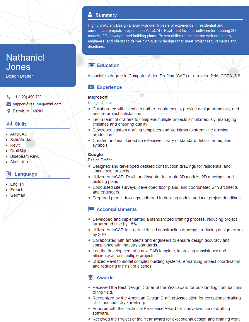
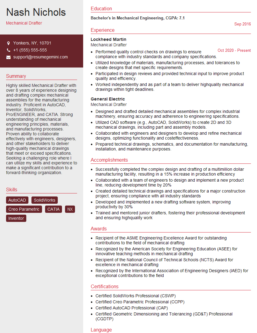
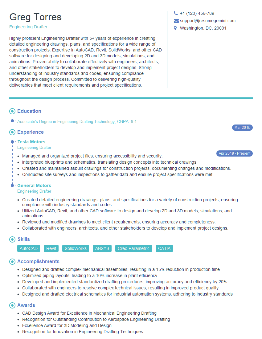
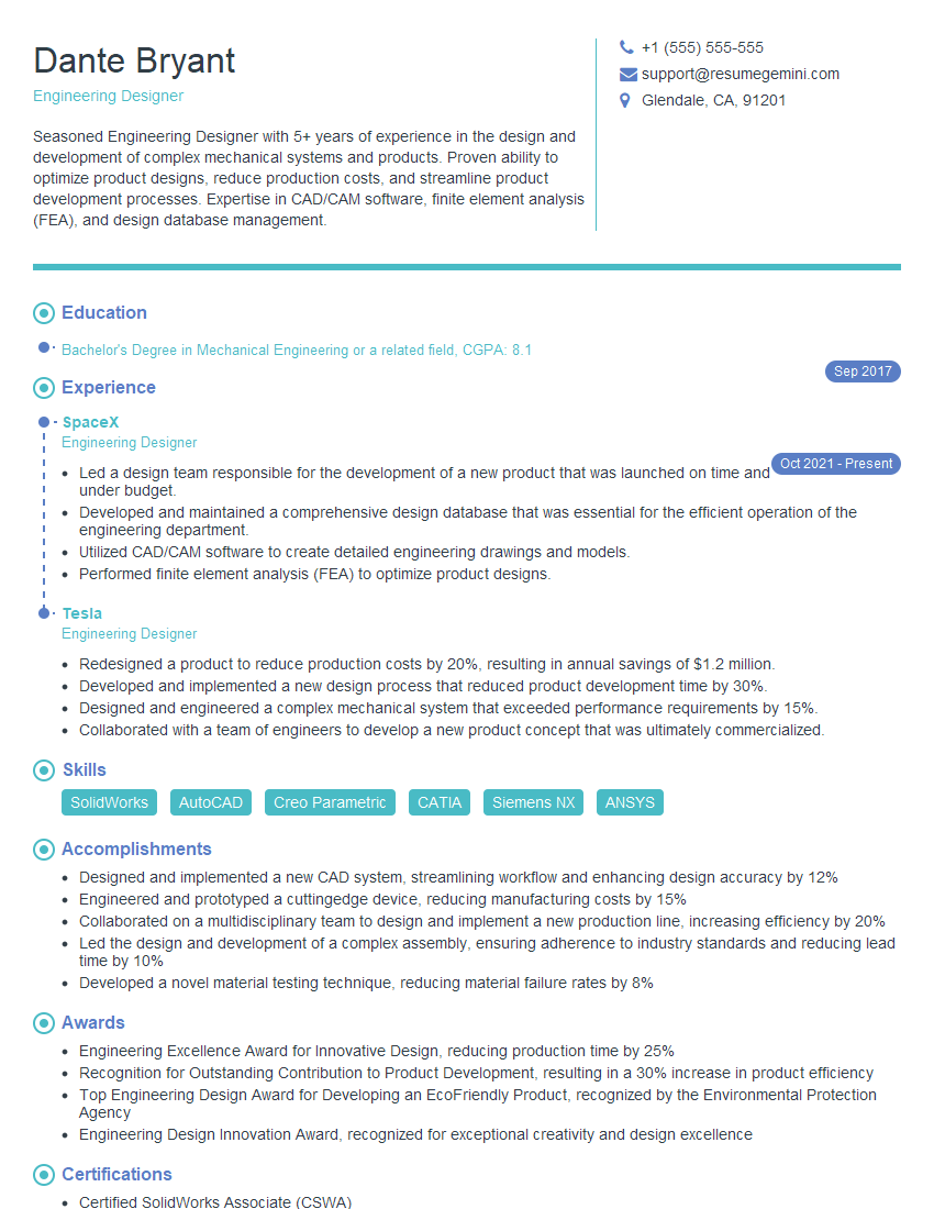
Mastering Engineering Drawing Standards is crucial for a successful career in engineering, demonstrating your attention to detail and technical proficiency. A strong command of these standards significantly enhances your employability and opens doors to more challenging and rewarding opportunities. Building an ATS-friendly resume is essential to get your application noticed. ResumeGemini is a trusted resource to help you create a professional and impactful resume that highlights your skills and experience. We provide examples of resumes tailored to Engineering Drawing Standards to guide you in crafting your own compelling application. Take the next step and create a resume that showcases your expertise effectively.
Explore more articles
Users Rating of Our Blogs
Share Your Experience
We value your feedback! Please rate our content and share your thoughts (optional).
What Readers Say About Our Blog
Hi, I have something for you and recorded a quick Loom video to show the kind of value I can bring to you.
Even if we don’t work together, I’m confident you’ll take away something valuable and learn a few new ideas.
Here’s the link: https://bit.ly/loom-video-daniel
Would love your thoughts after watching!
– Daniel
This was kind of a unique content I found around the specialized skills. Very helpful questions and good detailed answers.
Very Helpful blog, thank you Interviewgemini team.


