Interviews are opportunities to demonstrate your expertise, and this guide is here to help you shine. Explore the essential Knowledge of Low-Voltage and Medium-Voltage Systems interview questions that employers frequently ask, paired with strategies for crafting responses that set you apart from the competition.
Questions Asked in Knowledge of Low-Voltage and Medium-Voltage Systems Interview
Q 1. Explain the difference between low-voltage and medium-voltage systems.
The distinction between low-voltage and medium-voltage systems primarily lies in their voltage levels. Low-voltage systems typically operate at voltages below 1000V AC or 1500V DC, while medium-voltage systems operate between 1000V AC and 35,000V AC. This difference significantly impacts the design, safety protocols, and equipment used. Low-voltage systems are commonly found in homes and small businesses, powering everyday appliances. Medium-voltage systems, on the other hand, are used for electricity distribution across larger areas, supplying power to substations and industrial facilities. The increased voltage in medium-voltage systems allows for efficient transmission over longer distances with lower energy losses, but demands rigorous safety measures.
Q 2. Describe the safety precautions for working with low-voltage and medium-voltage systems.
Working with both low-voltage and medium-voltage systems requires strict adherence to safety regulations. For low-voltage systems, this includes ensuring proper insulation, using appropriate tools and protective equipment like insulated gloves and safety glasses, and always de-energizing circuits before working on them. Never assume a circuit is de-energized; always verify using a voltage tester. For medium-voltage systems, the safety precautions are significantly more stringent. Lockout/Tagout procedures are mandatory before any work commences to prevent accidental energization. Specialized high-voltage protective equipment, including insulated tools, protective suits, and arc flash protection, are essential. Working near energized medium-voltage equipment necessitates specific training and certifications. A thorough risk assessment should be undertaken before any task begins. Think of it like this: working with low voltage is like handling a garden hose; medium voltage is like handling a fire hose – proper precautions are vital to prevent serious injury or death.
Q 3. What are the common types of protective devices used in low-voltage and medium-voltage systems?
Protective devices are crucial for safeguarding both low-voltage and medium-voltage systems. In low-voltage systems, common devices include fuses, circuit breakers (both miniature circuit breakers – MCBs – and residual current devices – RCDs), and surge protection devices (SPDs). Fuses and circuit breakers interrupt the current flow in case of overloads or short circuits. RCDs protect against electric shocks by detecting ground faults. SPDs mitigate voltage surges caused by lightning strikes or switching transients. Medium-voltage systems employ more sophisticated protective devices such as: current transformers (CTs) and voltage transformers (VTs) for monitoring current and voltage levels; circuit breakers with higher interrupting capacities; protective relays that detect faults and initiate tripping actions; and lightning arresters to protect against surges. The choice of protective devices depends on the system’s characteristics, load requirements, and fault current levels.
Q 4. Explain the principles of grounding and earthing in power systems.
Grounding and earthing are essential for safety and system stability in power systems. Grounding connects the non-current-carrying metal parts of equipment to the earth, providing a low-impedance path for fault currents. This helps prevent electric shock and protects against overvoltages. Earthing, often used interchangeably with grounding, involves connecting the neutral point of a transformer or generator to the earth. This helps stabilize the system voltage and provides a reference point for the electrical system. Imagine a metal fence during a thunderstorm; grounding acts as the lightning rod, providing a safe path for the current to disperse into the ground, preventing damage to the fence (equipment) and avoiding electrocution. Effective grounding and earthing reduce the risk of electrical hazards and improve the overall reliability and performance of the power system.
Q 5. What are the different types of cables used in low-voltage and medium-voltage systems?
The selection of cables depends on voltage level, current carrying capacity, environmental conditions, and installation requirements. Low-voltage systems often use flexible PVC insulated cables for wiring within buildings. These cables are relatively inexpensive and easy to install. For higher currents or demanding applications, armored cables or multi-core cables may be used. Medium-voltage systems utilize cables with higher insulation levels and greater mechanical strength, often using XLPE (cross-linked polyethylene) insulation for enhanced dielectric properties. These cables are generally larger in diameter and often installed underground or in overhead lines, requiring specialized installation techniques and equipment. For example, a simple light switch circuit in a home would use low-voltage flexible cable, whereas supplying a large industrial motor might require a medium-voltage XLPE cable with sufficient current carrying capacity and appropriate protection.
Q 6. How do you perform a load calculation for a low-voltage system?
A load calculation for a low-voltage system involves determining the total power demand of all connected appliances and equipment. This is crucial for selecting appropriate circuit breakers, cables, and other components. The process typically involves: 1. **Identifying all loads**: List all devices and their power ratings (in watts or kilowatts). 2. **Determining the load type**: Specify if the load is resistive (e.g., heaters), inductive (e.g., motors), or capacitive (e.g., some electronic devices). 3. **Calculating the total power demand**: Sum up the power ratings of all loads. 4. **Determining the total current**: Divide the total power by the system voltage to obtain the total current. 5. **Applying demand factors**: Consider that not all loads operate simultaneously. Apply appropriate demand factors to reduce the calculated load. 6. **Selecting appropriate components**: Choose circuit breakers, cables, and other components with sufficient capacity to handle the calculated load and comply with safety standards. For example, if the total calculated load is 15 Amps, a 20 Amp circuit breaker would be selected to provide a safety margin.
Q 7. What are the common causes of faults in low-voltage and medium-voltage systems?
Faults in low-voltage and medium-voltage systems can stem from various sources. Common causes in low-voltage systems include: short circuits (due to damaged insulation or faulty wiring), overloads (exceeding the capacity of circuits), loose connections, and equipment failures. In medium-voltage systems, additional factors come into play such as: insulation degradation due to aging or environmental factors, lightning strikes, and tree branches contacting overhead lines. Other common issues include: equipment malfunctions (transformers, circuit breakers), poor maintenance, and external events such as accidents. Regular inspection and maintenance programs, including thermal imaging and insulation testing, are essential for preventing faults and ensuring safe operation of both low-voltage and medium-voltage systems. Prompt fault detection and repair are crucial to minimize downtime and prevent further damage.
Q 8. Describe the process of troubleshooting a fault in a low-voltage system.
Troubleshooting a low-voltage fault involves a systematic approach prioritizing safety. First, isolate the faulty circuit by switching off the relevant breaker or isolating switch. This is crucial to prevent injury. Next, verify the fault using a multimeter to check for voltage, continuity, and resistance. A lack of voltage might indicate a tripped breaker or blown fuse upstream. A lack of continuity suggests a broken wire or faulty component. High resistance might point to a loose connection or a failing device.
Then, inspect visually for obvious problems like loose connections, damaged wiring, or burnt components. This often reveals the culprit immediately. For instance, a charred wire insulation is a clear sign of overheating. If the visual inspection is inconclusive, use a continuity tester on all conductors and components within the circuit to identify any breaks in the circuit.
Systematic tracing from the power source to the load will pinpoint the exact location of the fault. Remember, always use appropriate safety precautions like insulated tools and personal protective equipment (PPE). Finally, repair or replace the faulty component and test the system thoroughly before restoring power. For example, replacing a faulty switch or repairing a loose connection. Documenting the troubleshooting process is vital for future reference.
Q 9. Explain the operation of a circuit breaker.
A circuit breaker is an electromechanical device designed to protect an electrical circuit from damage caused by overload or short circuit currents. Think of it as a safety switch that automatically interrupts the flow of current when it detects an unsafe condition. It works using an electromagnetic mechanism.
When the current flowing through the circuit exceeds a predetermined threshold (either due to an overload or a short circuit), the electromagnetic coil within the breaker generates a strong magnetic field. This field triggers a mechanism that quickly separates the contacts within the breaker, interrupting the flow of current. Some circuit breakers also incorporate a thermal element that responds to prolonged overload conditions. This thermal element bends when excessive heat is generated, causing the contacts to separate.
After a trip, the breaker needs to be manually reset. This allows the breaker to be ready for the next operation. Circuit breakers are crucial for electrical safety, preventing fires and equipment damage.
Q 10. What are the different types of transformers used in power systems?
Transformers are essential components in power systems, used to change the voltage level of AC electricity. Different types cater to various needs.
- Power Transformers: These are large, high-power transformers used in substations to step-up voltage for transmission and step-down voltage for distribution. They’re built for high efficiency and reliability and often have multiple windings for various voltage levels.
- Distribution Transformers: These smaller transformers are found on power poles or underground vaults, stepping down voltage for local distribution to homes and businesses. They typically have a lower power rating than power transformers.
- Instrument Transformers: These are used to measure high voltages and currents safely. Current transformers (CTs) step down current for measurement, and potential transformers (PTs) step down voltage. They provide isolated and scaled-down signals for metering and protection equipment.
- Isolation Transformers: These transformers provide electrical isolation between the input and output circuits. They are commonly used to reduce the risk of electrical shocks and prevent ground faults from affecting sensitive equipment.
- Autotransformers: Unlike standard transformers, these have a single winding with a tap to provide voltage transformation. They are more compact and efficient than conventional transformers but lack electrical isolation between the input and output.
The choice of transformer type depends on the specific application requirements, including voltage levels, power rating, efficiency needs, and safety considerations.
Q 11. Explain the principle of operation of a relay.
Relays are electromechanical or electronic switching devices that sense abnormal conditions in a power system and initiate corrective actions. Think of them as intelligent switches that protect equipment and prevent widespread outages.
A relay operates based on a specific input signal, such as voltage, current, or frequency. When the input signal exceeds a predefined threshold (indicating a fault), the relay activates its contacts, closing or opening circuits. This action can initiate various protective measures, such as tripping a circuit breaker, sounding an alarm, or activating other safety devices.
For example, an overcurrent relay will trip a circuit breaker if the current in a circuit exceeds its rated value, protecting the equipment from damage due to an overload or short circuit. Different types of relays respond to various fault conditions, including overvoltage, undervoltage, ground faults, and phase imbalances. Modern relays incorporate sophisticated microprocessor technology for increased accuracy, speed, and communication capabilities.
Q 12. How do you select the appropriate size of conductor for a given application?
Selecting the appropriate conductor size involves considering several factors, ensuring safe and efficient operation. The primary factors are:
- Current Carrying Capacity (Ampacity): The conductor must be large enough to carry the expected current without overheating. Ampacity is affected by the conductor material (copper or aluminum), insulation type, installation method (e.g., buried, in conduit), and ambient temperature.
- Voltage Drop: Excessive voltage drop along the conductor can lead to poor performance of connected equipment. This necessitates using larger conductors for longer runs or higher currents.
- Safety Regulations: National electrical codes (like NEC in the US) specify minimum conductor sizes based on current, voltage, and installation methods.
- Economic Considerations: Larger conductors are more expensive. A cost-benefit analysis should balance safety, performance, and economic feasibility.
Calculation Example: To determine the size, you might use the following formula (simplified): Conductor Size = (Current × Distance × Voltage Drop Factor) / Voltage Drop. You need to consult tables provided in electrical codes and manufacturers’ data for accurate selection, taking into account all relevant factors.
Q 13. What are the requirements for electrical safety in accordance with relevant codes and standards?
Electrical safety requirements are paramount and vary depending on location and application, but generally adhere to internationally recognized codes and standards such as the National Electrical Code (NEC) in the US, or IEC standards internationally. These regulations aim to protect people and equipment from electrical hazards. Key aspects include:
- Grounding and Bonding: Proper grounding ensures a safe path for fault currents to earth, preventing dangerous voltages from appearing on exposed metal parts. Bonding connects metallic parts to equalize voltage and prevent dangerous potential differences.
- Overcurrent Protection: Circuit breakers, fuses, and other protective devices prevent excessive current from damaging equipment or causing fires.
- Insulation: Adequate insulation protects conductors from contact, preventing shocks and short circuits. Insulation materials and ratings must meet code requirements.
- Wiring Methods: Wiring must be installed according to code provisions to prevent damage and ensure safety. This includes proper support, routing, and protection from mechanical damage.
- Arc Flash Protection: For high-voltage systems, arc flash protection is critical to mitigate the risks of arc flashes, which are extremely hazardous electrical events. This involves using appropriate personal protective equipment (PPE) and implementing engineering controls to reduce the energy of arc flashes.
- Lockout/Tagout Procedures: Proper lockout/tagout procedures ensure that electrical equipment is de-energized and secured before maintenance or repair, preventing accidental energization and injuries.
Regular inspections and maintenance are crucial to ensure continued compliance and safety.
Q 14. Explain the concept of voltage drop and its significance.
Voltage drop refers to the reduction in voltage between the source and the load in an electrical circuit. It’s caused by the resistance of the conductors carrying the current. Imagine water flowing through a pipe – the narrower the pipe (higher resistance), the greater the pressure drop along the length of the pipe (higher voltage drop).
The significance of voltage drop is that it affects the performance of connected equipment. Excessive voltage drop can lead to underperformance, overheating, motor failure, and reduced efficiency. It also impacts the quality and reliability of the electrical system. In lighting circuits, it can result in dimmer lights or premature lamp failure. In motor circuits, it can cause motors to run slower, draw more current, and overheat.
Voltage drop is calculated using Ohm’s Law and is influenced by the conductor’s resistance, current, and length. Engineers carefully consider voltage drop during the design phase to ensure that it stays within acceptable limits specified by the relevant standards. Appropriate conductor sizes are selected to minimize voltage drop, ensuring efficient and reliable operation.
Q 15. How do you calculate the power factor and its importance in power systems?
Power factor is the ratio of real power (kW) to apparent power (kVA) in an AC circuit. It essentially represents how efficiently electrical power is used. A power factor of 1 indicates perfect efficiency (all apparent power is real power), while a power factor less than 1 signifies that some power is wasted as reactive power. We calculate it using the formula: Power Factor (PF) = Real Power (kW) / Apparent Power (kVA) Apparent power is calculated as √(Real Power² + Reactive Power²).
Imagine you’re filling a bucket (real power) with water from a hose (apparent power). A low power factor means some water is spraying all over the place (reactive power) instead of going into the bucket. This wasted water is like wasted energy in the power system.
Importance in power systems: A low power factor leads to higher electricity bills because you’re paying for more apparent power than you’re actually using. It also causes increased current flow in the system, leading to higher losses in transmission and distribution lines, requiring larger equipment (transformers, cables) to handle the increased current. Improving the power factor is crucial for energy efficiency and cost savings.
Career Expert Tips:
- Ace those interviews! Prepare effectively by reviewing the Top 50 Most Common Interview Questions on ResumeGemini.
- Navigate your job search with confidence! Explore a wide range of Career Tips on ResumeGemini. Learn about common challenges and recommendations to overcome them.
- Craft the perfect resume! Master the Art of Resume Writing with ResumeGemini’s guide. Showcase your unique qualifications and achievements effectively.
- Don’t miss out on holiday savings! Build your dream resume with ResumeGemini’s ATS optimized templates.
Q 16. What is the purpose of a surge arrester?
A surge arrester, also known as a surge protector, is a device designed to protect electrical equipment from voltage surges and transients. These surges can be caused by lightning strikes, switching operations, or faults in the power system. They operate by diverting excess voltage to the ground, preventing it from damaging sensitive equipment.
Think of it as a pressure relief valve in a boiler. When the pressure gets too high, the valve opens to release steam and prevent an explosion. Similarly, a surge arrester protects electrical equipment by diverting excessive voltage to ground, preventing damage.
Surge arresters usually employ metal-oxide varistors (MOVs) or gas discharge tubes as their main components. MOVs are non-linear resistors that exhibit a very low resistance at high voltages, effectively diverting the surge. Gas discharge tubes use a gas gap that ionizes and conducts when the voltage exceeds a certain threshold.
Q 17. Describe different types of busbars and their applications.
Busbars are conductive bars used to distribute power in electrical systems. Different types are used depending on the application and voltage level.
- Solid busbars: These are made from solid copper or aluminum bars and are commonly used in low-voltage systems. They are simple, reliable, and relatively inexpensive. Their current carrying capacity depends on their cross-sectional area and the material used.
- Tubular busbars: These are hollow copper or aluminum tubes, often used where higher current carrying capacity or better heat dissipation is required. The hollow design allows for better cooling.
- Hollow Core Busbars: These are used in high current applications, allowing for better cooling and greater flexibility in the design.
- Plate busbars: Used in high voltage applications offering greater surface area for heat dissipation and increased current capacity.
- Modular busbars: Designed for flexibility and scalability, often found in industrial settings.
Applications vary widely depending on the type and size of the busbar. Low-voltage solid busbars are prevalent in switchboards and distribution panels. Larger tubular or plate busbars are commonly seen in substations and power distribution networks.
Q 18. What are the advantages and disadvantages of using different types of insulators?
Insulators are crucial components preventing current flow between conductors or between conductors and ground. Various types exist, each with advantages and disadvantages.
- Porcelain insulators: Inexpensive, durable, and widely used in low- and medium-voltage systems. However, they can be brittle and susceptible to damage from mechanical stress or thermal shock.
- Glass insulators: High dielectric strength and excellent resistance to weather, but more fragile than porcelain and more prone to damage from thermal shock.
- Polymer insulators: Lightweight, flexible, and resistant to pollution. They offer excellent hydrophobic properties (repelling water), minimizing flashover problems. However, their long-term performance under UV radiation and extreme temperatures needs to be carefully considered.
The choice of insulator depends on several factors including voltage level, environmental conditions, mechanical strength requirements, and cost. For example, polymer insulators are often favored in polluted environments due to their superior pollution performance.
Q 19. Explain the operation of a capacitor bank in power factor correction.
Capacitor banks are used for power factor correction by injecting leading reactive power into the system. This leading reactive power compensates for the lagging reactive power consumed by inductive loads (like motors and transformers), bringing the overall power factor closer to unity.
Think of it like balancing a seesaw. Inductive loads tilt the seesaw towards lagging power. The capacitor bank adds leading reactive power to balance the seesaw, making it level. This represents a more efficient use of power.
The size of the capacitor bank is carefully calculated based on the load’s reactive power demand and the desired power factor improvement. They are typically switched on and off automatically or manually to maintain the desired power factor.
Q 20. What is the difference between a single-phase and a three-phase system?
The key difference lies in the number of phases and the resulting voltage and current waveforms.
- Single-phase systems: Use only two wires (one hot and one neutral) to provide power. The voltage and current are sinusoidal waveforms with a single frequency. Commonly used in residential applications.
- Three-phase systems: Use three hot wires and a neutral wire (in some configurations). The three hot wires carry currents that are 120 degrees out of phase with each other. This results in a more balanced and efficient power distribution, making it ideal for industrial and commercial applications. Three-phase systems deliver more power for the same amount of conductor material and produce a more constant torque in motors compared to single phase motors.
In essence, three-phase systems are more efficient and better suited for high-power applications because they offer better power distribution and utilize conductors more effectively.
Q 21. Explain the concept of power system stability.
Power system stability refers to the ability of the system to maintain synchronism between generators after being subjected to a disturbance, like a fault or sudden load change. If the system loses synchronism, generators will start to oscillate and disconnect, leading to a widespread blackout.
Imagine a group of synchronized dancers. Power system stability is like their ability to maintain their synchronized movements even if one dancer stumbles. If the disturbance is small, the system may be able to self-correct and regain stability. But a large enough disturbance can cause the dancers (generators) to fall out of sync and the dance (power supply) to collapse.
Several types of stability exist, including transient stability (immediate response to a fault), dynamic stability (response over a longer period), and small-signal stability (response to small disturbances).
Maintaining power system stability is paramount for reliable electricity supply. Various control measures, such as automatic generation control and power system stabilizers, are used to enhance stability and prevent widespread outages.
Q 22. Describe different types of protective relays and their functions.
Protective relays are the unsung heroes of power system protection, acting as the first line of defense against faults and abnormalities. They constantly monitor the electrical parameters of the system and instantly trip circuit breakers to isolate faulty sections, preventing widespread damage and ensuring safety. Different types cater to specific fault conditions:
Overcurrent Relays: These are the workhorses, detecting excessive current flow due to short circuits or overloads. They come in various types, including instantaneous, time-delayed, and directional relays, each with a specific response time and sensitivity. For example, an instantaneous relay provides immediate protection for extremely fast faults, while a time-delayed relay allows for coordination with other relays to ensure the correct section is isolated.
Differential Relays: These relays compare the current entering and leaving a protected zone (like a transformer or generator). Any significant difference indicates an internal fault, triggering the relay. They are highly sensitive and accurate, minimizing unnecessary trips.
Distance Relays: These measure the impedance to a fault along the transmission line. By calculating the distance to the fault, they can isolate the faulty section precisely, even in long transmission lines. They’re crucial for protecting long distances efficiently.
Ground Fault Relays: These are specifically designed to detect ground faults, which can be particularly dangerous. They monitor the current flowing to ground and can be sensitive to both high and low impedance faults.
Overvoltage and Undervoltage Relays: These relays protect equipment from voltage abnormalities that can damage sensitive components or lead to instability in the power system.
The choice of relay depends on the specific application and the characteristics of the protected equipment. Careful coordination between different relays is critical to avoid cascading failures.
Q 23. What is the role of SCADA in power system monitoring and control?
SCADA, or Supervisory Control and Data Acquisition, is the central nervous system of a modern power system. It provides a comprehensive view of the entire system, enabling operators to monitor, control, and manage it efficiently. Think of it as a sophisticated dashboard showing real-time data from various points across the network.
Its role encompasses:
Real-time Monitoring: SCADA collects data from numerous Remote Terminal Units (RTUs) and intelligent electronic devices (IEDs) placed across the power system. This data includes voltage, current, power flow, equipment status, and more, providing a clear picture of the system’s health.
Control and Automation: Operators can remotely control various aspects of the system through the SCADA interface, such as switching circuit breakers, adjusting voltage levels, and managing power flow. This enhances operational efficiency and enables rapid response to emergencies.
Alarm Management: SCADA systems generate alarms when parameters deviate from predefined limits, alerting operators to potential problems and enabling timely intervention. This prevents small issues from escalating into major outages.
Data Logging and Reporting: SCADA logs vast amounts of data, providing valuable historical information for analysis, performance evaluation, and future planning. This historical data can be used for trend analysis and preventative maintenance.
In essence, SCADA ensures reliable and efficient operation of the power system, maximizing uptime and minimizing disruptions.
Q 24. Explain the importance of harmonic analysis in power systems.
Harmonic analysis is crucial in power systems because it helps identify and mitigate the negative impacts of harmonic currents and voltages. Harmonics are unwanted sinusoidal waveforms with frequencies that are multiples of the fundamental frequency (typically 50Hz or 60Hz). They’re introduced by nonlinear loads like rectifiers, variable speed drives, and computers.
Their presence can lead to several problems:
Overheating of equipment: Harmonics can cause excessive heating in transformers, cables, and other components, potentially leading to premature failure.
Malfunction of protective relays: Harmonics can interfere with the operation of protective relays, leading to incorrect tripping or failure to protect the system.
Increased power losses: Harmonics increase the overall power losses in the system, leading to reduced efficiency.
Interference with communication systems: Harmonics can introduce noise and interference into communication and control systems.
By performing harmonic analysis, engineers can identify the sources of harmonics, quantify their levels, and implement mitigation strategies such as harmonic filters, active power filters, and proper load balancing. This ensures the stable and reliable operation of the power system.
Q 25. Describe your experience with different types of electrical testing equipment.
Throughout my career, I’ve extensively used various electrical testing equipment, essential for ensuring the safety and reliability of electrical systems. My experience includes:
Multimeters: For basic measurements of voltage, current, and resistance – a fundamental tool for any electrical work.
Clamp meters: Ideal for non-intrusive current measurements, useful for troubleshooting circuits without disconnecting wires.
Insulation resistance testers (Meggers): These are crucial for evaluating the insulation quality of cables and equipment, preventing dangerous ground faults.
Power quality analyzers: Advanced tools used to analyze voltage waveforms and detect harmonic distortions and other power quality issues.
Partial discharge detectors: These sophisticated instruments help detect early signs of insulation degradation in high-voltage equipment, preventing catastrophic failures.
High-voltage testers: For testing insulation integrity of high-voltage equipment, confirming its ability to withstand operating voltages and prevent breakdowns.
Proficiency with these tools is critical for diagnosing faults, ensuring system integrity, and preventing safety hazards. I am always careful to select the appropriate equipment for the specific task and to follow all safety procedures.
Q 26. How do you ensure compliance with relevant safety regulations during electrical work?
Safety is paramount in electrical work. I strictly adhere to relevant safety regulations, including the National Electrical Code (NEC) and OSHA standards, to ensure my safety and the safety of others. My safety protocols include:
Lockout/Tagout procedures: Before working on any energized equipment, I always follow strict lockout/tagout procedures to de-energize and isolate the circuits, preventing accidental energization.
Personal Protective Equipment (PPE): I consistently use appropriate PPE, including safety glasses, insulated gloves, safety shoes, and arc flash protection as needed, based on the specific risks involved.
Proper grounding and bonding: I ensure proper grounding and bonding techniques are implemented to prevent electrical shocks and minimize the risk of electrical hazards.
Working at heights safety: When working at heights, I use appropriate fall protection equipment and follow all relevant safety procedures.
Regular safety training: I participate in regular safety training programs to stay updated on the latest safety regulations and best practices.
I believe that a proactive approach to safety, coupled with rigorous adherence to regulations and procedures, is the cornerstone of successful and hazard-free electrical work.
Q 27. Explain your experience with power system simulation software.
I have extensive experience using various power system simulation software packages, including ETAP, PSCAD, and PowerWorld Simulator. These tools are invaluable for analyzing and designing power systems, allowing us to model complex scenarios without the need for costly physical testing.
My experience involves:
Steady-state analysis: Performing load flow studies to analyze voltage profiles, power flows, and system stability under normal operating conditions.
Transient stability analysis: Simulating the system’s response to faults and disturbances, to ensure the system’s stability and prevent cascading outages.
Fault analysis: Calculating fault currents and identifying protective device settings to ensure effective system protection.
Harmonic analysis: Modeling the impact of harmonic sources on the system and designing harmonic mitigation strategies.
Protection coordination studies: Analyzing the coordination between protective relays to ensure that the correct equipment is tripped during faults.
These simulations help in designing more robust, reliable, and efficient power systems. The results are used to optimize system operation, reduce costs, and enhance safety.
Q 28. Describe a challenging project you faced and how you overcame it.
One challenging project involved troubleshooting intermittent outages in a large industrial facility. The outages were unpredictable, affecting different parts of the facility at various times, making diagnosis extremely difficult. Initial investigations, including visual inspections and basic tests, yielded no conclusive results.
My approach involved a systematic investigation:
Comprehensive data acquisition: I installed advanced power quality monitoring equipment to collect detailed data on voltage, current, and harmonic distortions during the outages. This provided a comprehensive view of the electrical events.
Advanced analysis: I used power system simulation software to model different scenarios and test various hypotheses based on the data gathered. This helped isolate the potential causes.
Targeted testing: Based on the simulations, I conducted specific tests on suspected components, including insulation resistance testing and thermal imaging, to pinpoint the root cause.
Collaboration: I collaborated with other engineers and technicians to ensure efficient and thorough troubleshooting.
Ultimately, the analysis revealed that the outages were caused by loose connections in a critical busbar within a heavily loaded section of the facility. Once these were tightened and properly secured, the intermittent outages ceased completely. This experience emphasized the value of meticulous data collection, advanced analysis, and collaborative problem-solving in resolving complex power system issues.
Key Topics to Learn for Knowledge of Low-Voltage and Medium-Voltage Systems Interview
- Low-Voltage Systems: Fundamentals: Understanding basic principles like Ohm’s Law, Kirchhoff’s Laws, and power calculations in low-voltage circuits. Consider practical applications in residential wiring and building automation systems.
- Medium-Voltage Systems: Transmission and Distribution: Explore the principles of power transmission and distribution at medium voltage levels. Focus on understanding transformers, protection schemes (relays, circuit breakers), and safety protocols.
- Protective Devices and Safety Procedures: Master the operation and application of various protective devices used in both low and medium-voltage systems, emphasizing safety regulations and best practices. This includes understanding arc flash hazards and mitigation techniques.
- System Design and Analysis: Develop your ability to analyze and design simple low and medium-voltage systems. This involves load calculations, cable sizing, and understanding voltage drop considerations.
- Troubleshooting and Diagnostics: Practice diagnosing faults and troubleshooting issues in both low and medium-voltage systems. Develop your skills in using diagnostic tools and interpreting system data.
- AC/DC Systems and Conversion: Understand the differences between AC and DC systems and explore the methods and technologies used for conversion between them (e.g., rectifiers, inverters).
- Relevant Standards and Codes: Familiarize yourself with industry standards and codes of practice relevant to low and medium-voltage systems in your region. Understanding these ensures compliance and safety.
Next Steps
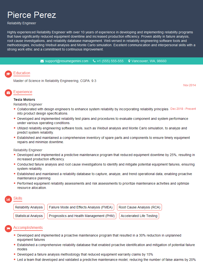
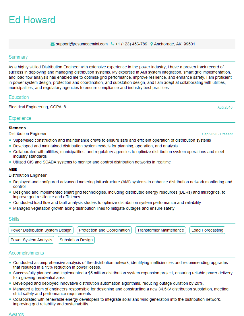
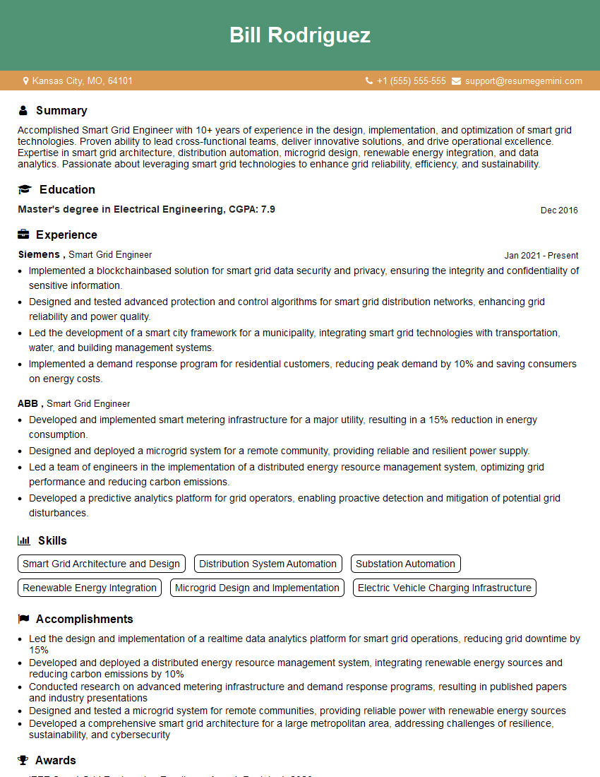
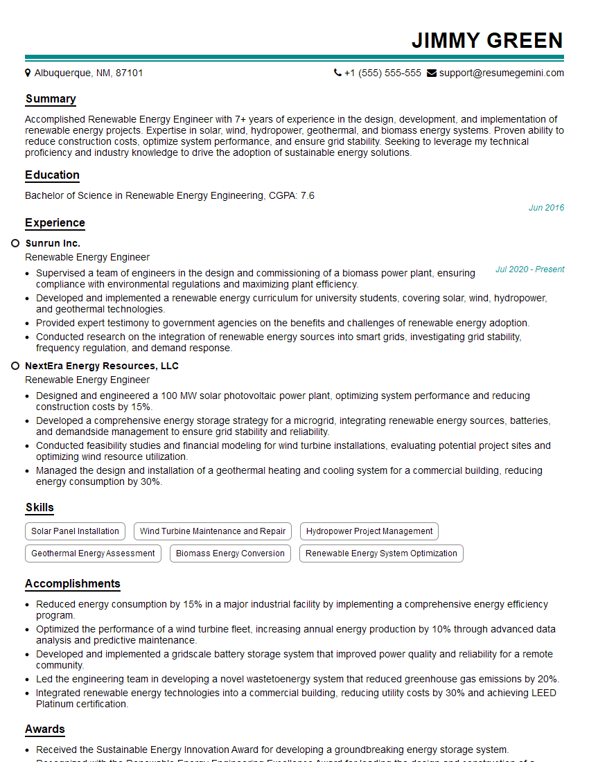
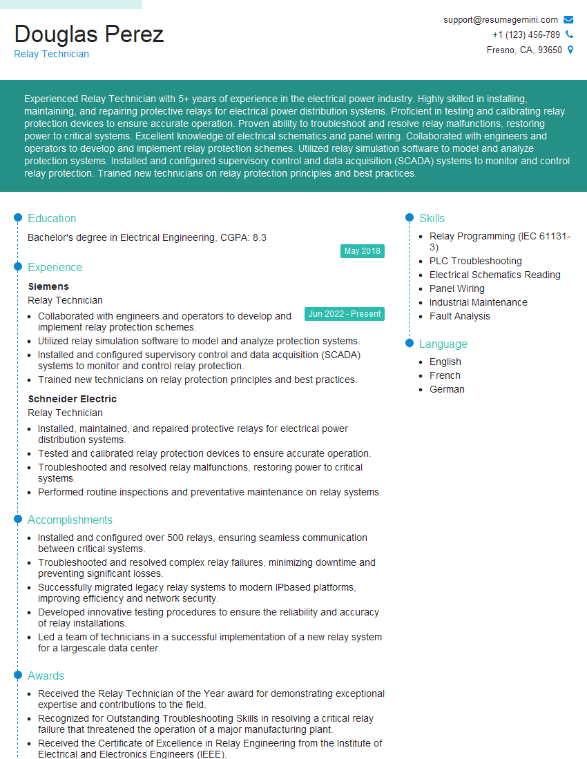
Mastering knowledge of low and medium-voltage systems is crucial for career advancement in the electrical engineering and power systems fields. It opens doors to exciting roles with increased responsibility and higher earning potential. To maximize your job prospects, it’s essential to present your skills effectively. Creating an ATS-friendly resume is paramount in getting your application noticed by recruiters and hiring managers. ResumeGemini can be a valuable tool in this process, helping you craft a professional and impactful resume that highlights your expertise. Examples of resumes tailored to showcase Knowledge of Low-Voltage and Medium-Voltage Systems are available to help guide your efforts.
Explore more articles
Users Rating of Our Blogs
Share Your Experience
We value your feedback! Please rate our content and share your thoughts (optional).
What Readers Say About Our Blog
This was kind of a unique content I found around the specialized skills. Very helpful questions and good detailed answers.
Very Helpful blog, thank you Interviewgemini team.
