Are you ready to stand out in your next interview? Understanding and preparing for Metalworking tools interview questions is a game-changer. In this blog, we’ve compiled key questions and expert advice to help you showcase your skills with confidence and precision. Let’s get started on your journey to acing the interview.
Questions Asked in Metalworking tools Interview
Q 1. Explain the difference between a lathe and a milling machine.
Lathes and milling machines are both fundamental machine tools in metalworking, but they perform different operations. Think of a lathe as a spinning top that shapes material by cutting it along its axis of rotation, while a milling machine is like a rotary rasp that removes material from a stationary workpiece, using multiple cutting tools that move across its surface.
A lathe primarily performs turning operations. The workpiece rotates while a cutting tool, held rigidly in a tool post, removes material to create cylindrical shapes, tapers, threads, and more. It’s excellent for creating parts with rotational symmetry.
A milling machine, conversely, uses rotating cutters to remove material from a workpiece that is typically stationary. This allows for a wide variety of operations, including shaping complex surfaces, creating slots, grooves, and pockets. Milling is versatile and capable of creating intricate parts.
In short: Lathes are ideal for rotational parts; milling machines are best for creating complex shapes and features.
Q 2. Describe the various types of cutting tools used in metalworking.
The world of metalworking cutting tools is vast! They can be broadly categorized by their geometry and application. Here are some key types:
- Single-point cutting tools: These have one cutting edge, like those used in lathes to create precise shapes. Examples include turning tools, parting tools, and threading tools. Each is specifically designed for a particular operation.
- Multi-point cutting tools: These have multiple cutting edges, significantly increasing material removal rates. Milling cutters (end mills, face mills, etc.), drills, and reamers are prime examples. They come in various designs depending on the material and the desired finish.
- Carbide tools: Made from tungsten carbide, these tools are extremely hard and wear-resistant, ideal for machining tough materials like hardened steel. They’re more expensive but last considerably longer.
- High-speed steel (HSS) tools: A more common and cost-effective option. They offer a good balance of hardness, toughness, and wear resistance, suitable for many materials.
- Ceramic tools: For exceptionally high-speed and high-temperature applications, ceramic tools provide exceptional wear resistance.
The selection of a cutting tool depends heavily on factors like material properties of the workpiece (hardness, toughness), desired surface finish, and the type of operation being performed. Choosing the wrong tool can lead to tool breakage, poor surface finish, or inefficient machining.
Q 3. What are the safety precautions when operating a CNC machine?
CNC machines are powerful but require meticulous safety procedures. Here are some key precautions:
- Lockout/Tagout (LOTO): Before performing any maintenance or adjustments, always lock out and tag out the power supply to prevent accidental activation.
- Proper guarding: Ensure all safety guards are in place and functioning correctly to prevent accidental contact with moving parts.
- Personal Protective Equipment (PPE): Always wear appropriate safety glasses, hearing protection, and machine-specific protective gear such as gloves and a shop apron.
- Emergency stop buttons: Know the location and operation of all emergency stop buttons and use them appropriately in case of any unusual circumstances.
- Proper training: Never operate a CNC machine without proper training and authorization. Improper operation can lead to serious injury or damage.
- Regular inspection: Routinely inspect the machine for any signs of wear, damage, or loose parts.
- Safe work practices: Keep the work area clean and organized, free of clutter that could cause accidents.
Ignoring these precautions can lead to severe injuries. It’s better to err on the side of caution, rather than risk a serious accident.
Q 4. How do you select the appropriate cutting speed and feed rate for a specific material?
Selecting the right cutting speed and feed rate is crucial for efficient and safe machining. It’s a balance between productivity and tool life. Improper settings can lead to broken tools, poor surface finish, or excessive heat.
The process generally involves consulting manufacturer’s recommendations or material data sheets, usually presented in charts or tables. The material properties (hardness, strength, machinability) play the most critical role.
Cutting speed (V) refers to the rotational speed of the cutting tool. It is typically expressed in feet per minute (fpm) or meters per minute (m/min). Higher speeds are generally better for harder materials, but excessive speeds can cause tool wear and breakage.
Example: Machining aluminum allows for higher cutting speeds than machining stainless steel.
Feed rate (F) represents the rate at which the tool advances into the workpiece. It’s expressed in inches per minute (ipm) or millimeters per minute (mm/min). Higher feed rates increase productivity but might reduce surface quality.
Example: A roughing cut (removal of substantial material) employs a faster feed rate than a finishing cut (creating precise dimensions and smooth surfaces).
A good rule of thumb is to start with conservative settings from a reputable source and then make gradual adjustments based on observations (chip formation, tool wear, surface finish). Monitoring the machine and the process is crucial to find the optimal balance between cutting speed, feed rate, and tool life.
Q 5. Explain the concept of tolerance in metalworking.
Tolerance in metalworking defines the permissible variation in a dimension or a feature. It’s the acceptable range within which a manufactured part can deviate from its specified nominal size without being considered defective. Think of it as the margin of error allowed in the production process.
Tolerances are typically expressed as plus/minus values (+/-), indicating the acceptable upper and lower limits of a dimension. For example, a dimension specified as 10.00 mm +/- 0.05 mm means that any value between 9.95 mm and 10.05 mm is acceptable. This is usually defined in drawings and specifications.
The level of tolerance required depends on the application. Parts for critical aerospace applications require much tighter tolerances than those used in less demanding applications. The tighter the tolerance, the more challenging and expensive the manufacturing process becomes.
Effective tolerance control ensures that parts fit together properly and function as intended. It requires precise measurement and controlled manufacturing processes to achieve consistent results within the specified tolerance limits. Without proper tolerance control, components might not be compatible, resulting in functional failures, rework, or scrap.
Q 6. What are the different types of welding processes?
Welding is a joining process that fuses materials together by applying heat, pressure, or both. There are numerous welding processes, each with its own advantages and limitations. Here are some major types:
- Shielded Metal Arc Welding (SMAW): A common and versatile process, also known as stick welding. It uses a consumable electrode that melts to form the weld. The arc is shielded from the atmosphere by a flux coating on the electrode.
- Gas Metal Arc Welding (GMAW): Often referred to as MIG welding, it uses a continuous wire electrode that is fed automatically into the weld pool. A shielding gas (usually argon or CO2) protects the weld from contamination.
- Gas Tungsten Arc Welding (GTAW): Also known as TIG welding, this process uses a non-consumable tungsten electrode. The weld is protected by an inert shielding gas, typically argon. It produces high-quality welds, but requires more skill.
- Resistance Welding (RW): This process uses electrical resistance to generate heat at the joint and fuses the metals together. Spot welding and seam welding are common examples.
- Oxy-Fuel Welding (OFW): This classic process uses a mixture of oxygen and fuel gas (acetylene, propane) to generate a flame to melt and join metals. It’s relatively simple but slower than arc welding processes.
The choice of welding process depends on various factors including material type, thickness, joint design, and required weld quality. Each method has a distinct range of applications where it excels.
Q 7. Describe your experience with different types of measuring tools (calipers, micrometers, etc.).
Throughout my career, I’ve extensively used various measuring tools to ensure dimensional accuracy. My experience includes:
- Vernier calipers: These are widely used for measuring linear dimensions with higher precision than a simple ruler. I’ve used them for measuring external and internal diameters, depths, and lengths with accuracy to 0.01 mm or 0.001 inches. I’m adept at reading both the main scale and vernier scale to avoid measurement errors.
- Micrometers: These provide even greater accuracy than calipers, typically measuring to 0.001 mm or 0.0001 inches. I have experience with both outside micrometers and inside micrometers, and I understand the importance of applying proper pressure to ensure consistent and precise readings. I also have experience using digital micrometers, which further streamline the measurement process and reduce reading error.
- Dial indicators: Used to measure minute changes in dimensions and surface irregularities. These tools are indispensable for checking alignment, roundness, and runout. I can confidently use dial indicators for setting up machine tools, checking part geometry, and ensuring dimensional consistency.
- Height gauges: These precise instruments, typically used with a surface plate, are crucial for setting up and checking the dimensional accuracy of workpieces, fixtures, and tooling. I have used them for accurate height measurements and alignment verification.
My proficiency with these tools allows me to detect and correct dimensional inaccuracies quickly, ultimately ensuring high-quality and consistent products. Accuracy is paramount in metalworking, and these tools are my most reliable allies.
Q 8. How do you troubleshoot common problems encountered during machining?
Troubleshooting machining problems requires a systematic approach. It’s like detective work – you need to gather clues and eliminate possibilities. I start by carefully observing the problem: Is it a surface finish issue? Is there excessive vibration? Are the dimensions incorrect? Then I consider the potential sources: the machine itself, the tooling, the workpiece material, or the machining parameters (speed, feed, depth of cut).
- Tooling Issues: Dull or chipped tools are common culprits. I’ll check for wear and replace if necessary. Incorrect tool geometry or improper clamping can also lead to problems. For example, a poorly clamped end mill might chatter, resulting in a rough surface finish. I’d inspect the toolholder and ensure a tight, secure fit.
- Machine Issues: A worn or misaligned machine can cause inaccuracies. I’d look for loose components, worn bearings, or problems with the spindle. Regular machine maintenance is crucial to prevent these issues.
- Workpiece Issues: Internal stresses or inconsistencies in the material can affect machining. For example, a workpiece with internal voids can cause tool breakage. Careful material selection and inspection are vital.
- Machining Parameters: Incorrect cutting parameters (speed, feed, depth of cut) are often the cause of problems like excessive heat generation, tool breakage, or poor surface finish. I’ll consult a machining handbook or use a CAM software’s built-in calculators to optimize parameters for the specific material and tool.
Often, it’s a combination of factors. I systematically check each aspect until I pinpoint the root cause. Detailed record-keeping – noting the process parameters, tool type, and material – helps to identify recurring problems and prevent them in the future. It’s a bit like assembling a jigsaw puzzle, piece by piece.
Q 9. Explain the importance of proper tool maintenance.
Proper tool maintenance is paramount for efficiency, safety, and quality in metalworking. Neglecting maintenance leads to premature tool wear, reduced accuracy, increased downtime, and potentially even accidents.
- Regular Cleaning: Removing chips and debris after each use prevents damage and ensures the tool’s longevity. Compressed air or a brush are usually sufficient.
- Sharpening and Honing: Regular sharpening is critical for maintaining cutting edge geometry and performance. This can involve using specialized grinding machines or sending tools to professional sharpening services. Honing restores the sharpness of already sharpened tools.
- Storage: Tools should be stored in a clean, dry place, ideally in protective cases or racks to prevent damage or corrosion.
- Inspection: Before each use, tools should be visually inspected for cracks, chips, or other damage. Damaged tools should be replaced immediately.
- Lubrication: Some tools, particularly those with moving parts, require periodic lubrication to prevent wear and tear.
Think of it like maintaining a car: regular maintenance prevents larger, more costly repairs down the line. The investment in proper tool maintenance significantly reduces costs and enhances overall productivity.
Q 10. Describe your experience with CAD/CAM software.
I have extensive experience with various CAD/CAM software packages, including Mastercam, Fusion 360, and SolidWorks CAM. My proficiency goes beyond simple part modeling; I’m comfortable with complex toolpath generation, simulation, and optimization.
In a recent project, we were tasked with machining a complex aerospace component with intricate internal features. Using Fusion 360, I designed the part, generated efficient toolpaths that minimized machining time while maintaining tight tolerances, and simulated the machining process to identify potential collisions or issues before production. This simulation capability is invaluable – it saves time and materials by catching errors early on.
I can create and edit various types of toolpaths, including roughing, finishing, drilling, and milling. I understand the importance of optimizing toolpaths for different materials and machine capabilities, ensuring efficient use of resources and maintaining high precision. My expertise extends to post-processing, generating machine-specific code to seamlessly transfer the digital design to the shop floor. I am also proficient in using various simulation features that predict tool deflection, cutting forces and surface finish.
Q 11. How do you interpret engineering drawings?
Interpreting engineering drawings is fundamental to my work. It’s like reading a map that guides the machining process. I look for key information, including dimensions, tolerances, material specifications, surface finish requirements, and annotations.
- Dimensions and Tolerances: Precise measurements are crucial. I pay close attention to tolerances – the allowable deviations from the specified dimensions. Tight tolerances require more precise machining techniques.
- Material Specifications: The drawing specifies the material’s type and grade, which determines the appropriate machining parameters and tooling.
- Surface Finish: The required surface finish – roughness or smoothness – dictates the choice of cutting tools and speeds.
- Views and Sections: Multiple views (front, top, side) and cross-sections are essential for visualizing the part’s three-dimensional geometry.
- Annotations: Notes, symbols, and other annotations provide additional details or instructions.
I’m adept at using various measuring tools – calipers, micrometers – to verify the machined part’s dimensions against the drawing’s specifications. Any discrepancies require careful analysis to identify the source of the error.
Q 12. What are the different types of metal alloys and their properties?
Metal alloys are mixtures of different metallic elements, each imparting unique properties to the alloy. The properties are largely determined by the base metal and the alloying elements present.
- Steels: Iron-carbon alloys, with carbon content influencing hardness and strength. Low-carbon steels are ductile and easily machinable; high-carbon steels are hard and strong but more difficult to machine.
- Aluminum Alloys: Lightweight and corrosion-resistant, with various alloying elements affecting strength, machinability, and castability. They’re widely used in aerospace and automotive applications.
- Titanium Alloys: Known for high strength-to-weight ratio and corrosion resistance. They are extremely difficult to machine due to their hardness and tendency to work-harden.
- Stainless Steels: Iron-based alloys with chromium and other elements for corrosion resistance. Different grades offer varying degrees of machinability and strength.
- Copper Alloys: Include brass (copper-zinc) and bronze (copper-tin), offering excellent electrical conductivity (copper) and corrosion resistance (bronze). Machinability varies with the specific alloy.
Choosing the right alloy is crucial. Consider factors like strength, weight, corrosion resistance, and machinability to select the most appropriate material for the intended application. This requires a deep understanding of the material properties.
Q 13. Explain the process of heat treating metals.
Heat treating is a process that alters a metal’s microstructure by heating and cooling it to specific temperatures and rates. This changes its mechanical properties like hardness, strength, and ductility.
- Annealing: Heating to a high temperature and then slowly cooling, relieving internal stresses and making the metal softer and more ductile. This is often done after cold working to improve machinability.
- Hardening: Heating to a critical temperature (austenitizing), then rapidly cooling (quenching) to create a hard, brittle martensitic structure. This is followed by tempering (below).
- Tempering: Heating the hardened metal to a lower temperature, reducing its brittleness and increasing toughness. The tempering temperature determines the final hardness and strength.
- Normalizing: Heating to a slightly higher temperature than annealing, then air-cooling to refine the grain structure and improve machinability.
The heat-treating process must be carefully controlled, as incorrect temperatures or cooling rates can lead to undesirable results, such as cracking or warping of the workpiece. I always refer to established heat-treating charts and guidelines to ensure that the process is carried out correctly. It’s a precise science involving careful control of temperature and time, often necessitating specialized equipment like furnaces and quenching baths.
Q 14. How do you ensure the quality of your work?
Ensuring quality in my work involves a multi-faceted approach, from initial design to final inspection.
- Careful Planning: Thoroughly reviewing engineering drawings, selecting appropriate tools and materials, and meticulously planning the machining process. This includes optimizing machining parameters to ensure accuracy and efficiency.
- Process Monitoring: Closely monitoring the machining process, paying close attention to cutting speeds, feed rates, and tool wear. Any deviations from the plan are investigated immediately.
- Regular Inspection: Using precise measuring instruments (calipers, micrometers, CMM) to verify the dimensions, tolerances, and surface finish of the machined parts at various stages. This ensures that any errors are detected early.
- Documentation: Maintaining accurate records of the machining process, including parameters, tools used, material properties, and inspection results. This aids in troubleshooting and continuous improvement.
- Continuous Improvement: Regularly reviewing the machining process, identifying areas for improvement, and implementing changes to enhance efficiency, accuracy, and overall quality. This is a cyclical process that is essential for achieving perfection.
Quality is not merely a checklist but a mindset. I strive for excellence in every aspect of my work, from design to final inspection, understanding that quality is not an accident; it is achieved through meticulous planning, execution, and continuous improvement.
Q 15. Describe your experience with different types of grinding wheels.
Grinding wheels are the heart of many metalworking operations, and my experience spans a wide range of types, each suited for specific applications. The selection depends heavily on the material being ground, the desired finish, and the required stock removal rate.
- Abrasive Type: I’ve worked extensively with aluminum oxide wheels (excellent for ferrous metals), silicon carbide wheels (ideal for non-ferrous metals and ceramics), and diamond wheels (for very hard materials like tungsten carbide). The choice here directly impacts the grinding efficiency and surface finish. For instance, a silicon carbide wheel would be preferred for grinding aluminum to achieve a fine finish, whereas aluminum oxide would be better for steel, offering higher stock removal.
- Bond Type: The bond holds the abrasive grains together. Vitrified bonds are the most common and offer good strength and wear resistance. Resinoid bonds are used for high-speed grinding and offer more flexibility. Metallic bonds are extremely durable but can be more brittle. My experience includes selecting the appropriate bond based on the application – a vitrified bond for general-purpose grinding of steel, and a resinoid bond for a high-speed operation on aluminum.
- Grain Size: This determines the surface roughness. Coarser grains (higher number) are for rapid stock removal, while finer grains (lower number) create smoother surfaces. I’ve honed my ability to choose the correct grain size to meet tolerances in various projects, from roughing out a workpiece with a coarse wheel to final finishing with a fine one.
- Wheel Structure: This refers to the porosity of the wheel. Open structure wheels are good for free-cutting operations with less clogging, while closed structure wheels are for finer finishes. I’ve had to adjust the wheel structure based on the material’s tendency to clog, optimizing performance and minimizing downtime.
In one project, we were struggling to achieve a mirror finish on stainless steel components. By switching from a standard vitrified aluminum oxide wheel to a resinoid bond wheel with a finer grain size and open structure, we drastically improved our surface finish and reduced the grinding time significantly.
Career Expert Tips:
- Ace those interviews! Prepare effectively by reviewing the Top 50 Most Common Interview Questions on ResumeGemini.
- Navigate your job search with confidence! Explore a wide range of Career Tips on ResumeGemini. Learn about common challenges and recommendations to overcome them.
- Craft the perfect resume! Master the Art of Resume Writing with ResumeGemini’s guide. Showcase your unique qualifications and achievements effectively.
- Don’t miss out on holiday savings! Build your dream resume with ResumeGemini’s ATS optimized templates.
Q 16. What are the different types of metal finishing processes?
Metal finishing processes aim to enhance a part’s surface properties like appearance, corrosion resistance, and dimensional accuracy. These processes can be broadly categorized as:
- Mechanical Finishing: This includes grinding (as discussed earlier), polishing (using progressively finer abrasives), honing (using fine abrasive stones for precision finishing), and buffing (using soft wheels and compounds for high-luster finishes). I have extensive experience with all these, often using them sequentially to achieve a desired surface.
- Chemical Finishing: This involves using chemical solutions to remove surface imperfections or alter surface properties. Processes like etching, pickling (removing scale or oxides), and electropolishing (electrochemically polishing for a high luster) fall under this category. I’ve utilized pickling to remove surface oxides from steel before painting, ensuring a high-quality finish.
- Electrochemical Finishing: Techniques like electroplating (depositing a thin layer of metal for corrosion protection or aesthetics), anodizing (forming an oxide layer on aluminum for corrosion resistance and color), and electropolishing (mentioned above) belong here. A memorable project involved anodizing aluminum parts for an aerospace application, achieving both the necessary corrosion resistance and a specific color matching the client’s specifications.
- Other Methods: Shot peening (bombarding with small shot to improve fatigue resistance), tumbling (using abrasive media in a rotating barrel for mass finishing), and vibratory finishing (similar to tumbling, but using vibrations) are other crucial methods. I’ve successfully employed shot peening to increase the fatigue life of critical components in many projects.
Q 17. How do you calculate the cutting forces involved in machining?
Calculating cutting forces in machining is crucial for selecting the right machine tools, optimizing cutting parameters, and predicting tool life. It’s a complex process, and precise calculations often involve sophisticated software, but the basic principles remain consistent.
Several empirical models exist, and the choice depends on the specific machining operation (turning, milling, drilling etc.). A common approach involves using equations that relate cutting forces to parameters like:
- Cutting speed (V): The speed at which the tool moves relative to the workpiece.
- Feed rate (f): The distance the tool advances with each revolution (in turning) or per tooth (in milling).
- Depth of cut (d): The depth the tool penetrates into the workpiece.
- Material properties: The material’s strength and machinability significantly influence cutting forces.
- Tool geometry: The tool’s rake angle, relief angle, and nose radius affect cutting forces.
A simplified equation for turning, for instance, could be:
Fc = K * d * fx * VyWhere:
Fcis the cutting force.Kis a material-specific constant.dis the depth of cut.fis the feed rate.Vis the cutting speed.xandyare exponents that depend on the material and cutting conditions.
The values of K, x, and y are often determined experimentally or obtained from material databases. More advanced models consider factors like tool wear and workpiece clamping rigidity. In practice, I often rely on software simulations to accurately predict cutting forces for complex geometries and materials. These simulations not only provide cutting force estimates but also help in predicting tool life and potential problems like chatter.
Q 18. Explain the concept of workholding in machining.
Workholding in machining refers to the method of securely clamping and supporting the workpiece during the machining process. It’s a critical aspect that directly impacts machining accuracy, surface finish, and safety. A poorly designed or executed workholding strategy can result in inaccuracies, vibrations (leading to chatter), tool breakage, and even accidents.
The choice of workholding depends on factors like:
- Workpiece geometry and size: Simple workpieces might be held in a vise, while complex shapes might require specialized fixtures.
- Machining operation: Different operations require different clamping strategies. For example, turning often utilizes chucks or collet systems, while milling may involve fixtures or specialized vise jaws.
- Material properties: The material’s hardness and tendency to deform under clamping pressure will influence the choice of workholding.
- Required accuracy: High-precision work requires robust and accurate workholding systems to minimize vibrations and workpiece deflection.
Common workholding methods include:
- Vices: Simple and versatile for smaller workpieces.
- Chucks: Used for rotating workpieces in turning operations.
- Fixtures: Custom-designed systems for complex shapes or large workpieces.
- Magnetic chucks: For ferrous materials, offering quick setup and versatility.
In one instance, we were struggling with vibrations during the milling of a thin, large aluminum plate. The original workholding system wasn’t providing enough support. By designing a custom fixture with multiple clamping points and strategically placed supports, we eliminated the vibrations, greatly improving surface finish and reducing the risk of tool breakage.
Q 19. Describe your experience with different types of lubricants and coolants.
Lubricants and coolants are essential in metalworking to reduce friction, heat generation, and tool wear, thereby enhancing machining efficiency, surface finish, and tool life. My experience encompasses a broad spectrum of these fluids, each tailored to specific applications.
Types of coolants:
- Water-based coolants: These are cost-effective and provide good cooling, but can contribute to corrosion and require appropriate filtration.
- Oil-based coolants: Offer better lubrication and are less prone to corrosion, but their disposal can be more challenging and they have lower cooling capacity.
- Synthetic coolants: These combine the advantages of water and oil-based coolants, offering superior performance and better environmental friendliness.
- Specialty coolants: Formulated for specific materials (e.g., coolants for aluminum or stainless steel) or operations (e.g., high-speed machining).
My experience includes choosing the correct coolant based on material, operation, and environmental considerations. I have seen first-hand the detrimental effects of using the wrong coolant. In one project, using a water-based coolant on a stainless steel component resulted in surface corrosion. Switching to a synthetic coolant specifically designed for stainless steel solved the problem.
Lubricants often supplement coolants, especially for operations requiring high pressures, like deep drilling or heavy turning. They form a film between the tool and the workpiece, minimizing friction and wear. The selection criteria are similar to coolants, taking into account the material, process, and environmental implications. I have used different types of oil-based and semi-synthetic lubricants for specific applications to optimize the cutting process.
Q 20. How do you handle material defects during production?
Material defects can significantly impact the quality of the final product and the efficiency of the production process. My approach to handling material defects involves a multi-step process that combines proactive measures with effective reactive strategies.
Proactive Measures:
- Incoming Inspection: Rigorous inspection of raw materials upon arrival to identify and reject defective materials. This involves visual inspection, dimensional checks, and sometimes more advanced techniques like ultrasonic testing or X-ray inspection, depending on the material and application.
- Process Monitoring: Regularly monitoring the machining process to detect potential sources of defects, such as incorrect tooling, inadequate workholding, or improper cutting parameters.
- Preventive Maintenance: Regular maintenance of machine tools and equipment to minimize the risk of defects caused by malfunctioning machinery.
Reactive Strategies:
- Defect Identification and Classification: Accurate identification and classification of defects using visual inspection, measurement tools, and sometimes specialized equipment (like microscopy).
- Root Cause Analysis: Investigating the root cause of the defect to prevent its recurrence. This often involves analyzing process parameters, tooling, and material properties.
- Defect Repair or Rejection: Repairing the defect (if feasible) or rejecting the defective part. The decision here depends on the severity of the defect, the cost of repair, and the overall quality requirements.
- Corrective Actions: Implementing corrective actions to prevent similar defects from occurring in the future. This might involve adjusting machine parameters, improving workholding, replacing defective tools, or modifying the production process.
One instance involved discovering internal porosity in a batch of aluminum castings. Through thorough investigation, we traced the issue to a problem in the casting process. Working with the supplier, we corrected the casting parameters, ensuring defect-free material in subsequent batches.
Q 21. What is your experience with different types of presses?
My experience with presses encompasses various types, each suited for specific applications. The selection of a press depends on factors such as the required force, the material being formed, and the desired precision.
- Mechanical Presses: These utilize a crank and flywheel system to generate force. They are versatile, robust, and widely used for various forging, stamping, and pressing operations. I’ve worked extensively with mechanical presses in high-volume production environments, where reliability and consistent force are crucial.
- Hydraulic Presses: These use hydraulic fluid to generate force, offering precise force control and the ability to handle higher tonnage. Hydraulic presses are commonly used for forming large or complex parts, as well as in applications requiring precise force control. In a past project, we used a hydraulic press to form large, intricate sheet metal components for a construction project.
- Pneumatic Presses: Utilizing compressed air, these are suitable for lighter-duty applications and often provide rapid cycle times. I’ve used pneumatic presses in assembly operations, where speed and lower forces were needed.
- Transfer Presses: These are highly automated systems that combine several operations in a single press, enhancing production efficiency. They are particularly useful for complex, high-volume stamping operations. In my experience, transfer presses significantly increase productivity and maintain high levels of precision.
The selection of a press also involves considering factors like press capacity, stroke length, die sets, and safety features. It’s critical to match the press’s capabilities with the specific requirements of the job to optimize efficiency and ensure the safety of the operators. Proper maintenance and safety procedures are paramount when working with presses of all types.
Q 22. Explain the different types of forging processes.
Forging is a metalworking process involving the shaping of metal using localized compressive forces. There are various types, broadly categorized as open-die and closed-die forging.
- Open-die forging: This involves shaping metal between two flat dies. It’s simpler and more versatile for unique shapes but less precise. Imagine hammering a piece of hot metal on an anvil – that’s a basic form of open-die forging. Examples include forging large shafts or creating initial shapes before further processing.
- Closed-die forging: This uses dies with a pre-defined cavity. The metal is forced into the cavity, creating a highly precise part. Think of it like baking a cookie – the cookie cutter is the die, and the dough is the metal. This method produces parts with intricate details and excellent dimensional accuracy. Examples include forging automotive parts like connecting rods or intricate gears.
- Impression-die forging: A subset of closed-die forging where the dies are designed to create a specific shape with precise details. The final shape is quite similar to the die cavity itself.
- Upset forging: This involves shortening and thickening the metal workpiece by compressing it axially. Imagine squashing a cylinder to make it shorter and wider.
- Roll forging: Metal is shaped by passing it through rotating rolls with profiled surfaces. This process is suitable for continuous production of long, relatively simple shapes like rails or rods.
The choice of forging process depends on factors like part complexity, required tolerances, production volume, and material properties.
Q 23. Describe your experience with automated guided vehicles (AGVs) in a metalworking environment.
In my previous role at a large metal fabrication facility, we utilized AGVs extensively for material handling. These autonomous vehicles transported raw materials, work-in-progress, and finished goods between various workstations. Specifically, we used AGVs to move heavy metal sheets from the loading docks to the cutting and forming areas. This significantly improved efficiency by reducing manual handling and minimizing the risk of workplace accidents associated with heavy lifting.
My responsibilities included monitoring AGV operations, troubleshooting malfunctions (such as path planning errors or sensor issues), and coordinating their movements with other production activities. We integrated the AGVs with our ERP system, providing real-time tracking and optimization of material flow. This ensured materials reached the right workstations at the right time, minimizing production delays and optimizing inventory management.
Q 24. How do you ensure the safety of yourself and others in a metalworking environment?
Safety is paramount in a metalworking environment. My approach is multifaceted and includes:
- Adherence to safety protocols: Strict adherence to company safety policies, including the proper use of personal protective equipment (PPE) like safety glasses, hearing protection, and steel-toe boots, is crucial. We conducted regular safety briefings and training sessions to reinforce these procedures.
- Regular machine inspections: Before operating any machine, a thorough inspection is mandatory. This includes checking for any loose parts, damaged components, or potential hazards.
- Proper machine guarding: Ensuring all machines are equipped with and utilize appropriate safety guards to prevent accidental contact with moving parts is essential. This also includes using emergency stop buttons and safety interlocks.
- Housekeeping: Maintaining a clean and organized workspace reduces trip hazards and prevents accidents. This includes proper disposal of scrap metal and regular cleaning of the work area.
- Risk assessment: Proactive identification and mitigation of potential hazards by performing regular risk assessments is key. This might involve identifying potential pinch points, implementing lockout/tagout procedures for maintenance, or establishing safe work practices for specific tasks.
A proactive approach to safety, coupled with a culture of responsibility, is essential in preventing accidents and creating a safe workplace.
Q 25. What is your experience with different types of CNC programming languages?
My experience encompasses various CNC programming languages, primarily focusing on G-code and its variants. I’m proficient in writing and interpreting G-code for both milling and turning operations. I’ve also worked with CAM software that generates G-code from CAD models, significantly speeding up the programming process.
Beyond G-code, I have experience with conversational programming languages offered by some CNC machine manufacturers. These languages simplify the programming process by using more intuitive commands, reducing the steep learning curve for some tasks. However, G-code remains the industry standard, offering the most control and flexibility.
For example, I’ve used G01 X10 Y20 F50 to perform a linear interpolation move in G-code. This command moves the tool to coordinate X10, Y20 at a feed rate of 50 units/minute. My experience also includes adapting existing programs, optimizing toolpaths for efficiency, and troubleshooting programming errors.
Q 26. Describe your experience with robotic automation in metalworking.
My experience with robotic automation in metalworking includes working with robotic arms in several applications, such as welding, material handling, and machine tending. In one project, we integrated a robotic arm with a CNC lathe to automate the loading and unloading of workpieces. This significantly increased production efficiency and reduced operator fatigue. The robot accurately and consistently loaded and unloaded parts, ensuring that the machine ran continuously with minimal downtime.
I’ve also been involved in the programming and setup of these robotic systems, utilizing robot-specific programming languages and software. This requires understanding both the robotic kinematics and the specific requirements of the metalworking process. For example, careful consideration must be given to factors like collision avoidance, cycle time optimization, and the integration with other automated systems. Error handling and safety features were of utmost importance. We used simulations and offline programming to minimize setup time and reduce risks on the factory floor.
Q 27. Explain the process of setting up and operating a CNC milling machine.
Setting up and operating a CNC milling machine involves several steps:
- Program Input/Selection: The first step is to select or create the CNC program (G-code) that defines the machining operations. This program instructs the machine on the toolpaths, speeds, feeds, and other parameters.
- Workpiece Setup: Securely mount the workpiece on the machine’s table using appropriate clamping methods. Ensuring the workpiece is accurately positioned and rigidly held is vital for preventing errors and ensuring safety.
- Tool Selection and Setup: Select and install the correct cutting tools based on the material being machined and the operations defined in the program. Verify the tool length and other parameters, compensating for tool wear if necessary.
- Machine Zeroing: Accurately establish the machine’s coordinate system. This usually involves touching off the tool against a known reference point on the workpiece.
- Program Verification: Before starting the machining process, it’s essential to simulate and verify the program to identify any potential collisions or errors. Many CNC controllers offer simulation capabilities.
- Machining Process: Start the machine and monitor the process closely. Observe the tool movements and listen for any unusual noises that might indicate problems.
- Part Inspection: After the machining is complete, carefully inspect the finished part to ensure that it meets the specifications defined in the program.
Throughout the process, adhering to safety regulations and best practices is essential. Regular maintenance of the machine ensures its accuracy and longevity.
Key Topics to Learn for Metalworking Tools Interview
- Cutting Tools: Understanding the principles of various cutting tools (e.g., drills, milling cutters, lathe tools), their geometries, material selection, and applications in different machining processes. Consider the impact of tool wear and its mitigation strategies.
- Machining Processes: Gain a solid grasp of turning, milling, drilling, grinding, and other common metalworking processes. Be prepared to discuss the advantages and limitations of each process, suitable materials, and setup procedures.
- Tooling Materials: Explore the properties of various tooling materials (e.g., high-speed steel, carbide, ceramic) and their suitability for different applications. Understand the trade-offs between cost, durability, and performance.
- CNC Machining: Familiarize yourself with the fundamentals of Computer Numerical Control (CNC) machining, including programming basics (G-code), machine operation, and troubleshooting common issues. Discuss your experience with CAM software (if applicable).
- Safety Procedures: Demonstrate a thorough understanding of safety regulations and best practices in a metalworking environment. Be able to discuss personal protective equipment (PPE) and hazard identification.
- Tool Maintenance and Selection: Discuss proper tool maintenance procedures, including sharpening, cleaning, and storage. Explain the criteria for selecting the appropriate tools for a given task, considering factors such as material properties, desired surface finish, and machining parameters.
- Measurement and Inspection: Be prepared to discuss different methods for measuring and inspecting machined parts, including calipers, micrometers, and coordinate measuring machines (CMMs). Understand tolerance specifications and their importance.
- Troubleshooting and Problem Solving: Develop your ability to diagnose and resolve common problems encountered in metalworking operations, such as tool breakage, dimensional inaccuracies, and surface finish issues. Discuss your approach to problem-solving in a systematic way.
Next Steps
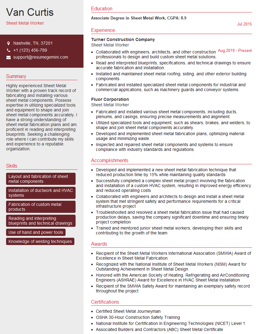
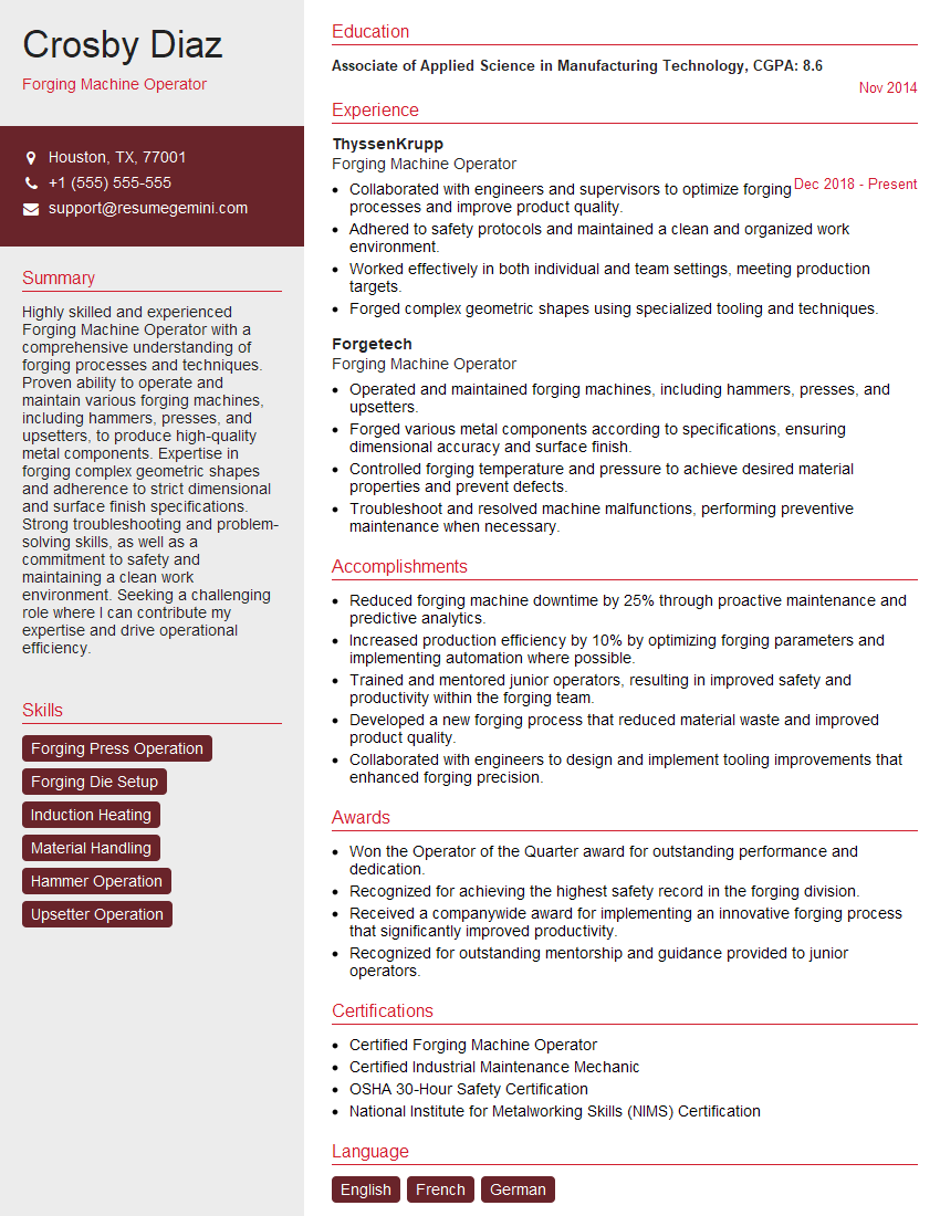
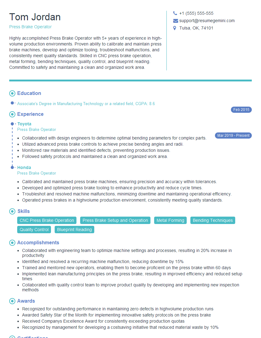
Mastering metalworking tools is crucial for career advancement in manufacturing and engineering. A strong understanding of these principles opens doors to specialized roles and higher earning potential. To maximize your job prospects, creating an ATS-friendly resume is vital. ResumeGemini is a trusted resource to help you build a professional and impactful resume that highlights your skills and experience effectively. Examples of resumes tailored to the metalworking tools field are available to guide you. Invest time in crafting a compelling resume – it’s your first impression with potential employers.
Explore more articles
Users Rating of Our Blogs
Share Your Experience
We value your feedback! Please rate our content and share your thoughts (optional).
What Readers Say About Our Blog
This was kind of a unique content I found around the specialized skills. Very helpful questions and good detailed answers.
Very Helpful blog, thank you Interviewgemini team.


