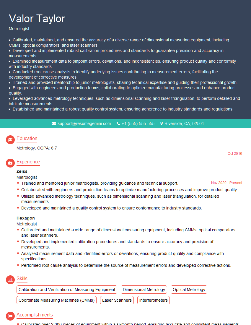
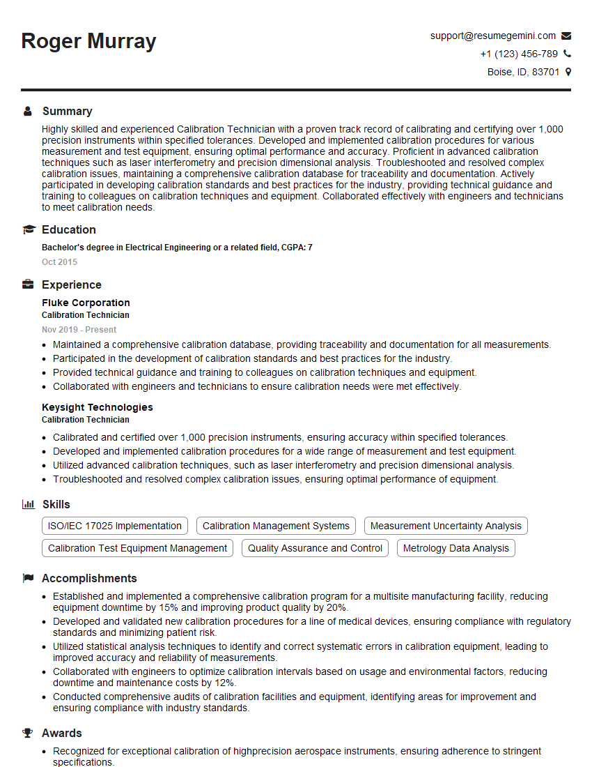
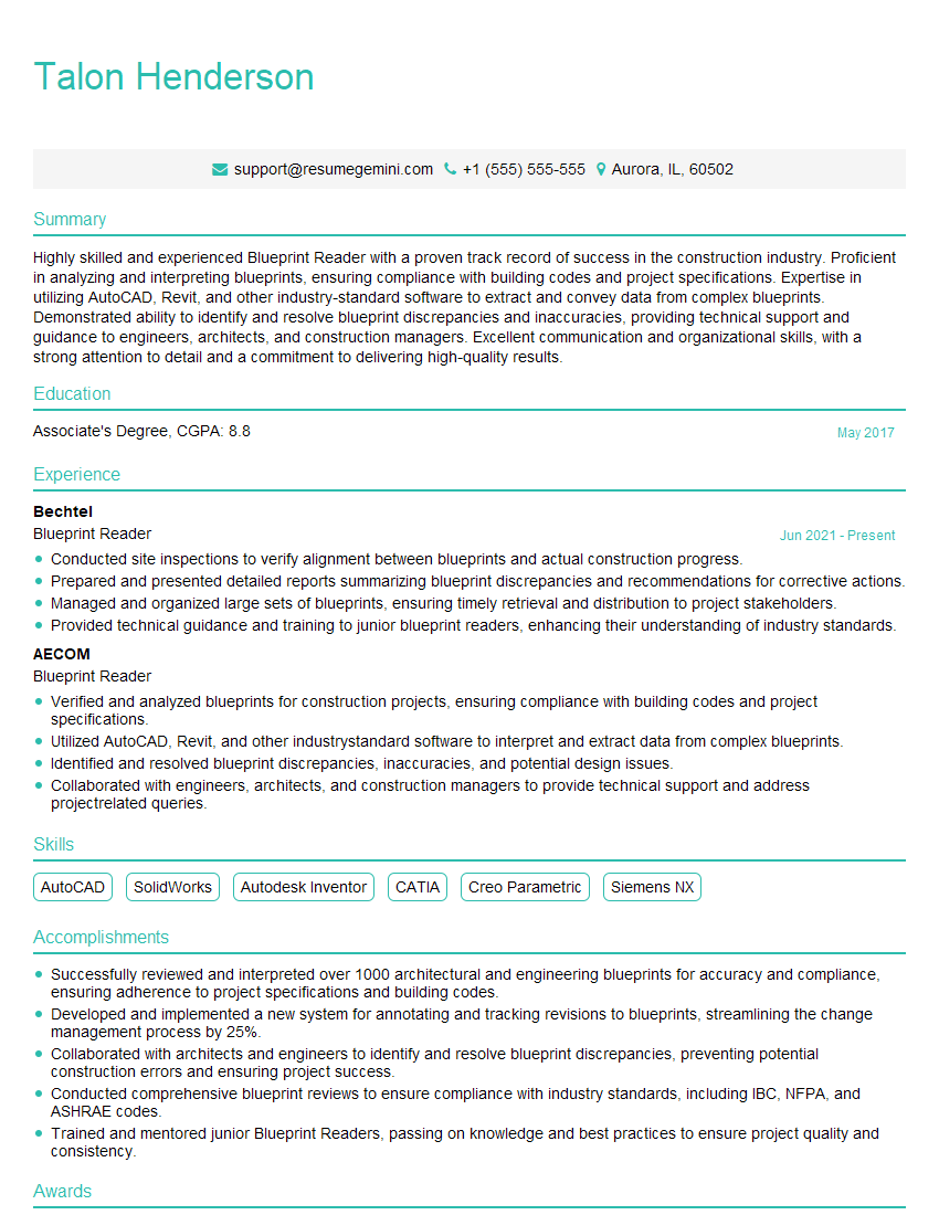
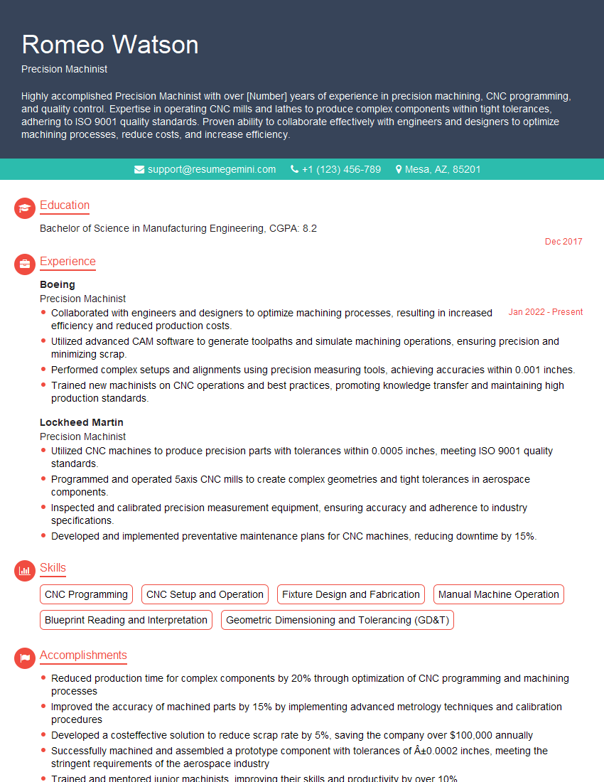
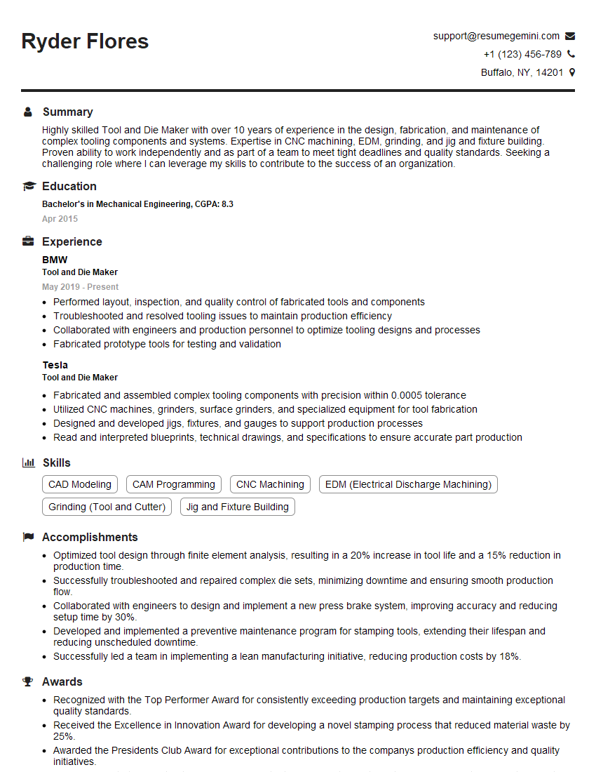
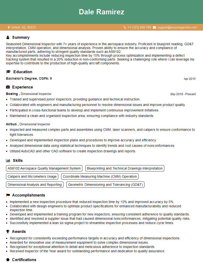
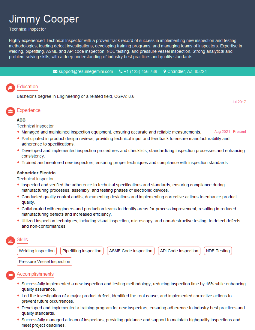
Interviews are opportunities to demonstrate your expertise, and this guide is here to help you shine. Explore the essential Precision Measuring and Layout interview questions that employers frequently ask, paired with strategies for crafting responses that set you apart from the competition.
Questions Asked in Precision Measuring and Layout Interview
Q 1. Explain the difference between accuracy and precision in measurement.
Accuracy and precision are often confused, but they represent distinct aspects of measurement quality. Accuracy refers to how close a measured value is to the true or accepted value. Think of it like aiming for the bullseye on a dartboard – high accuracy means your darts are clustered near the center. Precision, on the other hand, refers to how close repeated measurements are to each other. High precision means your darts are clustered tightly together, regardless of whether they’re near the bullseye. You can have high precision but low accuracy (all darts clustered tightly, but far from the bullseye), high accuracy but low precision (darts scattered around the bullseye), or ideally, both high accuracy and high precision.
For example, if the true length of a component is 10cm, a measurement of 10.01cm is more accurate than a measurement of 9.8cm. However, if multiple measurements yield values like 9.9cm, 10.1cm, and 9.8cm, the precision is low, even though the average might be close to the true value.
Q 2. What are the common sources of error in precision measurement?
Errors in precision measurement can stem from various sources, broadly categorized as systematic and random errors. Systematic errors are consistent and repeatable, often due to instrument calibration issues, environmental factors (temperature, humidity), or operator bias. For instance, a micrometer consistently reading 0.01mm too high introduces a systematic error. Random errors are unpredictable and vary from measurement to measurement, stemming from factors like vibration, human reaction time, or inherent limitations in instrument resolution. For example, slight variations in how a caliper is applied to a part can lead to random error.
- Instrument Calibration: Improperly calibrated instruments produce inaccurate readings.
- Environmental Factors: Temperature fluctuations, humidity, and even air currents can affect measurements, especially for delicate instruments.
- Operator Error: Incorrect handling, misreading scales, or parallax errors (viewing the scale at an angle) can introduce significant error.
- Part Geometry: Irregular part shapes or surface finish can complicate measurements and lead to inaccuracies.
- Wear and Tear: Over time, instruments can wear down, affecting their accuracy.
Q 3. Describe your experience with various measuring instruments (e.g., calipers, micrometers, CMM).
I have extensive experience using a variety of precision measuring instruments. My proficiency includes:
- Vernier Calipers: I’m adept at using vernier calipers to measure internal and external dimensions, depths, and steps with high precision. I understand how to minimize parallax error and ensure proper contact with the part.
- Micrometers: I’m experienced in utilizing micrometers for precise linear measurements, including inside, outside, and depth measurements. I understand the importance of proper thimble rotation and minimizing force to prevent deformation of the part.
- Coordinate Measuring Machines (CMMs): I have significant experience operating and programming CMMs, from basic point-to-point measurements to complex surface scans. I’m familiar with various probing systems and software packages, and I can develop measurement routines to meet specific inspection requirements. My experience includes CMMs from different manufacturers such as Zeiss and Hexagon.
- Optical Comparators: I am also comfortable using optical comparators for detailed inspection of parts and comparing them to master drawings.
In a recent project, I utilized a CMM to inspect a complex aerospace component, achieving measurement accuracy within ± 2 µm. This involved developing a custom measurement routine to compensate for the part’s intricate geometry.
Q 4. How do you interpret engineering drawings and blueprints?
Interpreting engineering drawings and blueprints requires a systematic approach. I start by understanding the drawing’s title block, which provides crucial information such as the drawing number, revision level, scale, and material specifications. I then systematically review the various views (orthographic projections, isometric views, etc.) to understand the part’s overall geometry and dimensions.
I pay close attention to:
- Dimensioning and Tolerancing: I meticulously check all dimensions, including their tolerances (allowable variations), to understand the acceptable range of variation. I’m familiar with various tolerancing standards (e.g., ASME Y14.5).
- Material Specifications: I verify the material used, as it influences the measurement process and the allowable tolerances.
- Surface Finish: I take note of surface finish specifications, as these affect the measurement techniques and instruments to be used.
- Notes and Annotations: I carefully read all notes and annotations to ensure a complete understanding of the design intent.
I often use software like CAD to aid in interpreting complex drawings and verifying measurements.
Q 5. Explain the process of setting up and using a Coordinate Measuring Machine (CMM).
Setting up and using a CMM involves several key steps:
- Machine Warm-up: Allow the CMM to warm up to ensure thermal stability, minimizing thermal drift and ensuring accurate measurements.
- Probe Calibration: Calibrate the probe using a standard artifact to verify its accuracy and compensate for any systematic errors. This usually involves measuring known dimensions on a calibration sphere.
- Part Setup: Securely mount the part on the CMM’s worktable, ensuring it’s stable and properly aligned to the machine’s coordinate system. This might involve using fixtures or specialized tooling depending on the part’s geometry.
- Program Creation/Selection: Depending on the complexity, either select a pre-existing measurement program or create a new one using CMM software. The program defines the points, surfaces, or features to be measured.
- Measurement Execution: Initiate the measurement program, ensuring the probe makes proper contact with the part at each designated point. This requires careful attention to detail and the ability to identify potential errors.
- Data Analysis: Review the measured data, compare it to the design specifications, and generate a report detailing the measurement results. This frequently includes identifying deviations and assessing whether they fall within acceptable tolerances.
Throughout the process, meticulous attention to detail, understanding of machine capabilities, and adhering to safety guidelines are paramount.
Q 6. How do you handle discrepancies between measured values and design specifications?
Discrepancies between measured values and design specifications require careful investigation. My approach involves:
- Verification of Measurements: Repeat the measurements to rule out random errors. Use different instruments or techniques if necessary to verify the results.
- Instrument Calibration Check: Ensure that the measuring instruments are properly calibrated. Any calibration errors should be corrected or accounted for.
- Analysis of Potential Sources of Error: Investigate systematic errors such as environmental factors (temperature, humidity), operator error, or part deformation.
- Comparison with Drawings and Specifications: Re-examine the engineering drawings and specifications to ensure a complete understanding of the design intent and tolerances.
- Documentation and Reporting: Document all findings, including the measured values, potential sources of error, and any corrective actions taken.
- Decision Making: Based on the analysis, decide whether the discrepancy is acceptable within the tolerances or requires corrective action.
If the discrepancy falls outside acceptable tolerances, I would initiate a root cause analysis to determine the source of the problem. This could involve modifying the manufacturing process, re-examining the design, or further investigation to identify any measurement biases.
Q 7. What are your preferred methods for documenting measurement results?
I use a combination of methods to document measurement results, focusing on clarity, traceability, and completeness. This typically includes:
- Measurement Reports: Detailed reports are generated, which include all measured values, statistical analysis (e.g., mean, standard deviation), and comparisons with design specifications. These reports are often created using CMM software or specialized metrology data management systems.
- Data Sheets: Simple data sheets are used for recording raw measurement data directly from instruments, including date, time, instrument identification, and operator identification.
- Digital Images and Videos: For complex parts or measurements, digital images and videos are used to document part orientation, measurement points, and overall part geometry. This provides a visual record for future reference.
- Database Management Systems: For large-scale projects or repeated measurements, a database system is used to organize and manage measurement data, allowing for easy retrieval and analysis.
All documentation adheres to company standards and relevant industry best practices to ensure accuracy and regulatory compliance.
Q 8. Describe your experience with statistical process control (SPC).
Statistical Process Control (SPC) is a powerful methodology used to monitor and control the variability in manufacturing processes. It relies on the use of control charts to track key process parameters over time. By analyzing data plotted on these charts, we can identify patterns and trends that indicate whether a process is in a state of statistical control (meaning the variation is inherent to the process and predictable) or out of control (indicating special causes of variation requiring attention).
In my experience, I’ve extensively used control charts like X-bar and R charts (for variable data) and p-charts and c-charts (for attribute data). For example, in a precision machining operation, I used X-bar and R charts to monitor the diameter of a crucial component. This allowed me to proactively identify shifts in the process before they resulted in unacceptable levels of scrap or rework. The early detection of an out-of-control signal, flagged by a point falling outside the control limits, allowed for a timely investigation and corrective actions, preventing costly errors downstream.
My experience also includes using SPC software to automate data collection, chart creation, and analysis, further enhancing efficiency and accuracy.
Q 9. How do you ensure the traceability of your measurements?
Traceability in measurement is critical for ensuring the reliability and validity of our findings. It involves establishing a clear chain of custody for all measuring instruments and data obtained. This chain begins with the calibration of our instruments to traceable standards, typically national or international standards maintained by accredited laboratories. Each calibration provides a certificate indicating the accuracy and uncertainty of the instrument at the time of calibration. We meticulously document all calibration events, including the date, instrument ID, results, and the name of the calibrating technician.
For individual measurements, we maintain detailed records. This typically includes the date and time of the measurement, the instrument used (with its unique ID), the operator who performed the measurement, and the specific method or procedure followed. This comprehensive documentation allows us to track the origin of each data point and verify its accuracy, crucial for resolving discrepancies or investigating potential errors.
Imagine this like a family tree for your measurements. Every measurement has its lineage traced back to a certified standard, ensuring confidence in the results.
Q 10. Explain your understanding of geometric dimensioning and tolerancing (GD&T).
Geometric Dimensioning and Tolerancing (GD&T) is a symbolic language used on engineering drawings to precisely define the size, form, orientation, location, and runout of features. It goes beyond simple plus/minus tolerances by explicitly defining the allowable variations in a part’s geometry. Understanding GD&T is essential for ensuring that parts meet their intended function and are interchangeable.
I’m proficient in interpreting and applying various GD&T symbols, including:
- Form tolerances: Straightness, flatness, circularity, cylindricity
- Orientation tolerances: Parallelism, perpendicularity, angularity
- Location tolerances: Position, concentricity, symmetry
- Runout tolerances: Circular runout, total runout
For instance, a GD&T callout specifying position tolerance on a hole ensures that the hole’s center is within a specified zone relative to a datum feature. This is more precise and informative than a simple diameter tolerance, which only considers the size of the hole but not its location. My experience includes using GD&T in the inspection of complex parts, enabling effective communication between design and manufacturing teams, and ensuring the production of high-quality, functional components.
Q 11. What is your experience with different types of measuring probes used with CMMs?
Coordinate Measuring Machines (CMMs) utilize various types of probes to acquire measurement data. The choice of probe depends on the specific application and the geometry of the part being measured. My experience encompasses the use of several probe types:
- Touch-trigger probes: These are the most common type, offering high accuracy and repeatability. They work by detecting contact between the probe stylus and the part surface. I have used both single-point and multiple-point touch-trigger probes, the latter allowing for faster data acquisition.
- Scanning probes: These probes continuously measure the surface profile as they move across the part. They are ideal for complex shapes and provide a high density of measurement points. I’ve used both optical and contact-type scanning probes, each with its own advantages and limitations.
- Laser probes: These are non-contact probes that measure distance using laser technology. They are particularly useful for delicate or fragile parts. I have used laser probes for surface roughness measurement and dimensional inspection of complex surfaces.
Choosing the right probe is critical for efficient and accurate measurement. For example, using a scanning probe on a part with sharp edges might lead to probe damage, while a touch-trigger probe might not be suitable for measuring complex curved surfaces efficiently.
Q 12. Describe a situation where you had to troubleshoot a measurement problem.
During the inspection of a precision-machined turbine blade, we encountered inconsistencies in the measurement of the airfoil profile using a CMM with a scanning probe. The measurements showed significant deviations from the CAD model, particularly in certain sections.
My troubleshooting approach involved a systematic investigation: First, I verified the CMM’s calibration and confirmed the probe’s proper functioning. Next, I examined the part’s surface finish for imperfections, such as scratches or burrs, which could interfere with the scanning process. I also checked the probe’s alignment and the stability of the CMM’s setup. After ruling out these factors, I discovered that the issue stemmed from insufficient probe compensation for stylus deflection. By adjusting the probe parameters and re-running the measurements, I obtained consistent and accurate data which matched the CAD model closely. This experience underscored the importance of understanding both the equipment and the potential sources of error in measurements.
Q 13. How do you maintain and calibrate measuring instruments?
Maintaining and calibrating measuring instruments is crucial for ensuring the accuracy and reliability of our measurements. We follow a rigorous schedule for calibration based on the instrument’s type, use frequency, and manufacturer’s recommendations. This schedule ensures traceability to national standards.
Our maintenance procedures include regular cleaning, inspection for damage, and lubrication (when applicable). For example, we clean optical instruments carefully using specialized cleaning solutions and lint-free cloths. CMMs are inspected for any signs of wear or damage to the axes, and the probe is regularly checked for proper functioning. Calibration is conducted by accredited laboratories or in-house metrologists using traceable standards. Calibration data is recorded and documented meticulously. Calibration certificates are kept for each instrument. We manage this through a calibration management system that helps us track calibration due dates and generate reports.
Q 14. What software are you proficient in for precision measurement data analysis?
I am proficient in several software packages for precision measurement data analysis. My expertise includes:
- CMM software: I’m experienced with various CMM software packages including PC-DMIS, Calypso, and PolyWorks. These are used for programming measurement routines, collecting data, and generating inspection reports.
- Statistical software: I’m proficient in using statistical software such as Minitab and JMP for statistical process control, data analysis, and creating control charts to monitor process capability and identify potential sources of variation.
- CAD software: Proficiency in CAD software (e.g., SolidWorks, AutoCAD) is vital for comparing measurement data with design specifications.
These software packages allow for comprehensive analysis of measurement data, facilitating efficient quality control and process improvement. For example, I have used PC-DMIS to program complex measurement routines on a CMM and analyzed the data using Minitab to determine process capability indices and identify areas for improvement in the manufacturing process.
Q 15. How familiar are you with laser tracking systems?
Laser tracking systems are incredibly precise metrology tools I’m very familiar with. They use a laser beam to measure the three-dimensional position and orientation of a target, often a retroreflector mounted on a workpiece. This allows for highly accurate measurements of large components or complex assemblies that are difficult to measure with conventional methods. Think of it like a highly sophisticated, non-contact ruler that works in three dimensions and can track movement in real-time.
My experience includes using these systems for tasks like machine verification, robot calibration, and large-scale component alignment. For example, I’ve used them to verify the accuracy of a large CNC milling machine by tracking the movement of the tool head at various points across its travel range. The data provided by the system enables identification and correction of any deviations, ensuring the machine operates within its specified tolerance.
Different systems vary in accuracy and range, depending on factors like the wavelength of the laser and the type of retroreflector employed. I am proficient in operating and interpreting data from various laser tracking systems from different manufacturers and have experience in selecting the appropriate system based on the specific application and required accuracy.
Career Expert Tips:
- Ace those interviews! Prepare effectively by reviewing the Top 50 Most Common Interview Questions on ResumeGemini.
- Navigate your job search with confidence! Explore a wide range of Career Tips on ResumeGemini. Learn about common challenges and recommendations to overcome them.
- Craft the perfect resume! Master the Art of Resume Writing with ResumeGemini’s guide. Showcase your unique qualifications and achievements effectively.
- Don’t miss out on holiday savings! Build your dream resume with ResumeGemini’s ATS optimized templates.
Q 16. Explain the concept of tolerance stacking.
Tolerance stacking, simply put, is the accumulation of individual tolerances in an assembly. Each component has a specified tolerance—the permissible variation from its ideal dimension. When these components are assembled, their individual tolerances add up, potentially leading to a larger overall variation than desired. Imagine building a tower out of LEGOs, each brick slightly off in size. The higher the tower, the greater the chance it becomes unstable due to the accumulated errors.
This is crucial in precision engineering because it directly impacts the final product’s functionality. For instance, if a component needs to fit precisely into a housing, even small tolerances in individual parts can lead to an unacceptable fit. To mitigate tolerance stacking, designers and manufacturers employ various strategies, such as tighter tolerances on critical components, statistical tolerance analysis (e.g., Monte Carlo simulations), and the use of more advanced manufacturing processes like precision machining.
During my work, I’ve often used statistical analysis to predict the cumulative effects of tolerance stacking and then implemented corrective actions to minimize risks like implementing tighter dimensional controls on specific parts.
Q 17. How do you ensure the proper alignment during layout procedures?
Ensuring proper alignment during layout procedures is paramount for precision. It’s the foundation for accurate machining, assembly, and overall product quality. The process involves using a variety of tools and techniques to establish reference points and ensure all components are oriented correctly relative to each other and to the datum (the reference point or surface).
This often starts with establishing a stable and accurate datum, usually using a surface plate or a precision machine base. From there, alignment is achieved through a combination of methods, including:
- Optical alignment: Using lasers, optical squares, and autocollimators to establish precise lines and angles.
- Mechanical alignment: Using dial indicators, alignment telescopes, and precision measuring tools to verify dimensions and parallelism.
- Coordinate Measuring Machines (CMMs): Employing CMMs for highly accurate three-dimensional measurements and verification of alignment.
For example, in aligning a complex machine assembly, we would first establish a datum on a surface plate, then use optical alignment tools to ensure that all major components are correctly oriented before final assembly. Regular checks throughout the process with dial indicators and other precision measuring instruments confirm alignment precision.
Q 18. Describe your experience with different layout methods (e.g., surface plate, optical alignment).
My experience spans various layout methods, each suited to different situations and accuracy requirements.
- Surface plate layouts: This is a fundamental technique involving a highly precise, flat surface (the surface plate) as a reference. Components are positioned and aligned on the plate using precision measuring tools like dial indicators and height gauges. This method is well-suited for smaller assemblies where direct measurement and adjustment are feasible.
- Optical alignment: This involves utilizing optical instruments such as lasers, autocollimators, and optical squares to establish reference lines and planes. This method is particularly useful for large assemblies or when highly accurate angular alignment is critical. I’ve used this in aligning large optical systems and machine tool components, ensuring precise angular relationships between elements.
- Laser trackers: As discussed earlier, laser tracking systems are invaluable for verifying alignment in large, complex systems, often exceeding the capabilities of surface plate and optical methods. Their non-contact nature allows for measurement of components even while they are in operation.
The choice of method depends heavily on the project’s scale, complexity, and required accuracy. I’m comfortable with all the aforementioned methods and can select the most suitable one based on the specific circumstances.
Q 19. How do you handle non-conformances during the inspection process?
Handling non-conformances during inspection requires a systematic and documented approach. My process begins with careful investigation to identify the root cause of the discrepancy. This involves reviewing the original design specifications, the manufacturing process, and the inspection procedures.
Once the root cause is identified, I document the findings, including photographic and measurement evidence. A corrective action plan is then developed and implemented to address the non-conformances. This might include reworking the affected components, adjusting the manufacturing process, or even revising the design specifications if necessary. Crucially, preventative measures are put in place to prevent similar non-conformances from occurring in the future. All steps are meticulously documented and reviewed to ensure effectiveness and compliance with quality standards.
For instance, if a component fails to meet its dimensional tolerance, I would investigate whether the issue stems from tool wear, incorrect machine settings, or an error in the design. Based on the findings, the appropriate action, be it machine recalibration or a design revision, is taken and recorded.
Q 20. What is your experience with different types of measuring standards?
I have experience with a wide range of measuring standards, both national and international. This includes:
- ISO standards: Proficient in ISO standards related to dimensional metrology, including those related to geometric dimensioning and tolerancing (GD&T).
- National standards (e.g., ANSI, ASME): Familiar with national standards relevant to specific applications and industries.
- Calibration standards: I have experience using and maintaining calibrated measuring equipment, ensuring traceability to national or international standards. This is critical for ensuring the accuracy of measurements.
Understanding these standards is essential for accurate measurements and consistent results. I regularly consult these standards to ensure that our measurement practices and procedures are compliant and that our data is reliable and defensible. For example, knowledge of GD&T is crucial for interpreting engineering drawings and ensuring that components meet the specified geometric requirements.
Q 21. Explain the importance of proper tooling and fixturing in precision measurement.
Proper tooling and fixturing are absolutely critical for precision measurement. They directly influence the accuracy, repeatability, and efficiency of the measurement process. Inadequate tooling or fixturing can lead to inaccurate measurements, damage to the workpiece, and increased measurement uncertainty.
Tooling refers to the specific tools used for measurement, such as micrometers, calipers, dial indicators, and CMM probes. The choice of tool depends on the measurement task and required accuracy. For instance, a high-precision micrometer would be used for extremely fine measurements, while a dial indicator might be better suited for measuring surface irregularities or runout. Proper calibration and maintenance of these tools are essential to maintain accuracy.
Fixturing refers to the devices used to hold and support the workpiece during measurement. A well-designed fixture ensures that the workpiece is stable and correctly oriented relative to the measuring tool. Poor fixturing can introduce errors due to workpiece deflection, vibration, or misalignment. I’ve encountered situations where a poorly designed fixture led to significant errors in measurement. Investing in robust and properly designed fixtures pays off in ensuring accurate and repeatable results.
Q 22. What are the safety procedures you follow while operating measuring equipment?
Safety is paramount in precision measurement. Before operating any equipment, I always begin by thoroughly reviewing the manufacturer’s safety instructions. This includes understanding the specific hazards associated with the instrument, such as laser safety for optical measuring systems or electrical hazards for electronic instruments.
I then ensure the workspace is properly organized and free of obstructions to prevent accidents. This involves wearing appropriate Personal Protective Equipment (PPE), such as safety glasses, gloves, and anti-static wrist straps where necessary. During operation, I maintain a focused and attentive state, avoiding distractions. If any malfunction or unusual behavior is detected, I immediately cease operation and report it to the appropriate supervisor.
For instance, when using a coordinate measuring machine (CMM), I always ensure the probe is properly calibrated and secured before initiating a measurement run. I regularly check for loose cables or potential tripping hazards around the machine. This methodical approach minimizes risks and ensures a safe working environment.
Q 23. Describe your experience with different types of material and their measurement considerations.
My experience encompasses a wide range of materials, each presenting unique measurement challenges. For instance, measuring the dimensions of a brittle ceramic component requires different techniques than measuring a flexible rubber gasket. With ceramics, I would prioritize non-contact measurement methods to avoid damage, potentially employing optical techniques like laser scanning. For rubber, I’d account for material deformation under pressure by using techniques like force-controlled probing or image analysis.
Metals require considerations of surface finish, which affects the accuracy of contact measurements. Rough surfaces can lead to inaccurate readings, necessitating careful probe selection or surface preparation. Similarly, the thermal properties of materials are crucial. Measuring a heated metal part would require compensating for thermal expansion to maintain accuracy.
Plastics can be prone to static electricity build-up, which can affect measurement precision, particularly with sensitive electronic instruments. Using anti-static measures is vital here. Each material requires a thoughtful approach to measurement selection and calibration, considering its unique physical and chemical properties.
Q 24. How familiar are you with the concepts of uncertainty and its propagation?
Understanding uncertainty and its propagation is fundamental to my work. Uncertainty refers to the doubt associated with a measured value. It’s not just about the instrument’s inherent precision, but also includes factors like environmental conditions (temperature, humidity), operator variations, and calibration uncertainties. Understanding these factors is critical for assigning a realistic confidence interval to our measurements.
Propagation of uncertainty involves calculating how uncertainties in individual measurements combine to affect the overall uncertainty of a derived quantity. For example, if I’m calculating the volume of a rectangular block from its length, width, and height measurements, each measurement will have its own uncertainty. The overall uncertainty of the calculated volume is determined by combining these individual uncertainties, using statistical methods.
In practice, I use software tools and established guidelines (e.g., ISO GUM, Guide to the Expression of Uncertainty in Measurement) to systematically analyze and quantify uncertainty, ensuring reported measurements are accompanied by a clear statement of their associated uncertainty.
Q 25. What is your experience with Root Cause Analysis techniques related to measurement issues?
I’m proficient in various Root Cause Analysis (RCA) techniques for resolving measurement issues. The ‘5 Whys’ method, for example, is a simple but effective tool for drilling down to the root cause of a problem. By repeatedly asking ‘why’ after encountering an issue, we systematically uncover underlying causes. For instance, if a CMM produces inconsistent measurements, the 5 Whys might reveal a faulty probe, a need for recalibration, or even an improperly leveled machine.
More complex RCA methodologies such as Fishbone diagrams (Ishikawa diagrams) or Failure Mode and Effects Analysis (FMEA) are utilized for more intricate situations involving multiple contributing factors. These methods help to identify potential failure points and prioritize corrective actions. Documenting these analyses is critical for preventing similar issues in the future, and improving our overall measurement processes.
In one instance, repeated inconsistent measurements from a particular CMM probe led to the discovery of a microscopic crack in the probe tip. This was only found after applying the 5 Whys method, ultimately leading to improved maintenance and inspection procedures.
Q 26. How do you manage your time effectively during a high-volume measurement task?
Managing time effectively during high-volume measurement tasks requires careful planning and prioritization. I start by thoroughly understanding the scope of the work, identifying any potential bottlenecks, and prioritizing tasks based on urgency and importance.
Batching similar measurements together and utilizing automated measurement systems, where appropriate, significantly increases efficiency. I also optimize my workflow to minimize instrument setup and changeover times. Lean principles are often implemented, focusing on eliminating waste and streamlining the entire process.
Furthermore, effective communication is crucial. Keeping my supervisor informed of progress, identifying potential delays early on, and collaborating with colleagues, avoids unexpected disruptions and keeps the project on track.
Q 27. Describe a situation where you had to work under pressure to meet a tight deadline.
During a critical project involving the inspection of thousands of aerospace components before shipment, we faced a severe time constraint. The original schedule was compromised due to unexpected equipment failure. To meet the strict deadline, I collaborated closely with the team to redesign the measurement process, prioritizing crucial checks and delegating tasks effectively.
We implemented a two-shift operation to maximize available time and used statistical sampling techniques to efficiently validate the quality of a representative sample of components. By streamlining the process and optimizing our efforts, we successfully met the deadline without compromising quality. This situation emphasized the importance of clear communication, adaptability, and collaborative problem-solving under pressure.
Q 28. What are your continuous improvement ideas for precision measurement processes?
Continuous improvement is essential for maintaining high levels of precision and efficiency in measurement processes. One key area for improvement involves investing in advanced measurement technologies like laser scanning or advanced CMM systems with automated probe recognition and data analysis capabilities. These technologies can significantly increase throughput and reduce the risk of human error.
Another important aspect is implementing robust statistical process control (SPC) methodologies to monitor measurement variability and promptly identify potential drifts or sources of error. Regular calibration and maintenance of equipment are also vital for consistent accuracy.
Finally, I believe continuous training and development for measurement personnel are crucial. Staying updated with new techniques and technologies ensures that the team consistently adheres to best practices and maintains high standards of measurement quality.
Key Topics to Learn for Precision Measuring and Layout Interview
- Understanding Measurement Systems: Mastering both metric and imperial systems, including conversions and tolerances. Practical application includes accurately interpreting blueprints and specifications.
- Precision Measuring Tools & Techniques: Develop expertise in using various tools like calipers, micrometers, dial indicators, levels, and laser measuring devices. Practical application involves demonstrating proficiency in accurate measurements within tight tolerances.
- Layout Techniques & Blueprint Reading: Thoroughly understand blueprint interpretation, including symbols, dimensions, tolerances, and annotations. Practical application includes accurately transferring design specifications onto materials for fabrication.
- Geometric Dimensioning and Tolerancing (GD&T): Gain a strong understanding of GD&T principles and symbols to ensure parts meet precise specifications. Practical application involves applying GD&T to assess part conformance.
- Problem-Solving and Troubleshooting: Develop skills to identify and resolve measurement discrepancies and layout errors. Practical application includes explaining how you approach and solve measurement challenges.
- Material Properties and their Impact on Measurement: Understanding how material properties like temperature and expansion affect accuracy. Practical application includes considering these factors in your measuring process.
- Safety Procedures and Best Practices: Familiarize yourself with safety protocols and best practices related to precision measuring and layout equipment. Practical application involves demonstrating a commitment to a safe working environment.
Next Steps
Mastering Precision Measuring and Layout is crucial for career advancement in many high-demand industries. These skills are highly valued for their precision and attention to detail, opening doors to rewarding opportunities and higher earning potential. To significantly increase your chances of landing your dream job, create a compelling resume that uses keywords effectively – a crucial factor for Applicant Tracking Systems (ATS). ResumeGemini is a trusted resource to help you build a professional and ATS-friendly resume. We provide examples of resumes tailored to Precision Measuring and Layout to guide you in showcasing your skills effectively. Take the next step in your career journey and build a resume that highlights your expertise!
Explore more articles
Users Rating of Our Blogs
Share Your Experience
We value your feedback! Please rate our content and share your thoughts (optional).
What Readers Say About Our Blog
This was kind of a unique content I found around the specialized skills. Very helpful questions and good detailed answers.
Very Helpful blog, thank you Interviewgemini team.
