The right preparation can turn an interview into an opportunity to showcase your expertise. This guide to Valve and Actuator Adjustment interview questions is your ultimate resource, providing key insights and tips to help you ace your responses and stand out as a top candidate.
Questions Asked in Valve and Actuator Adjustment Interview
Q 1. Explain the difference between pneumatic and electric actuators.
Pneumatic and electric actuators both provide the force needed to move a valve, but they achieve this in different ways. Think of it like this: a pneumatic actuator is like a powerful air-powered piston, while an electric actuator is like a precise, motor-driven mechanism.
Pneumatic Actuators: These use compressed air to generate the force. They’re robust, relatively inexpensive, and work well in harsh environments. However, they can be less precise than electric actuators and require an air compressor and associated piping infrastructure. An example would be a large gate valve on a pipeline controlled by a pneumatic actuator.
Electric Actuators: These use an electric motor to create the force needed for valve movement. They offer superior control, precision, and often allow for easier integration with control systems and automation. They might be more expensive upfront but offer better long-term efficiency and reduced maintenance in many cases. Imagine a smaller, precisely controlled valve in a chemical process, managed via a sophisticated PLC (Programmable Logic Controller) and driven by an electric actuator.
The choice between the two depends on factors like required precision, environmental conditions, cost, and the overall process control system.
Q 2. Describe the function of a control valve.
A control valve is like a gatekeeper for the flow of a fluid (liquid or gas) or even a finely ground solid within a process system. Its primary function is to regulate the flow rate, pressure, or temperature based on a control signal. This signal could come from a variety of sources, such as a sensor, a computer, or even a human operator. By precisely controlling the flow, it maintains the desired process parameters and optimizes efficiency and safety.
Think of a simple home heating system: a control valve in the boiler regulates the flow of hot water to the radiators, keeping your home at the temperature you set on your thermostat. This valve constantly adjusts its opening according to the need for more or less hot water.
Q 3. What are the common types of control valves?
There are many types of control valves, each designed for specific applications. Some of the most common include:
- Globe Valves: These are widely used and offer good flow control. They use a disc-shaped element to regulate the flow. They are suitable for a wide range of pressures and applications.
- Ball Valves: These offer on/off or quick-opening/closing functions, and are very simple to use. A spherical ball with a hole acts as an element that controls the flow.
- Butterfly Valves: These are known for their compact design and are used primarily for larger flows. A circular disc rotates to control flow, giving a high flow rate at the open position.
- Diaphragm Valves: These feature a flexible diaphragm that controls flow; they are often preferred in applications where leak-tight shutoff is crucial.
- Pinch Valves: These use a flexible sleeve to pinch or restrict the flow of fluid; they are well-suited for slurries or abrasive materials.
The selection of the appropriate valve depends heavily on the specific process, fluid characteristics, pressure, and required performance.
Q 4. How do you identify a faulty actuator?
Identifying a faulty actuator requires a systematic approach. You should start with visual inspection, looking for obvious signs of damage, leaks (in pneumatic actuators), or unusual wear. Listen for unusual noises such as grinding, squealing, or knocking. Then, you’ll need to check the actuator’s performance.
- Check for movement: Does the actuator move the valve stem smoothly and completely through its entire range of motion? Slow movement, sticking, or no movement at all indicate a problem.
- Verify the control signal: Ensure the actuator is receiving the correct control signal (e.g., from a PLC or control system). A faulty signal can prevent correct actuator operation. Use a multimeter to verify voltage or air pressure as appropriate.
- Inspect connections: Check all connections for tightness and proper operation. Loose or corroded connections can cause malfunctions.
- Monitor feedback signals: Many actuators provide feedback about their position or status. Examine these signals to identify discrepancies.
If the problem isn’t obvious, you may need specialized tools or expertise to diagnose more complex faults. For instance, you might need to test the motor windings in an electric actuator, or inspect seals and internal components in a pneumatic one.
Q 5. Explain the process of calibrating a valve actuator.
Calibrating a valve actuator ensures it responds accurately to the control signal, resulting in the desired valve position and process control. The exact procedure varies depending on the type of actuator (pneumatic or electric) and manufacturer, but the general steps are similar:
- Prepare the actuator: Isolate the actuator from the process, ensuring safety and preventing unwanted fluid flow during the calibration.
- Check the zero position: Determine the actuator’s full closed position (0%). This often involves manually adjusting the valve stem to its fully closed state and then setting this position in the actuator’s control system.
- Check the 100% position: Similarly, determine and set the actuator’s full open position (100%).
- Check intermediate positions: Many actuators allow for setting several intermediate positions (e.g., 25%, 50%, 75%). Verify the actuator achieves these positions accurately according to the control signal.
- Fine-tune the response: Using the actuator’s calibration tools (usually built-in or through dedicated software), fine-tune the actuator’s response to match the desired control signals.
- Document the calibration: Record the calibration settings and date, following your company’s procedures.
Calibration may involve specialized software and tools and should be done following the manufacturer’s instructions.
Q 6. What are the common causes of valve leakage?
Valve leakage can significantly impact process efficiency, safety, and environmental compliance. Common causes include:
- Worn or damaged seals: Seals wear over time, especially if exposed to harsh chemicals or high temperatures. This is a very common culprit.
- Improper valve packing: Inadequate packing or improperly packed glands prevent the stem from sealing correctly.
- Corrosion: Corrosion of valve components, particularly the stem and seat, creates gaps that allow leakage.
- Erosion: Erosion from high-velocity fluids can damage valve components.
- Misalignment: Improper valve alignment can prevent proper sealing.
- Foreign objects: Debris lodged in the valve can prevent proper sealing.
Regular inspection and maintenance of valves, including replacing worn seals and regularly lubricating moving parts, is key to minimizing leakage.
Q 7. How do you troubleshoot a stuck valve?
A stuck valve can be caused by many things, from simple mechanical issues to more serious problems. Troubleshooting requires a systematic process:
- Check for external obstructions: Examine the valve for physical blockages or obstructions that prevent movement. This might include pipes frozen due to low temperature, foreign bodies blocking the valve, or even excess buildup of residue.
- Check actuator power: Ensure the actuator receives power (electric) or air pressure (pneumatic) as needed. Use appropriate measuring tools to confirm this.
- Manual operation (with caution): Attempt to manually operate the valve stem to determine if the problem is with the actuator or the valve itself. Always follow safety procedures and lock out/tag out electrical and pneumatic lines before doing this.
- Inspect seals and internal components: If manual operation doesn’t work, the problem likely lies within the valve or actuator. Visual inspection might reveal worn or damaged components that need replacement.
- Check for binding: Look for any signs of binding or friction that might be preventing the valve from moving freely. This could be due to corrosion, material buildup, or a misalignment issue.
If you can’t identify and fix the problem, seek the assistance of a qualified technician. Never attempt repairs beyond your skill level.
Q 8. Describe different types of valve positioners.
Valve positioners are devices that enhance the accuracy and responsiveness of control valves. They improve performance by overcoming inherent limitations of pneumatic and electromechanical actuators. Different types exist, each suited to specific applications:
- Pneumatic Positioners: These are the most common type. They receive a control signal (typically 3-15 PSI) and use pneumatic power to precisely position the valve stem based on that signal. They offer simplicity, reliability, and a good balance of cost and performance. Think of them as a highly accurate amplifier for the pneumatic signal going to the actuator.
- Electro-pneumatic Positioners: These combine the precision of an electronic input signal with the power of a pneumatic actuator. The electronic signal is converted into a pneumatic signal that moves the valve stem. They offer increased precision, better control, and are often used in automated systems requiring accurate valve positioning.
- Smart Positioners: These incorporate advanced features such as digital communication protocols (e.g., FOUNDATION Fieldbus, Profibus), built-in diagnostics, and feedback mechanisms. They can provide real-time data on valve position, pressure, and other parameters, allowing for remote monitoring and improved troubleshooting. They’re ideal for complex control loops and remote monitoring applications.
- Hydraulic Positioners (Less Common): These use hydraulic pressure to position the valve. While offering high force capabilities, they are less common due to higher complexity and maintenance requirements compared to pneumatic systems.
The choice of positioner depends heavily on the application’s demands for accuracy, communication needs, and the type of actuator used. For instance, a smart positioner might be chosen for a critical process in a chemical plant, while a simpler pneumatic positioner might suffice for a less demanding application.
Q 9. What safety precautions should be taken when working with valves and actuators?
Safety is paramount when working with valves and actuators. Ignoring safety procedures can lead to serious injury or even fatality. Here’s a breakdown of essential precautions:
- Lockout/Tagout (LOTO): Always follow proper LOTO procedures before working on any valve or actuator. This prevents accidental activation during maintenance or repair.
- Personal Protective Equipment (PPE): Wear appropriate PPE, including safety glasses, gloves, and hearing protection, depending on the task. For high-pressure systems, specialized protective clothing might be necessary.
- Pressure Relief: Before working on any pressurized system, ensure that pressure is completely relieved and the system is isolated. Verify pressure using appropriate gauges.
- Confined Space Entry: If working in a confined space, follow all confined space entry procedures and ensure proper ventilation and respiratory protection.
- Understanding the System: Thoroughly understand the process and the operation of the valve and actuator before starting any work. Be aware of potential hazards associated with the fluid being handled.
- Proper Tools: Use the correct tools for the job to avoid damaging the equipment or causing injury.
- Emergency Procedures: Be familiar with emergency procedures and know where to find the nearest emergency shutdown switches and safety equipment.
For example, I once worked on a valve that had a hidden pressure release valve. Had I not carefully checked for secondary pressure sources, I could have been seriously injured during the maintenance procedure. Thoroughness and careful adherence to safety protocol are crucial.
Q 10. Explain the concept of valve characterization.
Valve characterization describes the relationship between the valve’s stem position and its flow rate. It’s crucial for accurate control system design and tuning. A valve’s flow characteristic can be linear, equal percentage, quick opening, or modified.
- Linear: Flow rate changes linearly with valve stem position. A 50% open valve allows 50% of the maximum flow.
- Equal Percentage: Flow increases by an equal percentage for each increment of stem travel. This provides better control at low flow rates.
- Quick Opening: Flow increases rapidly at the beginning of the stroke, and then more slowly as the valve opens further. Suitable for applications requiring rapid response.
- Modified Characteristics: These are customized combinations designed to meet specific application requirements.
Understanding the valve’s characteristic is vital for proper control. An improperly characterized valve can lead to poor control and even system instability. For instance, an equal percentage characteristic is preferred when a process requires precise control over a wide flow range, such as in a temperature control loop in a chemical reactor.
Q 11. How do you determine the correct sizing of a valve?
Correct valve sizing is essential for efficient and reliable operation. This involves determining the valve’s capacity to handle the required flow rate, pressure drop, and fluid properties. Several factors are considered:
- Fluid Properties: Viscosity, density, temperature, and other fluid characteristics significantly affect the valve’s sizing.
- Flow Rate: The maximum and minimum flow rates the valve needs to handle.
- Pressure Drop: The difference in pressure across the valve, which determines the required valve size.
- Valve Type: Different valve types (e.g., globe, ball, butterfly) have varying pressure drop characteristics.
- Valve Trim: The internal parts of the valve, which impact flow characteristics and pressure drop.
- Safety Factor: It is common practice to include a safety factor in sizing calculations to account for uncertainties and future demands.
Valve sizing is typically done using manufacturer’s selection tools or specialized software. These tools take into account all the relevant factors to calculate the appropriate valve size. Incorrect sizing can lead to excessive pressure drop, wear, and even valve failure. For example, undersizing a control valve in a steam line could lead to excessive erosion and premature failure.
Q 12. What is the purpose of a valve limit switch?
A valve limit switch is a mechanical device that detects the valve’s position and provides a signal to indicate whether it’s fully open, fully closed, or at an intermediate position. These switches are important for:
- Safety Interlocks: Preventing operation of downstream equipment unless the valve is in the correct position.
- Process Control: Providing feedback to the control system about the valve’s status.
- Diagnostics: Indicating valve malfunction such as valve sticking or binding.
- Automation: Integrating valve position into automated systems.
Imagine a scenario where a large tank needs to be filled with a chemical. A limit switch on the fill valve would signal when the tank is full, preventing an overflow. These switches are essential for both safety and reliable process control.
Q 13. Explain the different types of valve trims.
Valve trim refers to the internal components of a control valve that influence flow characteristics and pressure drop. Different trim types are designed for specific applications.
- Linear Trim: Produces linear flow characteristics.
- Equal Percentage Trim: Produces equal percentage flow characteristics.
- Quick Opening Trim: Produces quick opening flow characteristics.
- Caging Trim: Helps reduce erosion and cavitation in high-velocity flow applications.
- Multi-Stage Trim: Used for handling high pressure drops and minimizing cavitation.
The selection of valve trim is crucial for ensuring efficient and reliable operation. For instance, a valve controlling a high-pressure steam line might require a multi-stage trim to reduce cavitation and noise. Improper trim selection can lead to premature wear, reduced control accuracy, and even valve failure.
Q 14. How do you perform a valve stroke test?
A valve stroke test verifies the valve’s proper operation and measures its travel. It’s a critical part of routine maintenance and troubleshooting.
The procedure typically involves:
- Isolating the Valve: Isolate the valve from the process by closing the isolation valves upstream and downstream. Verify that the valve is isolated from pressure by using appropriate pressure gauges.
- Manually Operating the Valve: Manually open and close the valve, noting any unusual resistance or binding.
- Measuring Stroke Length: Using a measuring device (e.g., a ruler or dial indicator), measure the total stroke length of the valve. This is the distance the valve stem travels from fully closed to fully open.
- Documenting Results: Record the results and compare them to the manufacturer’s specifications.
- Checking for Leaks: Inspect the valve and packing for any leaks.
If the stroke test reveals any issues (e.g., less than full stroke, binding, or leaks), appropriate repairs or replacements might be required. Regular stroke testing helps prevent unexpected failures and ensure the safe and efficient operation of process valves.
Q 15. What are the common maintenance tasks for valves and actuators?
Regular maintenance of valves and actuators is crucial for ensuring operational efficiency, safety, and longevity. Think of it like servicing your car – preventative maintenance prevents costly repairs down the line. Common tasks include:
- Visual Inspection: Checking for leaks, corrosion, damage, and proper alignment. This is your first line of defense, often revealing problems before they escalate.
- Lubrication: Applying appropriate lubricants to moving parts reduces friction and wear, extending the life of the components. The type of lubricant depends on the actuator and valve materials. Using the wrong lubricant can be detrimental.
- Testing Actuator Function: Manually cycling the actuator through its full range of motion verifies proper operation and identifies binding or sticking. This is best done with the valve disconnected to isolate any issues.
- Checking Valve Stem Travel: Ensuring the valve stem moves smoothly and completely throughout its range prevents incomplete opening or closing. A restricted stem can lead to inefficient operation or even equipment damage.
- Cleaning: Removing dirt, debris, and contaminants prevents interference with moving parts and ensures proper sealing. A build-up of grime can be a significant factor in malfunctions.
- Calibration (where applicable): For actuators with positioners or feedback mechanisms, regular calibration ensures accurate positioning and control. A miscalibrated actuator can lead to inaccurate process control.
The frequency of these tasks varies depending on the application, environmental conditions, and the type of valve and actuator. A harsh environment, for instance, will necessitate more frequent maintenance.
Career Expert Tips:
- Ace those interviews! Prepare effectively by reviewing the Top 50 Most Common Interview Questions on ResumeGemini.
- Navigate your job search with confidence! Explore a wide range of Career Tips on ResumeGemini. Learn about common challenges and recommendations to overcome them.
- Craft the perfect resume! Master the Art of Resume Writing with ResumeGemini’s guide. Showcase your unique qualifications and achievements effectively.
- Don’t miss out on holiday savings! Build your dream resume with ResumeGemini’s ATS optimized templates.
Q 16. Describe the different types of valve actuators based on power source.
Valve actuators are classified primarily by their power source. The choice depends on the application’s requirements, including power availability, environmental factors, and the required level of control precision. Common types include:
- Pneumatic Actuators: These use compressed air as the power source. They are simple, robust, and relatively inexpensive. Think of how a car brake system uses air pressure – similar principles apply here. They are ideal for applications requiring fail-safe operation (e.g., emergency shutdowns).
- Electric Actuators: These use electric motors to provide the driving force. They offer precise control, easy integration with control systems, and a wide range of torque outputs. They are suitable for applications requiring precise positioning and automated control.
- Hydraulic Actuators: These use pressurized hydraulic fluid as the power source. They provide high torque outputs, making them suitable for large valves or applications requiring significant force. Think of a hydraulic jack – the same principle of high pressure creating significant force is used here. They are usually chosen when very high force is required.
- Manual Actuators: These are operated manually using a handwheel or lever. While simple and inexpensive, they are only suitable for infrequent operation and limited applications. They are used in simpler systems where automation isn’t required.
Each type has its own advantages and disadvantages, and the selection should be based on a careful consideration of the specific application.
Q 17. How do you diagnose problems with pneumatic valve actuators?
Diagnosing problems with pneumatic valve actuators involves a systematic approach. Imagine it like troubleshooting a car engine – you need to isolate the problem step by step. Here’s a typical approach:
- Check Air Supply: Verify sufficient air pressure and flow to the actuator. A low air pressure or a leak in the air line will significantly affect the actuator’s performance. Use a pressure gauge to check the pressure.
- Inspect Air Connections: Look for leaks or loose fittings in the pneumatic lines. A visual inspection will often pinpoint leaks. Leaks can be heard using a stethoscope for easier detection.
- Examine Actuator for Damage: Check for any physical damage, such as cracks, leaks, or loose parts. A damaged actuator needs immediate repair or replacement.
- Test the Air Cylinder: Manually check the movement of the piston within the air cylinder to determine if it is moving freely or binding. Binding indicates a problem in the cylinder.
- Check the Valve Positioner (if applicable): Verify the positioner is functioning correctly and receiving proper signals. Malfunctioning positioners need adjustments or replacement.
- Check for Air Traps or Filters: A clogged filter or air trap can prevent proper air flow to the actuator. Clean or replace filters as needed.
By following this methodical approach, you can usually pinpoint the cause of the problem and take the appropriate corrective action.
Q 18. Explain the importance of proper valve alignment.
Proper valve alignment is crucial for efficient and reliable operation. Think of it like fitting a key into a lock – incorrect alignment will prevent smooth and effective functioning. Misalignment can lead to:
- Premature Wear: Misalignment puts added stress on the valve stem and seals, leading to premature wear and potential leaks.
- Leakage: A misaligned valve may not properly seal, resulting in fluid or gas leakage. Leakage can impact efficiency and safety, especially in hazardous environments.
- Reduced Valve Life: Increased wear and tear due to misalignment shortens the operational life of the valve, leading to more frequent and costly replacements.
- Erratic Operation: Misalignment can cause erratic movement and incomplete opening or closing of the valve, affecting process control and product quality.
Therefore, ensuring proper alignment during installation and periodic inspection during maintenance is essential to maximize the valve’s life and performance.
Q 19. How do you troubleshoot an electric actuator that is not responding?
Troubleshooting a non-responsive electric actuator requires a systematic approach. It’s similar to troubleshooting a computer – we need to check the power supply, the wiring, the software, etc. Here’s a structured approach:
- Check Power Supply: Verify that power is reaching the actuator. Use a multimeter to check voltage at the actuator terminals. Often, a simple blown fuse is the culprit.
- Inspect Wiring and Connections: Look for loose wires, broken connections, or damaged wiring. Ensure all connections are secure. Any damage to the wiring must be promptly fixed.
- Test the Motor: If possible, test the motor separately to check for any internal issues. You can often get diagnostic information from the motor itself.
- Check Control Signals: Verify that the control system is sending the correct signals to the actuator. Use a multimeter to check for the expected control signals. Check the programming for any errors.
- Inspect Limit Switches (if applicable): Ensure the limit switches are functioning correctly and not preventing movement. If limit switches are blocking actuation, they may need to be reset or repaired.
- Check for Error Codes: Many modern actuators have built-in diagnostic capabilities and display error codes. Consult the actuator’s manual to understand the meaning of any displayed codes.
Remember to always follow safety procedures and disconnect power before making any physical checks.
Q 20. What are the different types of feedback mechanisms used in valve actuators?
Feedback mechanisms in valve actuators provide information about the actuator’s position, speed, and other parameters. This is crucial for accurate control and monitoring. Common types include:
- Position Feedback: This indicates the current position of the actuator. It could be provided by potentiometers, LVDTs (Linear Variable Differential Transformers), or encoders. These sensors measure the physical position of the valve stem.
- Limit Switches: These simple mechanical switches detect the actuator’s end positions (fully open or fully closed). They are frequently used as a safety mechanism and for simple control strategies.
- Proximity Sensors: These sensors detect the presence or absence of an object (e.g., the valve stem) without physical contact. This is valuable for avoiding wear and tear.
The choice of feedback mechanism depends on factors such as required accuracy, cost, environmental conditions, and the complexity of the control system. For instance, a simple on/off system may only require limit switches, whereas a complex control system may use a positioner with a potentiometer for precise control.
Q 21. Explain how to interpret a valve performance curve.
A valve performance curve shows the relationship between the actuator’s input signal (e.g., air pressure, electrical signal) and the valve’s output (e.g., flow rate, percentage of opening). It’s like a graph showing how hard you push the gas pedal (input) and how fast the car goes (output).
Understanding the curve is crucial for determining valve characteristics and ensuring proper operation. Key aspects include:
- Linearity: A perfectly linear curve means a proportional relationship between input and output. Deviations from linearity indicate non-linear valve behavior, which requires consideration in control strategies.
- Hysteresis: This refers to the difference in output for the same input signal when the input is increasing versus decreasing. Hysteresis can result in inaccurate positioning and control.
- Deadband: This is the range of input signal values where the output doesn’t change. A large deadband means the valve is insensitive to small changes in the input signal.
- Operating Range: This refers to the input and output ranges within which the valve operates effectively. Operating outside this range can damage the valve.
By analyzing the performance curve, you can identify potential problems like sticking, leakage, or calibration issues. For example, a large deadband could indicate a problem with the valve’s packing or stem seal.
Q 22. What is the role of a valve positioner in a control loop?
A valve positioner is essentially a small, intelligent device that enhances the performance of a control valve. Think of it as a precision tuner for your valve. In a control loop, the positioner receives a signal (usually 4-20mA) indicating the desired valve position from a controller (like a PLC or DCS). The positioner then compares this signal to the actual valve position, detected through various feedback mechanisms (e.g., a potentiometer or a feedback transducer). Any discrepancy between the desired and actual position is corrected by the positioner, which adjusts the actuator’s power accordingly to move the valve stem to the precise setpoint. This ensures tighter control, faster response times, and improved accuracy compared to a simple valve actuator alone. For example, imagine trying to precisely control the water flow in a shower using only a simple valve – difficult, right? A positioner helps achieve that precision.
Q 23. How do you handle a valve that is exhibiting excessive noise?
Excessive noise from a valve often indicates cavitation, flashing, or simply improper valve sizing. To troubleshoot this:
- Check for cavitation: Cavitation occurs when the pressure within the valve drops below the liquid’s vapor pressure, causing vapor bubbles to form and collapse violently, creating noise. This can be addressed by ensuring sufficient downstream pressure or by changing to a valve design better suited to prevent cavitation, like a control valve with a larger Cv (flow coefficient).
- Check for flashing: Flashing occurs in two-phase flows (liquid and vapor), leading to similar noisy vapor bubble formation. Lowering the upstream pressure or utilizing a valve with a special trim might help mitigate this.
- Assess valve sizing: Incorrectly sized valves lead to excessive pressure drops and turbulent flow, creating noise. Re-sizing the valve is often the solution. A proper sizing calculation ensures smooth operation.
- Inspect for mechanical issues: Loose parts, worn components, or binding in the valve stem can also create noise. A visual inspection and potential replacement of faulty parts might be necessary.
- Check actuator alignment: An improperly aligned actuator can exert uneven forces on the valve, leading to noise.
Addressing the root cause, rather than just masking the noise, is crucial for long-term reliability. Consider using vibration monitoring tools to pinpoint the precise location and source of the noise.
Q 24. Describe the process of replacing a valve actuator.
Replacing a valve actuator involves several steps, and safety should be the top priority. The process typically starts with:
- Isolation: Isolate the valve completely from the process line. This might involve closing upstream and downstream block valves and ensuring zero pressure is present in the valve line.
- Lockout/Tagout (LOTO): Implement a rigorous LOTO procedure to prevent accidental activation of the system.
- Disassembly: Remove the actuator from the valve. This often involves removing connecting bolts and carefully disconnecting any pneumatic or electric supply lines. Make sure to document the connections to ensure correct reassembly.
- Inspection: Inspect the valve stem for damage or wear. The valve itself should also be inspected to determine if additional servicing or replacement is required.
- Installation of new actuator: Mount the new actuator securely onto the valve, ensuring proper alignment and correct torque for fasteners. Note that there are different valve actuator types (electric, pneumatic, hydraulic) and hence the installation procedure may vary.
- Connection: Reconnect all the pneumatic or electrical supply lines according to the previous documentation. Ensure proper pressure and voltage.
- Testing: After reassembly, thoroughly test the valve’s functionality, including checking for leaks and proper operation across the full range of motion.
- Documentation: Document the maintenance activity, including the date, replaced parts, and any observations made during the process.
Always consult the manufacturer’s instructions for specific details on disassembly and reassembly procedures.
Q 25. What are the common types of valve failures?
Common valve failures include:
- Stem leakage: This can result from worn packing glands, damaged O-rings, or a damaged valve stem itself. Leakage can lead to product loss, safety hazards, and environmental damage.
- Body leakage: Leakage from the valve body itself is a more serious issue, often requiring valve replacement. This usually indicates a significant problem such as corrosion or a crack.
- Seating problems: The valve’s seating surfaces may wear or become damaged, resulting in poor sealing and leakage. Regular inspection and timely replacement of worn parts are important.
- Actuator malfunction: Actuators can fail due to mechanical wear, electrical failure (in electric actuators), or pneumatic issues (in pneumatic actuators). Regular lubrication, maintenance, and calibration are crucial for preventing these failures.
- Corrosion: Valves exposed to harsh chemicals or environments are prone to corrosion, which can weaken the valve body, stem, and internal components.
- Erosion: Abrasive materials in the process fluid can cause erosion of the valve’s internal surfaces, leading to leakage and failure.
The specific type of failure depends heavily on the valve’s application and the nature of the process fluid.
Q 26. How do you determine the root cause of a valve malfunction?
Determining the root cause of a valve malfunction requires a systematic approach:
- Gather information: Collect data on the failure, including symptoms, operational history, and environmental conditions. What was the valve doing before it failed? What type of fluid is it handling? What are the pressure and temperature conditions?
- Visual inspection: Carefully inspect the valve and actuator for obvious signs of damage, wear, or leakage. Look for obvious signs such as cracks, corrosion, or loose connections.
- Functional testing: Test the valve’s functionality to determine the extent of the malfunction. Does it open and close completely? Are there any leaks?
- Diagnostics (if applicable): Some valves and positioners have built-in diagnostics that can provide information about the failure. Check for any fault codes or diagnostic messages.
- Pressure testing: Pressure testing can be performed to identify leaks in the valve body or stem.
- Review maintenance history: Review past maintenance records to see if there is any evidence of prior issues or missed maintenance that may have contributed to the failure.
By carefully analyzing the gathered data, a root cause analysis (RCA) can be performed to pinpoint the exact reason for the malfunction. Root cause analyses are a standard practice for many companies to track failures.
Q 27. What is the importance of regularly scheduled maintenance for valves and actuators?
Regular scheduled maintenance is crucial for maximizing the lifespan, reliability, and safety of valves and actuators. Think of it as regular check-ups for your car – preventing small problems from becoming major ones. It involves:
- Visual inspection: Regularly inspect valves and actuators for signs of wear, corrosion, or damage.
- Lubrication: Lubricate moving parts to reduce friction and wear.
- Calibration: Periodically calibrate valve positioners to ensure accurate control.
- Leak checks: Regularly check for leaks in the valve body, stem, and packing glands.
- Functional testing: Test the valve’s functionality to ensure proper operation.
- Cleaning: Clean valves and actuators as needed to remove dirt and debris. For example, buildup of contaminants can lead to faulty operation.
By preventing minor issues from escalating, regular maintenance reduces the risk of costly failures, downtime, and safety incidents. A well-maintained valve system ensures reliable and efficient operation, directly impacting productivity and profitability.
Q 28. Explain the relationship between valve sizing, flow rate, and pressure drop.
Valve sizing, flow rate, and pressure drop are inextricably linked. The valve’s Cv (flow coefficient) is the key parameter here. Cv represents the flow capacity of the valve – it describes the gallons per minute (GPM) of water at 60°F that will flow through a fully open valve with a 1 psi pressure drop.
The relationship can be summarized by the following equation (simplified):
Q = Cv * √(ΔP)where:
- Q = Flow rate
- Cv = Valve flow coefficient
- ΔP = Pressure drop across the valve
This means:
- Larger Cv: A larger Cv valve will allow a higher flow rate for a given pressure drop, or the same flow rate with a lower pressure drop.
- Smaller Cv: A smaller Cv valve will result in a lower flow rate for a given pressure drop or a higher pressure drop for the same flow rate.
Proper valve sizing is crucial for efficient operation. Under-sizing leads to excessive pressure drop and energy loss, while over-sizing can lead to poor control and reduced responsiveness. Accurate process modeling and understanding of the fluid properties are necessary for correct valve sizing.
Key Topics to Learn for Valve and Actuator Adjustment Interview
- Valve Types and Characteristics: Understanding different valve types (ball, gate, globe, butterfly, etc.), their operating principles, and suitability for various applications. This includes knowing their limitations and potential failure points.
- Actuator Mechanisms: Familiarize yourself with various actuator types (pneumatic, electric, hydraulic), their power sources, control systems, and the relationship between actuator selection and valve performance. Consider factors like speed, torque, and safety.
- Calibration and Adjustment Techniques: Master the procedures for calibrating and adjusting valves and actuators to achieve precise control and optimal performance. Understand the importance of accurate measurements and documentation.
- Troubleshooting and Maintenance: Develop your skills in diagnosing common problems with valves and actuators, including leaks, malfunctions, and performance degradation. Learn about preventative maintenance strategies and best practices.
- Safety Procedures: Understand and adhere to all relevant safety protocols when working with valves and actuators, especially in high-pressure or hazardous environments. This includes lockout/tagout procedures and personal protective equipment (PPE).
- Instrumentation and Control Systems: Gain an understanding of how valves and actuators integrate with larger instrumentation and control systems. This includes understanding process control loops and signal transmission.
- Practical Application: Consider case studies involving real-world scenarios where valve and actuator adjustments were crucial for optimizing a process or resolving a problem. Be prepared to discuss your problem-solving approach.
Next Steps
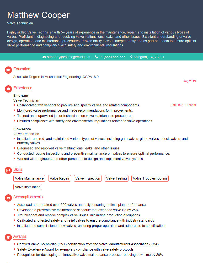
Mastering valve and actuator adjustment is crucial for a successful career in process control, automation, and related fields. It demonstrates a strong understanding of fundamental engineering principles and practical skills highly valued by employers. To significantly enhance your job prospects, it’s vital to create a resume that effectively showcases your skills and experience to Applicant Tracking Systems (ATS). We strongly encourage you to utilize ResumeGemini, a trusted resource for building professional and ATS-friendly resumes. ResumeGemini provides examples of resumes tailored to the Valve and Actuator Adjustment field to help guide you through the process. Take the next step towards securing your dream job today!
Explore more articles
Users Rating of Our Blogs
Share Your Experience
We value your feedback! Please rate our content and share your thoughts (optional).
What Readers Say About Our Blog
This was kind of a unique content I found around the specialized skills. Very helpful questions and good detailed answers.
Very Helpful blog, thank you Interviewgemini team.
