Every successful interview starts with knowing what to expect. In this blog, we’ll take you through the top Reading Blueprints and Diagrams interview questions, breaking them down with expert tips to help you deliver impactful answers. Step into your next interview fully prepared and ready to succeed.
Questions Asked in Reading Blueprints and Diagrams Interview
Q 1. What are the different types of lines used on blueprints and what do they represent?
Blueprints utilize various line types to convey different information. Think of them as a visual language for construction. Different line weights and styles represent different aspects of the design.
- Object Lines: Thick, solid lines define the outlines of objects and building components. They’re the ‘bones’ of the drawing, clearly showing the shape and size of things like walls, doors, and windows. For example, a thick, solid line would delineate the perimeter of a room.
- Hidden Lines: Thin, dashed lines indicate features that are not directly visible from the chosen viewpoint. Imagine you’re looking at a wall; hidden lines would show the placement of studs inside the wall that you can’t see.
- Center Lines: Thin, long and short dashed lines mark the center of symmetrical objects or features. They’re vital for accurate measurements and placement of symmetrical elements like doors or circular objects.
- Dimension Lines: Thin lines with arrowheads at each end indicate the distance between two points. They are essential for accurate construction and usually have the measurement value written above them. A common example is showing the length of a wall.
- Extension Lines: Thin lines extending from an object to the dimension line help to clearly show where the measurement originates and ends.
- Section Lines (Hatching): Consist of parallel lines used to indicate the material or cross section of an object. Different patterns may represent different materials (e.g., wood, concrete, steel).
- Break Lines: Short, zig-zag lines show a portion of an object that has been omitted from the drawing to save space, not implying a physical break.
Understanding these line types is crucial for accurately interpreting the blueprint’s information.
Q 2. Explain the significance of dimensions and tolerances on a blueprint.
Dimensions and tolerances are absolutely critical for accurate construction. They provide the exact measurements needed to build something correctly. Think of building a house of cards – you need precise measurements, or it’ll collapse!
Dimensions specify the size of elements – length, width, height, depth, diameter etc. They are typically shown using dimension lines, extension lines, and numerical values. For example, “10 ft” written above a dimension line indicates a 10-foot-long wall.
Tolerances represent the allowable variation from the specified dimension. It acknowledges that it’s impossible to achieve perfect precision. A tolerance might be expressed as ±1/16 inch, meaning the actual size can vary by 1/16 of an inch either way without affecting functionality or fit. Without tolerances, tiny errors during construction could accumulate, causing issues. They ensure components fit together and the overall structure is sound, even with minor variations in manufacturing or construction.
Q 3. How do you identify different materials on a blueprint?
Blueprints employ various methods to identify materials. Often, this is done through a combination of visual cues, symbols, and a materials legend.
- Fill Patterns (Hatching): Different patterns of lines within the object’s outline represent different materials. For example, closely spaced lines might indicate concrete, while a wood grain pattern would represent wood.
- Symbols: Standardized symbols represent materials. These can be referenced in a materials legend on the blueprint itself.
- Material Legend/Key: A table explaining each symbol or hatching pattern and the material it represents is usually included on the blueprint. This provides a clear reference for all materials used.
- Notes and Specifications: Textual notes accompanying sections of the drawings often specify materials. For example, a note might state “Steel Beam W12x14” indicating a specific type of steel beam.
Always check the blueprint for a materials legend or key, as it helps avoid misinterpretations.
Q 4. What are the common symbols used to represent electrical components on a blueprint?
Electrical components on blueprints use standardized symbols, so electricians worldwide can easily understand them. They’re like shorthand for electrical parts.
- Light Fixture: Usually a circle with radiating lines.
- Receptacle (Outlet): Often a circle with a short vertical line below it.
- Switch: Often a circle with a diagonal line through it.
- Circuit Breaker: Represented by a rectangular symbol.
- Motor: Shown with a circular symbol and other details to indicate type and specifications.
- Transformer: A rectangular symbol with a coil symbol inside.
It’s important to consult the electrical legend or symbols key on the blueprint for a precise meaning for each symbol as they may vary slightly depending on the standard followed.
Q 5. How do you interpret section views and detail drawings?
Section views and detail drawings provide detailed information about specific parts of a structure. They’re like zooming in on the blueprint for a closer look.
Section Views: These show an imaginary cut through an object to reveal its interior construction. They’re essential for understanding hidden details. Imagine slicing a cake – the section view would show the layers inside.
Detail Drawings: These are enlarged drawings focusing on a specific area or component. They give a magnified view of a complex area and highlight important details that might be too small or cluttered to see clearly on the main blueprint. They’re used to clarify aspects like joining methods or intricate elements.
Interpreting them requires careful attention to the cutting plane (indicated by a cutting line on the main drawing), symbols, dimensions, and materials used.
Q 6. How do you interpret a building’s elevation drawings?
Elevation drawings show the exterior appearance of a building from a single viewpoint, like a photograph. Imagine taking pictures of your house from each side – each photo would be an elevation drawing.
They usually show the height, width, and exterior features like windows, doors, and rooflines. They often include dimensions for building height, window placement, and other key aspects. This is essential for both understanding the exterior design and correctly constructing the building’s facade.
Multiple elevations (front, rear, sides) are typically provided to offer a comprehensive view of the building’s exterior.
Q 7. Explain the difference between isometric and orthographic drawings.
Isometric and orthographic drawings are both ways to represent 3D objects on a 2D surface, but they do so differently.
Orthographic Drawings: Use multiple views (front, top, side) to show the object completely. Each view shows the object from a perpendicular direction. Imagine using the instructions for assembling flat-pack furniture – the drawings typically use orthographic projections, showing you the individual pieces from multiple angles.
Isometric Drawings: Show a single view of the object, but it includes all three dimensions (height, width, depth) in a single drawing. It’s a perspective drawing, slightly angled, but not a true perspective like a photograph. Although useful for visualization, accurate measurements are more challenging to take from an isometric drawing than from an orthographic one.
In short, orthographic projections are more precise for measurements and construction, while isometric drawings offer a better visual representation for conceptual understanding.
Q 8. How do you determine the scale of a blueprint?
Determining the scale of a blueprint is crucial for accurate interpretation. Blueprints are scaled-down representations of a building or structure. The scale is usually indicated as a ratio, such as 1:100 or 1/4″=1′. This means that 1 unit on the blueprint represents 100 units in reality (in the first example), or 1/4 of an inch represents 1 foot (in the second).
To find the scale, look for a scale bar on the blueprint itself. This is a small line segment with markings indicating specific measurements. If a scale bar isn’t present, you might find the scale noted in the blueprint’s title block (a rectangular area usually found in a corner, containing project information). If neither is available, you may need to use known dimensions from the project to calculate the scale by comparing blueprint measurements to real-world dimensions.
Example: If a wall measures 10 feet long in reality and 1 inch long on the blueprint, the scale is 1 inch = 10 feet, or 1:120 (since 1 foot = 12 inches).
Q 9. Describe the process of interpreting a plumbing schematic.
Interpreting a plumbing schematic involves understanding its symbols and the flow of the plumbing system. These schematics usually use standardized symbols to represent fixtures (toilets, sinks, etc.), pipes, valves, and fittings. The schematic typically shows the layout of pipes, their sizes, and the direction of water flow.
The process starts with identifying the key components. Next, trace the flow of water from the source (usually a water main or well) to the fixtures and then to the drainage system. Pay close attention to pipe sizes, as these indicate the capacity of the system. Valves and fittings play a crucial role in controlling the flow and pressure of the water.
Example: A circle with a cross inside usually represents a valve. A thicker line would represent a larger diameter pipe. Following the lines, you can trace the water’s path and understand how the system functions.
Understanding the pressure and drainage aspects is critical. Checking for proper venting and slopes is important for a functional and safe system. Familiarity with various plumbing codes helps ensure the design meets safety regulations.
Q 10. Explain your experience working with CAD software to review blueprints.
I have extensive experience using CAD software (AutoCAD, Revit, etc.) to review blueprints. My proficiency includes navigating drawings, measuring distances, generating sections and elevations, and using various markup tools to highlight discrepancies or suggest changes.
In past projects, I utilized CAD software to overlay different drawings to identify conflicts between various trades (plumbing, electrical, HVAC). I’ve also used CAD to create 3D models from 2D blueprints to better visualize complex systems and detect potential issues before construction begins. My expertise also includes utilizing the software’s capabilities for creating detailed reports and documenting my findings. For instance, I can use the measurement tools to precisely quantify deviations from specifications and generate reports highlighting those findings.
Q 11. How do you identify potential conflicts or errors on a blueprint?
Identifying potential conflicts or errors on a blueprint requires a systematic approach and attention to detail. I typically start by reviewing the drawings for compliance with building codes and regulations. Then, I look for inconsistencies:
- Dimensional Conflicts: Checking for mismatched dimensions between different drawings (e.g., a wall shown at different lengths in the floor plan and elevation).
- Clash Detection: Identifying areas where different systems overlap or interfere (e.g., a duct running through a conduit).
- Code Violations: Ensuring the design meets all relevant building codes, accessibility standards, and fire safety regulations.
- Missing Information: Checking for gaps in specifications or missing details (e.g., unclear dimensions or missing material specifications).
- Symbol Inconsistencies: Identifying any discrepancies or unfamiliar symbols.
I often utilize layering and markup tools in CAD to highlight areas of concern. Detailed cross-referencing between various drawings is essential for a comprehensive review.
Q 12. How would you communicate a discrepancy found on a blueprint to your supervisor?
When communicating a discrepancy found on a blueprint, I prioritize clarity and professionalism. My approach involves preparing a concise and well-documented report, including:
- Clear Description: A detailed explanation of the identified discrepancy, using precise terminology and referencing the specific drawing and location.
- Visual Evidence: Including screenshots or marked-up drawings highlighting the issue. This is crucial for easy understanding.
- Proposed Solution: When possible, I suggest potential solutions to rectify the error, backed up by the relevant codes or standards.
- Impact Assessment: I briefly discuss the potential consequences of the discrepancy if left unaddressed.
I prefer a face-to-face meeting or video call, depending on the project’s logistics. This allows for immediate clarification and discussion. A written report, with attached documentation, will then be provided for permanent record. The communication style is always respectful and collaborative, aiming to find effective solutions rather than to place blame.
Q 13. Explain your experience reading and interpreting electrical schematics.
Reading and interpreting electrical schematics involves understanding the symbols and conventions used to represent electrical components and their interconnections. Electrical schematics differ from plumbing or architectural blueprints. They use standardized symbols to show circuits, power sources, loads (lights, appliances), and protective devices.
The interpretation process begins with identifying the power source (e.g., a transformer or a generator). Then, I trace the flow of electricity through the circuit, noting the components along the way. Understanding the voltage, amperage, and wiring methods is essential for determining the capacity and safety of the electrical system. I pay close attention to circuit breakers, fuses, and grounding connections, as these are crucial safety elements.
My experience includes reviewing schematics for various applications, from simple residential circuits to complex industrial systems. Understanding the National Electrical Code (NEC) is crucial for verifying the design’s compliance with safety regulations.
Q 14. How familiar are you with different types of construction documents?
I am very familiar with various types of construction documents. My experience encompasses a broad range, including:
- Architectural Drawings: Floor plans, elevations, sections, details, and schedules.
- Structural Drawings: Foundation plans, framing plans, and structural details.
- MEP Drawings (Mechanical, Electrical, Plumbing): Schematics and details for HVAC, electrical, and plumbing systems.
- Site Plans: Showing the location of the building on the site, including utilities and grading.
- Specifications: Detailed written descriptions of materials and construction methods.
- Shop Drawings: Detailed drawings prepared by subcontractors showing how specific components will be fabricated and installed.
I understand that each type of drawing serves a specific purpose and uses its own set of symbols and conventions. My ability to read and interpret these different documents effectively is paramount to my role in the construction process, ensuring efficient project delivery.
Q 15. How do you interpret structural details on a blueprint?
Interpreting structural details on a blueprint requires a systematic approach. First, I identify the relevant drawings – often sections and details – that show the structural elements. These typically include foundation plans, framing plans, and structural details showing connections and specifications.
I then look for key information such as:
- Foundation type and dimensions: Are we talking about a slab-on-grade, crawlspace, or basement? What are the exact dimensions and reinforcement details?
- Framing materials and methods: Is it wood framing, steel framing, or concrete? What are the sizes of the beams, columns, and joists? Are there specific bracing requirements?
- Connections and supports: How are the different structural elements connected? This often involves studying specific detail drawings to understand the methods used for beam-to-column connections, joist hangers, and other critical points.
- Load-bearing elements: Identifying which walls and components are load-bearing is crucial for avoiding structural damage during construction or renovations. I look for notations or symbols indicating load-bearing walls.
For example, a symbol might represent a specific type of concrete column, and a corresponding note would provide its size and reinforcement details. I then cross-reference this information with the structural calculations or engineering specifications to ensure everything aligns. I always carefully examine the symbols, scales, and notes on the drawings to avoid any misinterpretations.
Career Expert Tips:
- Ace those interviews! Prepare effectively by reviewing the Top 50 Most Common Interview Questions on ResumeGemini.
- Navigate your job search with confidence! Explore a wide range of Career Tips on ResumeGemini. Learn about common challenges and recommendations to overcome them.
- Craft the perfect resume! Master the Art of Resume Writing with ResumeGemini’s guide. Showcase your unique qualifications and achievements effectively.
- Don’t miss out on holiday savings! Build your dream resume with ResumeGemini’s ATS optimized templates.
Q 16. What is the importance of understanding the revision history of a blueprint?
Understanding the revision history of a blueprint is paramount to ensuring the accuracy and up-to-dateness of the construction documents. Revisions often occur to incorporate changes in design, client requests, or corrections found during the design process.
Ignoring revision history can lead to significant errors on-site, causing delays, rework, and potentially even safety hazards. A revision log, typically found on the blueprint sheets or in a separate document, details the changes made, the date of revision, and the person or team responsible. This allows me to trace back any changes and understand the rationale behind them.
For example, if a wall’s location has been altered in a later revision, understanding this change prevents me from constructing the wall according to an obsolete version of the drawing. I meticulously review the revision history before, during and after construction, making sure all teams are working from the same page.
Q 17. How do you ensure that you are reading the most up-to-date version of a blueprint?
Ensuring I’m using the most up-to-date blueprint version involves several steps. First, I always confirm with the project manager or architect what the latest revision number is. They will typically provide the most recent set of drawings. Then I confirm this with the digital file management system if available (like BIM software).
Furthermore, I check the revision cloud on the blueprints themselves. This cloud highlights areas where changes have been made. I also look for the revision stamps, which indicate the date, revision number, and a description of the changes.
Finally, I would compare the issue date of the construction drawings with the date of the structural calculation if they are available. Discrepancies would prompt me to seek clarification from the design team. A digital system with version control is the most effective way to guarantee working with the most updated version.
Q 18. Describe your experience in using blueprints to guide on-site construction work.
I have extensive experience using blueprints to guide on-site construction work. In previous projects, I’ve used blueprints to direct the layout of foundations, the installation of framing members, the location of utilities, and the placement of finishes.
One example involves a recent project where I was responsible for overseeing the construction of a multi-story building. Using the blueprints, I guided the team in setting out the foundation precisely, according to the surveyor’s markings and the foundation plan provided. We meticulously verified the dimensions, ensuring they adhered to the blueprint’s specifications.
Any discrepancies or questions were immediately addressed by referring to the relevant sections of the drawings and seeking clarification from the architect if necessary. This prevented costly errors and ensured the structural integrity of the building. Throughout the construction process, the blueprints served as a constant reference and verification tool. We used them to check materials, measurements, and installation techniques at every stage, ultimately ensuring a successful and compliant project.
Q 19. How familiar are you with building codes and how do they relate to blueprint interpretation?
I am very familiar with building codes and regulations. My understanding is crucial because these codes dictate the minimum acceptable standards for construction, encompassing structural integrity, fire safety, accessibility, and more. Blueprints must comply with these codes.
During blueprint interpretation, I actively check for compliance. I look for details that demonstrate adherence to code requirements, such as appropriate fire-resistant materials, proper accessibility features (e.g., ramp slopes), and sufficient structural capacity for anticipated loads.
For example, I would verify that the spacing of joists complies with the relevant code’s requirements for live and dead loads. If a blueprint shows a design that seems to violate a code, I immediately flag it for review by the architect or engineer. Failure to comply with building codes can result in project delays, fines, and even legal repercussions. My role is to ensure all construction aligns with the relevant codes and regulations.
Q 20. How do you interpret architectural details like door and window schedules?
Architectural details, such as door and window schedules, are crucial for accurate construction. These schedules provide a summarized list of all doors and windows in a building, along with their specifications. They act as a cross-reference to the floor plans and elevations.
Interpreting them involves understanding the nomenclature. For example, a typical entry might include a code like ‘WD-01,’ indicating a specific door type. The schedule would then detail the material (wood, steel, etc.), size, swing direction, and hardware requirements. Similarly, a window schedule lists various types of windows, their sizes, and locations, along with specifications such as glass type and frame material.
I use this information to verify that the correct doors and windows are ordered and installed in the designated locations. Discrepancies between the schedules and the floor plans are flagged and resolved before construction begins to prevent errors and ensure a consistent look throughout the building.
Q 21. Explain your approach to understanding complex multi-sheet blueprints.
My approach to understanding complex multi-sheet blueprints involves a methodical and organized strategy. I start by reviewing the index sheet to gain an overview of the entire project and identify the different drawings and their purpose. Then, I focus on the key drawings first: site plans, floor plans, elevations, and sections. These give a general understanding of the building’s layout and design.
After this initial overview, I systematically review the remaining sheets, paying close attention to the sheet numbers and cross-references. Detailed drawings, such as structural details, plumbing plans, and electrical plans, are reviewed in conjunction with the main drawings to understand the relationship between different building systems.
I use highlighting and annotations to mark important information, and create a summary sheet as needed, to track key details and ensure consistency across all drawings. Software tools like CAD can significantly aid this process. Understanding the project’s overall design intent and how different elements work together is critical. The methodical approach ensures comprehensive understanding and minimizes the risk of errors.
Q 22. How do you utilize blueprints to estimate material quantities?
Estimating material quantities from blueprints involves a systematic approach combining careful measurements and calculations. First, I identify the specific materials needed – concrete, lumber, drywall, etc. – from the blueprint’s specifications and details. Then, I carefully measure the dimensions of each component on the blueprint, using the provided scale. For example, if the blueprint indicates a wall is 10′ long and 8′ high, and the scale is 1/4″ = 1′, I would multiply 40 (10 x 4) by 32 (8 x 4) to get the actual dimensions in inches. This is crucial for calculating surface area. Next, I apply the necessary formulas to determine the volume or area required for each material. For instance, calculating the cubic yards of concrete for a foundation requires multiplying length, width, and depth. For drywall, calculating square footage would be appropriate. Finally, I add a contingency factor to account for waste, cuts, and unexpected issues, typically ranging from 5% to 15% depending on the material and complexity of the project. This ensures sufficient materials are ordered to complete the project smoothly.
Example: Let’s say a blueprint shows a concrete slab that’s 10′ x 12′ x 6″ deep. To calculate cubic yards, I’d convert inches to feet (6″ = 0.5′), then multiply: 10′ x 12′ x 0.5′ = 60 cubic feet. Since there are 27 cubic feet in a cubic yard, I’d divide 60/27 ≈ 2.2 cubic yards. Adding a 10% contingency, I would order approximately 2.4 cubic yards of concrete.
Q 23. How do you handle ambiguous or unclear information found on a blueprint?
Ambiguous or unclear information on a blueprint is a common challenge, requiring a methodical approach. My first step is to carefully review the entire blueprint, looking for related drawings or notes that might clarify the ambiguity. I often check for revision notes or addenda, as these can highlight corrections or clarifications. If the issue persists, I employ a multi-pronged strategy: I contact the architect or engineer responsible for the blueprint to seek clarification, meticulously documenting all queries and received responses. Simultaneously, I explore industry standards and best practices, consulting relevant codes and guidelines. If the discrepancy impacts structural integrity or safety, I would always err on the side of caution and adopt a conservative approach, documenting the decision-making process thoroughly. Finally, if the ambiguity cannot be resolved through these methods, I would flag it as a risk in the project documentation and seek alternative solutions or design adaptations.
Q 24. How do you collaborate with other professionals using shared blueprints?
Collaborating effectively on shared blueprints requires utilizing appropriate software and adopting clear communication protocols. I prefer cloud-based platforms like Bluebeam Revu or Autodesk BIM 360, which allow multiple users to access, annotate, and mark up the same blueprint concurrently. These platforms facilitate communication through comments and markups, minimizing confusion and ensuring everyone is working with the most up-to-date version. Before initiating any collaborative work, we establish a clear communication strategy, defining roles and responsibilities, setting deadlines, and choosing a primary point of contact for resolving ambiguities. Regular team meetings are crucial for discussing progress, addressing challenges, and ensuring everyone is aligned. Clear version control is paramount, using clearly labelled revisions and a change log to track modifications and avoid conflicts. This collaborative approach increases efficiency, enhances accuracy, and ensures all parties are on the same page.
Q 25. Explain your experience using blueprints in a project management context.
In project management, blueprints serve as the foundation for planning, scheduling, and resource allocation. I utilize blueprints during the initial planning phase to create detailed task breakdowns, accurately estimating timelines and material requirements. For example, by analyzing the blueprint, I can determine the sequence of construction tasks, identifying dependencies and critical paths. This is essential for creating a realistic project schedule and managing resources effectively. During the execution phase, blueprints are indispensable for guiding the construction team, ensuring that the work aligns with the design specifications. I use blueprints to track progress, identify potential issues early on, and make timely adjustments to the schedule or resource allocation if needed. By cross-referencing the as-built drawings with the original blueprints, I can ensure the final product matches the original design intent.
Example: In a recent project, detailed analysis of the plumbing blueprint allowed me to anticipate a potential conflict between the HVAC and plumbing systems. By proactively addressing this in the planning phase, we avoided costly rework and delays.
Q 26. What software and tools are you comfortable using to view and analyze blueprints?
I’m proficient in using various software and tools for viewing and analyzing blueprints. My go-to software includes Autodesk AutoCAD, Bluebeam Revu, and Revit. AutoCAD allows for precise measurements, detailed annotations, and the ability to create 3D models from 2D blueprints. Bluebeam Revu is excellent for collaborative markup and reviewing, ideal for team projects. Revit’s BIM capabilities help visualize the project in 3D, facilitating better understanding of spatial relationships. I also utilize industry standard PDF readers with measurement capabilities for basic analysis. Beyond software, I’m comfortable using physical tools such as scales, protractors, and drafting triangles for precise measurements and analysis when dealing with hard copies. The choice of tool depends on the complexity of the blueprint, the required level of analysis, and the project’s collaborative requirements.
Q 27. Describe a time you identified a critical error on a blueprint that prevented a costly mistake.
During a commercial building project, I noticed an inconsistency in the electrical blueprint. The plan showed a high-voltage line running directly beneath a proposed walkway. This oversight could have led to a serious safety hazard and significant rework. By identifying this error early during the design review, I alerted the electrical engineer. They confirmed my findings, re-designed the electrical layout, and successfully avoided the potentially catastrophic mistake. This saved the project considerable time and cost associated with rectifying the error during the construction phase, highlighting the importance of meticulous blueprint review.
Q 28. How would you explain a complex blueprint to someone without technical expertise?
Explaining a complex blueprint to a non-technical individual requires a patient and simplified approach. I begin by using relatable analogies. For instance, I might compare the blueprint to a detailed map of a house, explaining that different lines and symbols represent different elements, like walls, doors, and electrical wiring. I then guide them through the blueprint section by section, focusing on the key aspects relevant to their understanding. Instead of using technical jargon, I explain concepts using everyday language. Visual aids such as 3D models or simplified diagrams can be invaluable in enhancing understanding. Active listening and checking for comprehension at each stage are crucial to ensure they grasp the essential information. Finally, I provide a summary highlighting the main features of the design and answer any questions in simple terms, promoting clarity and engagement.
Key Topics to Learn for Reading Blueprints and Diagrams Interview
- Orthographic Projections: Understanding plan, elevation, and section views; interpreting multi-view drawings and identifying key features.
- Scale and Measurement: Accurately determining dimensions from blueprint drawings using different scales; applying this knowledge to real-world applications.
- Symbols and Conventions: Familiarizing yourself with industry-standard symbols and conventions used in blueprints and diagrams; recognizing different materials and construction methods.
- Isometric and Perspective Drawings: Interpreting three-dimensional representations of objects and spaces; understanding the relationship between 2D and 3D views.
- Sections and Details: Understanding the purpose of sectional views and detailed drawings; interpreting cross-sections to understand internal structures and components.
- Blueprint Reading Software: Familiarity with software used to create, edit and view blueprints, showcasing your ability to leverage technological tools.
- Practical Application: Discussing real-world scenarios where interpreting blueprints is crucial (e.g., construction, manufacturing, engineering). Be prepared to describe how you would approach problem-solving in these contexts.
- Troubleshooting and Error Detection: Demonstrating your ability to identify discrepancies or inconsistencies in blueprints and explaining how you would address them.
Next Steps
Mastering the ability to read and interpret blueprints and diagrams is paramount for career advancement in numerous technical fields. It demonstrates a crucial skillset for problem-solving, attention to detail, and understanding complex systems. To significantly boost your job prospects, invest time in crafting an ATS-friendly resume that highlights your proficiency. ResumeGemini is a trusted resource that can help you build a professional and impactful resume, showcasing your skills effectively. Examples of resumes tailored to showcasing expertise in Reading Blueprints and Diagrams are available within ResumeGemini to help guide you.
Facilities Manager Resume Sample
Construction Manager Resume Sample

Construction Superintendent Resume Sample
Project Coordinator Resume Sample

Project Engineer Resume Sample
Estimator Resume Sample
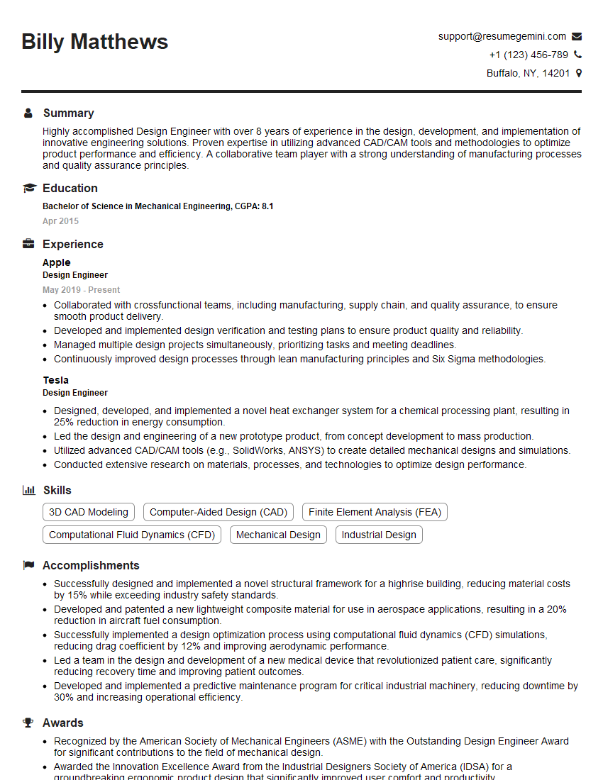
Design Engineer Resume Sample
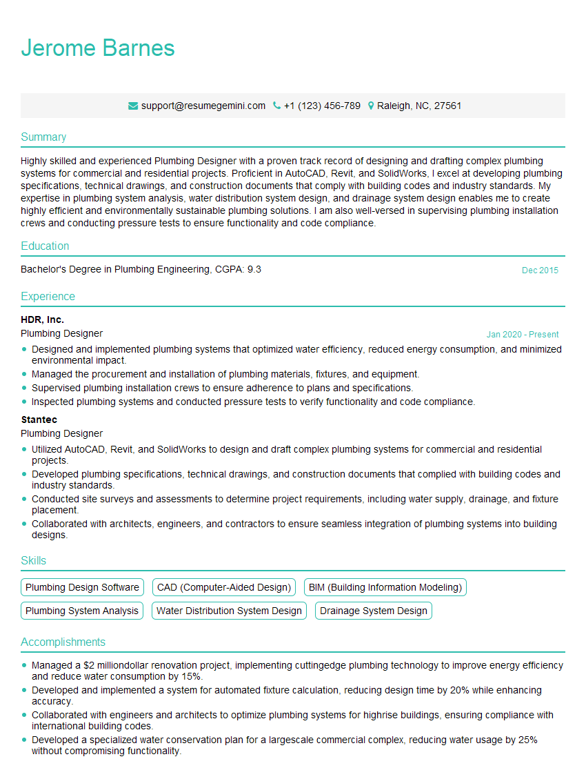
Plumbing Designer Resume Sample
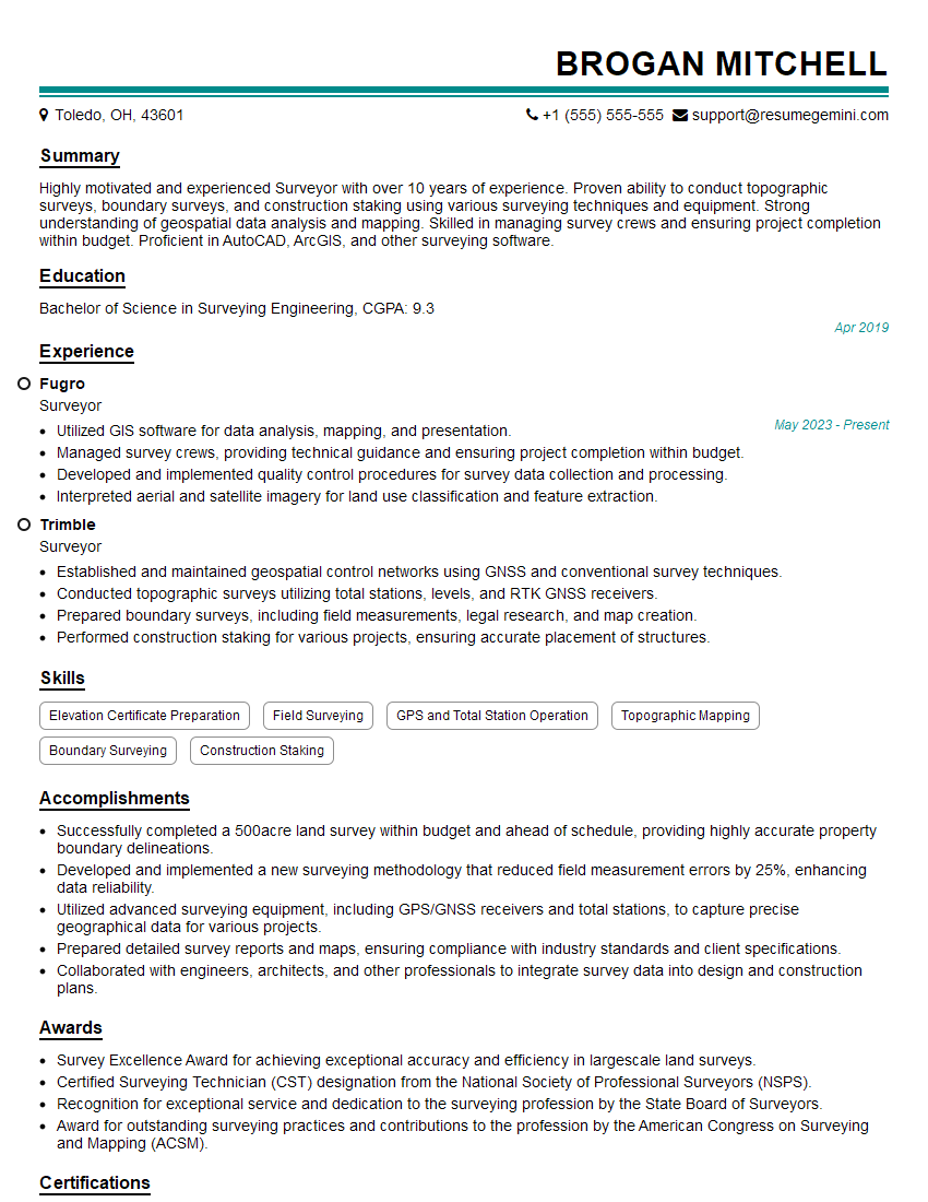
Surveyor Resume Sample

Engineering Technician Resume Sample

Civil Engineer Resume Sample
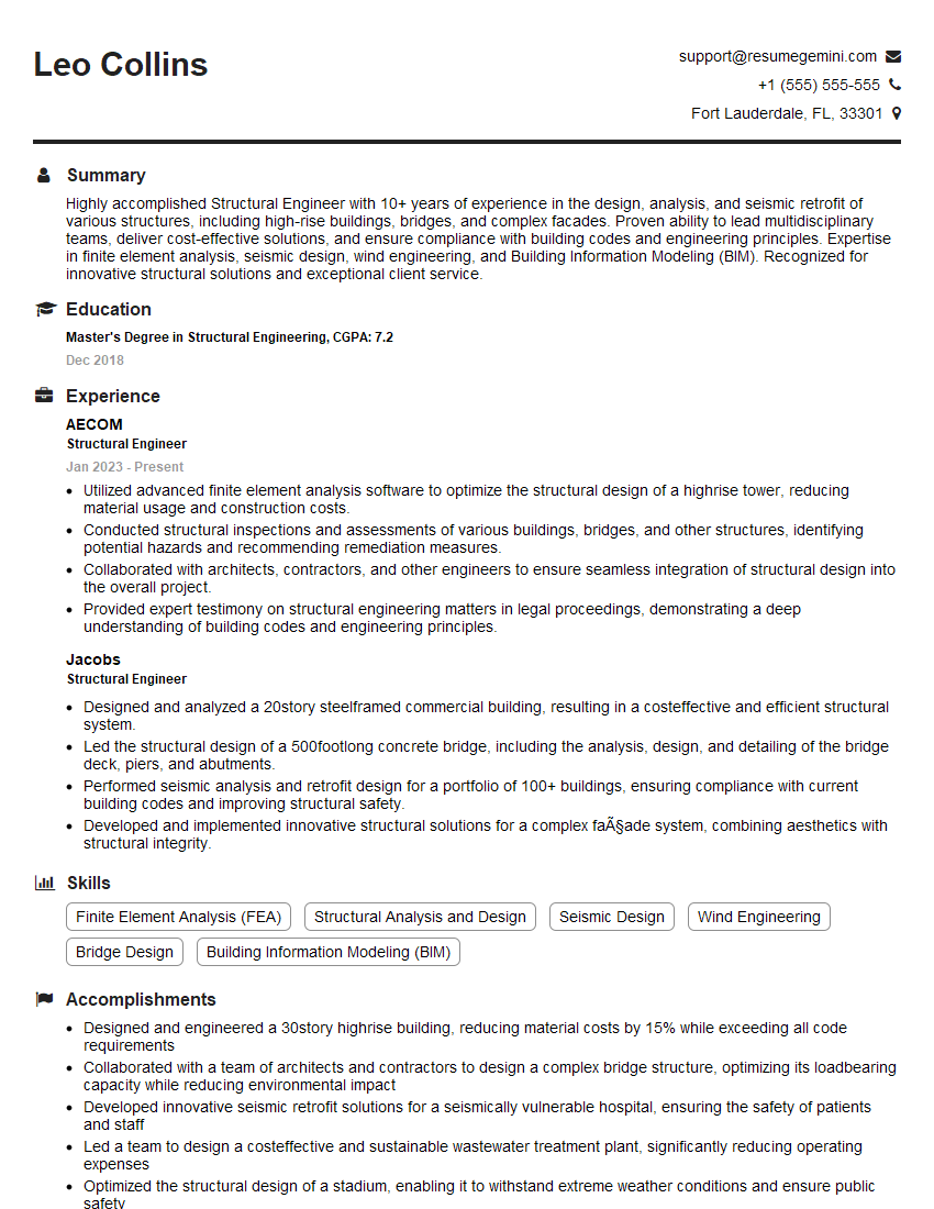
Structural Engineer Resume Sample
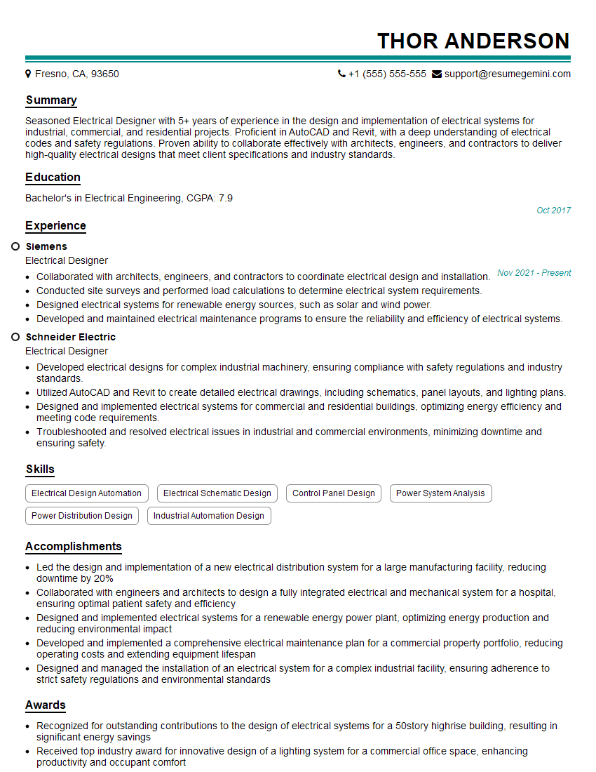
Electrical Designer Resume Sample

Electrical Engineer Resume Sample
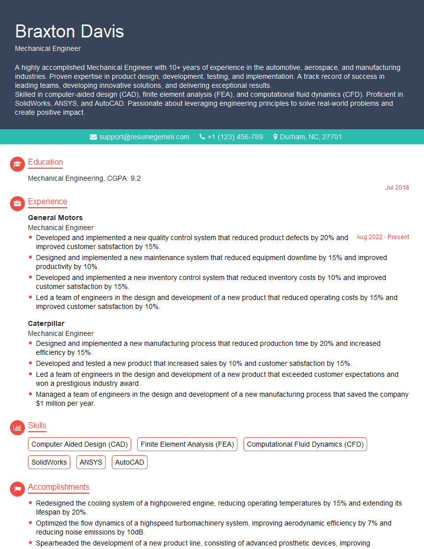
Mechanical Engineer Resume Sample
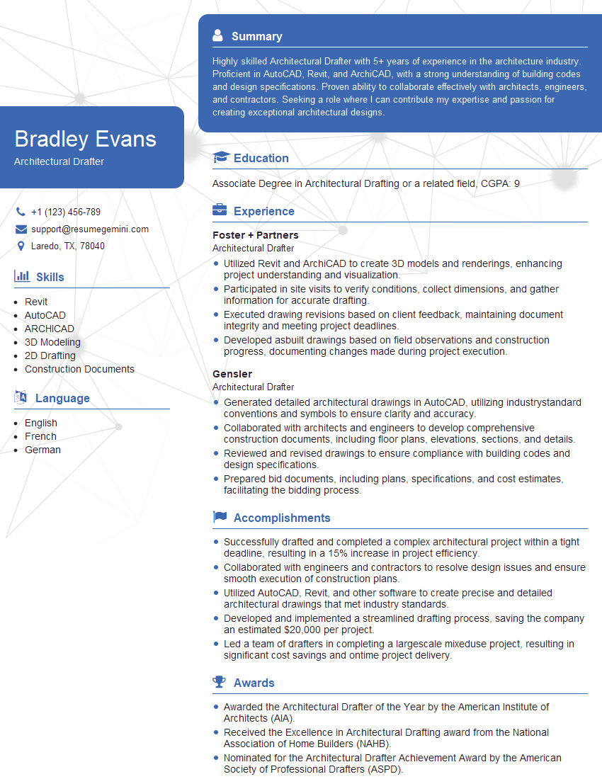
Architectural Drafter Resume Sample
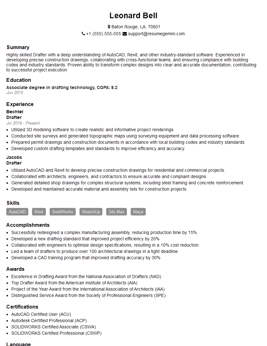
Drafter Resume Sample

Technical Designer Resume Sample
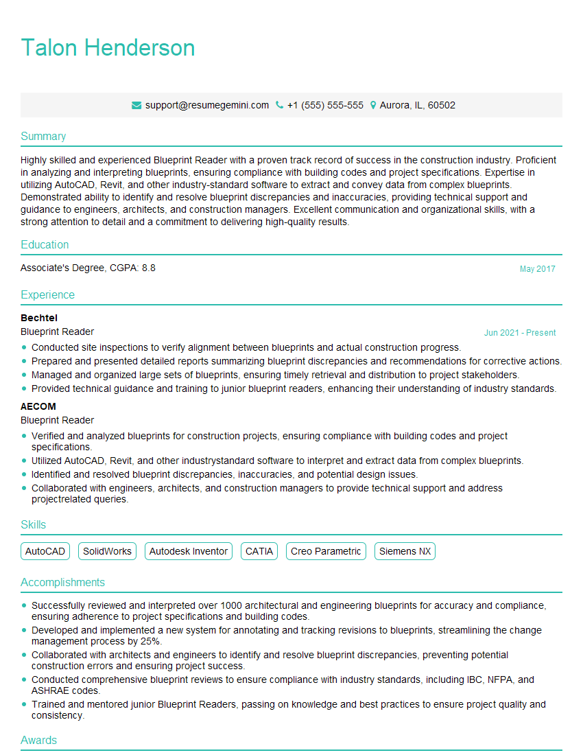
Blueprint Reader Resume Sample
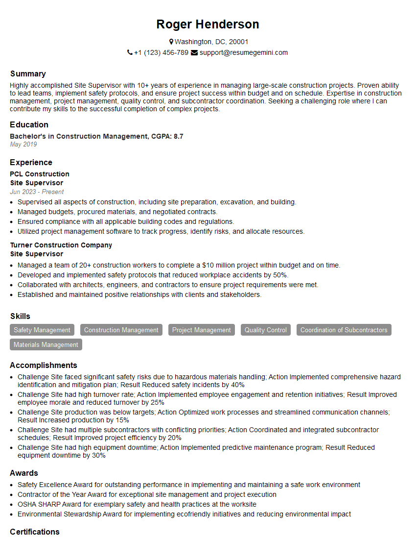
Site Supervisor Resume Sample

Quality Control Inspector Resume Sample
- Facilities Manager
- Construction Manager
- Construction Superintendent
- Project Coordinator
- Project Engineer
- Estimator
- Design Engineer
- Plumbing Designer
- Surveyor
- Engineering Technician
- Civil Engineer
- Structural Engineer
- Electrical Designer
- Electrical Engineer
- Mechanical Engineer
- Architectural Drafter
- Drafter
- Technical Designer
- Blueprint Reader
- Site Supervisor
- Quality Control Inspector
Explore more articles
Users Rating of Our Blogs
Share Your Experience
We value your feedback! Please rate our content and share your thoughts (optional).
What Readers Say About Our Blog
To the interviewgemini.com Webmaster.
Very helpful and content specific questions to help prepare me for my interview!
Thank you
To the interviewgemini.com Webmaster.
This was kind of a unique content I found around the specialized skills. Very helpful questions and good detailed answers.
Very Helpful blog, thank you Interviewgemini team.