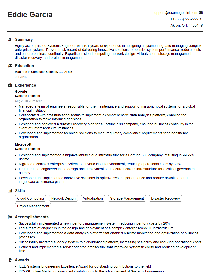
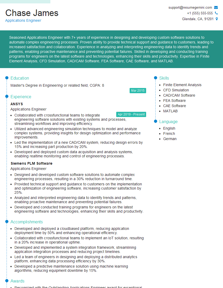
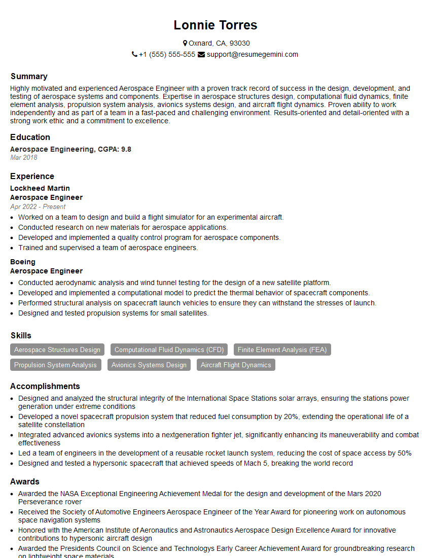
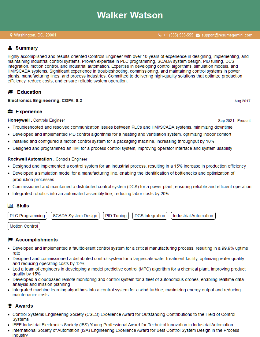
Interviews are more than just a Q&A session—they’re a chance to prove your worth. This blog dives into essential Electrical System Modeling and Simulation interview questions and expert tips to help you align your answers with what hiring managers are looking for. Start preparing to shine!
Questions Asked in Electrical System Modeling and Simulation Interview
Q 1. Explain the difference between continuous-time and discrete-time modeling.
The core difference between continuous-time and discrete-time modeling lies in how time is represented. Continuous-time models describe systems where variables change continuously over time, like the voltage across a capacitor. Discrete-time models, on the other hand, represent systems where variables are only defined at specific, discrete points in time, often as a result of sampling or digital control systems. Think of it like taking snapshots of a moving car – continuous-time is like watching a movie, capturing every moment; discrete-time is like looking at a series of still photos.
In mathematical terms, continuous-time models use differential equations to describe system dynamics (e.g., dv/dt = i/C for a capacitor), solved for any value of t. Discrete-time models use difference equations (e.g., v[k+1] = v[k] + i[k] * Δt / C, where Δt is the sampling interval), solved at specific time steps.
For instance, modeling the transient response of a power system following a fault requires continuous-time analysis due to the fast changes. In contrast, the operation of a digital protection relay that samples voltage and current at fixed intervals necessitates a discrete-time model.
Q 2. Describe your experience with different simulation software (e.g., MATLAB/Simulink, PSCAD, PSSE).
I’ve extensively used MATLAB/Simulink, PSCAD, and PSSE for various electrical system modeling and simulation projects. MATLAB/Simulink is my go-to for detailed control system design, dynamic analysis, and prototyping. Its extensive libraries for signal processing and control theory are invaluable. For instance, I’ve used it to model and simulate the performance of a power electronic converter controlling a distributed generation unit, employing detailed switching models and control algorithms.
PSCAD excels in simulating high-voltage power systems, especially for fault studies and transient stability analysis. I’ve leveraged PSCAD’s capabilities in a project to evaluate the impact of a large-scale wind farm on the stability of a regional transmission grid. The software’s sophisticated modeling capabilities and library of components made this analysis quite efficient.
PSSE is powerful for analyzing large-scale power systems under steady-state conditions, including load flow, short circuit, and optimal power flow studies. In a recent project, I used PSSE to analyze the impact of different renewable energy integration scenarios on the operational constraints of a national power grid. Its strength lies in efficiently handling massive datasets and performing system-wide analysis.
Q 3. How do you handle model complexity and computational limitations?
Handling model complexity and computational limitations requires a strategic approach. Firstly, model simplification is crucial. This might involve using reduced-order models, neglecting less significant components or phenomena, or employing equivalent circuits. Consider, for example, modeling a transformer. You could use a detailed model with multiple windings, saturation effects, and stray capacitances; however, a simpler equivalent circuit with just a few parameters might be sufficient for specific analyses.
Secondly, I utilize techniques such as parallelization and distributed computing to reduce simulation time. For large-scale simulations, breaking the model into smaller, manageable parts and running them concurrently significantly decreases the overall computation time.
Lastly, selecting an appropriate solver and simulation time step is also vital. A sophisticated solver might be necessary for solving complex, stiff equations accurately, but it would also come at a higher computational cost. Choosing the right time step involves balancing accuracy with computational efficiency.
Q 4. What are the common validation techniques for electrical system models?
Validation of electrical system models is crucial for ensuring accuracy and reliability. Common techniques include comparing simulation results against:
- Real-world measurements: This is the gold standard. Collecting data from real systems through monitoring or field tests provides benchmark data for model validation.
- Analytical solutions: For simplified cases, analytical solutions exist that can be compared to simulation results. This provides a way to assess model accuracy in a controlled setting.
- Benchmark models: Comparing the results with established benchmark models from literature or industry standards provides a quick verification.
- Independent simulations: Running the same model using different software or simulation approaches can help identify errors and improve confidence in the results.
The level of validation required depends on the application. For safety-critical applications, rigorous validation is mandatory, while less critical applications may require a more relaxed approach.
Q 5. Explain your understanding of model order reduction techniques.
Model order reduction (MOR) techniques are used to simplify complex models while retaining essential characteristics. This is particularly important for large-scale systems where computational resources are limited. The goal is to decrease the number of states and equations without sacrificing significant accuracy in the targeted frequency range.
Several MOR techniques exist, including:
- Krylov subspace methods: These methods project the high-order system onto a lower-dimensional Krylov subspace, preserving dominant dynamic characteristics.
- Balanced truncation: This technique identifies and removes less important states based on their contribution to the system’s input-output behavior.
- Singular perturbation methods: These methods separate the system into fast and slow subsystems, allowing the simplification of the fast dynamics.
The choice of MOR technique depends on the specific model and the desired level of accuracy. For instance, balanced truncation might be suitable for linear systems, while singular perturbation methods are better suited for systems with widely separated time scales.
Q 6. How do you ensure the accuracy and reliability of your simulation results?
Ensuring the accuracy and reliability of simulation results requires a multi-faceted approach. It starts with careful model development, ensuring that the model accurately represents the physical system being studied. This involves accurate parameter estimation, using reliable data and appropriate modeling techniques. Thorough validation, as discussed earlier, is essential.
Beyond validation, verification is crucial. This involves checking the simulation setup, ensuring the correct parameters and boundary conditions are used. It also involves verifying the accuracy of the numerical methods used by the software and checking for numerical stability and convergence.
Finally, a sensitivity analysis helps to understand the influence of uncertain parameters on the results. This provides insights into the robustness of the model and highlights areas where additional data or model refinement might be required.
Q 7. Describe your experience with different modeling techniques (e.g., state-space, transfer function).
I’m proficient in various modeling techniques. State-space representation is a powerful tool for modeling linear and non-linear dynamic systems. It describes the system using a set of first-order differential equations: ẋ = Ax + Bu, y = Cx + Du, where x is the state vector, u is the input vector, and y is the output vector. I often use state-space models for control design and analysis of power electronic converters and dynamic system stability studies.
Transfer function models are useful for linear time-invariant systems. They describe the relationship between the input and output using a ratio of polynomials in the Laplace domain. Transfer functions are convenient for analyzing frequency response and closed-loop system stability, often used for analyzing the behavior of filters and compensators in control systems.
Other modeling approaches I’ve utilized include impedance modeling for steady-state analysis of power systems, and detailed component models (e.g., synchronous machine models) for specific devices within the power system.
Q 8. How do you incorporate uncertainties and disturbances in your models?
Incorporating uncertainties and disturbances is crucial for creating realistic electrical system models. We can’t predict everything perfectly! Think of it like weather forecasting – you get a general idea, but there’s always some uncertainty. We handle this using several techniques:
Probabilistic Methods: Monte Carlo simulations are frequently employed. Here, we run the simulation many times, each with slightly different input parameters (e.g., load variations, component tolerances) drawn from probability distributions. The results give a statistical picture of the system’s behavior under uncertainty.
Stochastic Differential Equations (SDEs): These equations explicitly include random noise terms, modeling fluctuating elements like wind power generation or random load changes. The solutions then reflect the system’s behavior in the presence of these random disturbances.
Fuzzy Logic: If we have vague or imprecise information, fuzzy logic can help. For instance, if we only know a component’s resistance is ‘approximately’ 10 ohms, fuzzy logic can incorporate that uncertainty directly into the model.
For example, when simulating a power grid, we might use Monte Carlo to analyze the impact of uncertain renewable energy generation on voltage stability. Each run uses a different randomly generated renewable output profile.
Q 9. Explain the concept of Hardware-in-the-Loop (HIL) simulation.
Hardware-in-the-Loop (HIL) simulation is a powerful technique that bridges the gap between software simulation and real-world hardware. Imagine testing a car’s engine control unit (ECU) – you wouldn’t want to test it on a real car first, right? That’s where HIL comes in.
In HIL, a real-time simulator (typically a high-performance computer) models the rest of the system (e.g., the engine, transmission, and sensors) digitally. The ECU interacts with this simulated environment as if it were the actual physical system. This allows for comprehensive testing in a safe and controlled environment.
In electrical systems, HIL is used to test control systems for power electronics converters, microgrids, and even entire power systems. For instance, you could test a smart inverter’s response to a grid fault within a simulated power system before deploying it in the real world.
Q 10. What are the advantages and disadvantages of different simulation methods?
Various simulation methods exist, each with its own strengths and weaknesses:
Time-domain simulations (e.g., transient stability): These provide detailed information about the system’s response over time. They are computationally expensive, especially for large systems, but essential for understanding transient events like faults.
Frequency-domain simulations (e.g., harmonic analysis): These focus on the steady-state behavior of the system at various frequencies, offering insights into harmonic distortion and resonance. They’re computationally less demanding than time-domain methods.
Phasor-domain simulations: These use simplified phasor representations of voltages and currents, suitable for analyzing slower dynamics in power systems. They are computationally efficient for large systems.
State-space models: These represent the system using state variables and equations, useful for control system design and analysis. They provide a compact mathematical representation.
The choice depends on the specific application. For example, analyzing the impact of a lightning strike on a transmission line would require a time-domain simulation, while analyzing the steady-state harmonic distortion of a power electronic converter is best suited for frequency-domain simulation.
Q 11. How do you handle non-linear elements in your models?
Non-linear elements, such as transformers with saturation or diodes, present challenges in modeling. Linear models are simpler to analyze, but they don’t always reflect real-world behavior accurately. We address non-linearity using several techniques:
Piecewise Linearization: Approximating the non-linear characteristic with a series of linear segments. This simplifies the analysis while retaining some non-linear behavior.
Numerical Methods: Employing numerical methods like Euler’s method or Runge-Kutta methods to solve the differential equations directly. These methods can handle complex non-linearities but may require significant computational resources.
Iterative Methods: Using iterative solvers like Newton-Raphson to solve the non-linear equations. These methods require an initial guess and iteratively refine the solution until convergence.
For example, when modeling a transformer, we might use a piecewise linear approximation to represent the saturation curve. This allows us to capture the essential non-linear effects without resorting to highly computationally intensive methods.
Q 12. Describe your experience with real-time simulation.
My experience with real-time simulation spans various projects, including the development of a real-time digital simulator for a microgrid. This involved ensuring the simulation ran faster than the actual system dynamics – a critical aspect of real-time simulation. We used specialized hardware and optimized algorithms to achieve this. Challenges involved managing the computational demands of the complex microgrid model while maintaining accurate and stable simulation results. We incorporated hardware-in-the-loop capabilities to allow seamless integration with physical controllers and devices.
Another significant experience was working on a project simulating a large-scale power system. Meeting the real-time requirements for this project posed substantial challenges, especially given the sheer size and complexity of the system. We used parallel processing techniques and carefully selected simulation algorithms to address these challenges. This project highlighted the importance of rigorous validation and verification processes when working with real-time simulations.
Q 13. Explain your understanding of different types of power system simulations (e.g., transient stability, fault analysis).
Power system simulations are categorized based on the time scales and phenomena being analyzed:
Transient Stability Analysis: This examines the system’s response to large disturbances, such as faults, over a period of several seconds. It’s crucial for ensuring system stability after major events.
Small-Signal Stability Analysis: This investigates the system’s behavior under small perturbations and assesses its susceptibility to oscillations. It’s important for maintaining stable system operation under normal operating conditions.
Fault Analysis: This determines the current and voltage levels during fault conditions, critical for protection system design and coordination.
Harmonic Analysis: This focuses on the harmonic content of voltages and currents caused by nonlinear loads (e.g., power electronics converters), impacting equipment lifespan and performance.
Power Flow Analysis: This calculates the steady-state power flow throughout the system under normal operating conditions.
The type of simulation employed depends on the specific engineering problem. For example, designing a protection relay requires fault analysis, while planning for the integration of renewable energy sources often involves transient and small-signal stability studies.
Q 14. How do you choose the appropriate simulation software for a given project?
Selecting the right simulation software depends heavily on the project’s requirements and constraints. Several factors are crucial:
System Size and Complexity: For large systems, specialized power system simulation packages like PSS/E, PowerWorld Simulator, or DIgSILENT PowerFactory are often needed. These offer efficient algorithms for large-scale simulations.
Simulation Type: The choice depends on the type of analysis needed – time-domain, frequency-domain, etc. Some software excels in specific areas.
Modeling Capabilities: The software must support the specific components and models required for the system (e.g., detailed models of generators, transformers, transmission lines).
Budget and Licensing Costs: Open-source options like OpenDSS exist but might lack some features found in commercial software. Cost and licensing need careful consideration.
User Expertise and Support: Choose software that matches your team’s skills and has good documentation and support resources.
For example, a small-scale microgrid simulation might be suitable for MATLAB/Simulink, while a large-scale transmission system analysis would require a dedicated power system simulation package.
Q 15. Describe your experience with model calibration and parameter estimation.
Model calibration and parameter estimation are crucial steps in ensuring the accuracy and reliability of electrical system models. It involves adjusting the model’s parameters to match its behavior to real-world observations. This is like tuning a musical instrument – you adjust the various knobs (parameters) until the sound (model output) matches the desired melody (real-world data).
My approach typically involves a combination of techniques. I often start with least-squares estimation, where I minimize the difference between the model’s predicted outputs and the measured data. For more complex systems with non-linear behaviors, I employ advanced algorithms like particle swarm optimization or genetic algorithms to efficiently explore the parameter space and find the optimal set of parameters.
For example, in a recent project modeling a power transformer, I used a combination of least-squares and a genetic algorithm to estimate the parameters of an equivalent circuit model. The genetic algorithm was particularly effective in handling the non-linearity introduced by saturation effects in the transformer core.
Data quality plays a significant role. Inaccurate or noisy data can lead to inaccurate parameter estimations. Therefore, I always prioritize data validation and cleaning before starting the calibration process.
Career Expert Tips:
- Ace those interviews! Prepare effectively by reviewing the Top 50 Most Common Interview Questions on ResumeGemini.
- Navigate your job search with confidence! Explore a wide range of Career Tips on ResumeGemini. Learn about common challenges and recommendations to overcome them.
- Craft the perfect resume! Master the Art of Resume Writing with ResumeGemini’s guide. Showcase your unique qualifications and achievements effectively.
- Don’t miss out on holiday savings! Build your dream resume with ResumeGemini’s ATS optimized templates.
Q 16. How do you handle model verification and validation?
Model verification and validation (V&V) are essential to ensure the model accurately represents the real-world system. Verification confirms that the model is implemented correctly, while validation assesses how well the model predicts the system’s behavior. Think of it as building a house: Verification ensures that the blueprints are followed correctly during construction, while validation checks if the finished house meets the initial design specifications and functions as intended.
My V&V process typically involves:
- Verification: Code reviews, unit testing, and comparing simulation results with analytical solutions for simplified cases.
- Validation: Comparing simulation results with real-world experimental data. This might involve comparing transient responses, frequency responses, or steady-state operating points.
Statistical measures like RMSE (Root Mean Square Error) and R-squared are used to quantify the agreement between the model and real-world data. If discrepancies exist, I investigate potential causes, such as model simplifications, inaccurate parameters, or errors in the experimental data. Iterative refinement of the model, parameters and data may be necessary. A well-documented V&V process is crucial for building trust and confidence in the simulation results.
Q 17. Explain your experience with different types of controllers and their implementation in simulations.
I have extensive experience implementing various controllers in simulations, including:
- Proportional-Integral-Derivative (PID) controllers: These are widely used for their simplicity and effectiveness in controlling many systems. I’ve used them extensively in power system stability studies, regulating voltage and frequency.
- State-space controllers: These offer a more systematic approach, particularly for complex systems with multiple inputs and outputs. I’ve used them in designing optimal controllers for power electronic converters.
- Model Predictive Controllers (MPC): MPCs are particularly useful for systems with constraints, predicting future behavior and optimizing control actions accordingly. I’ve applied MPCs in optimizing power flow in smart grids.
Implementation involves defining the controller’s transfer function or state-space equations within the simulation environment. For example, implementing a PID controller might involve using a block diagram approach or writing custom code within the simulation software (e.g., using Simulink, PSCAD, or Python with libraries like Simpy).
% Example PID controller in MATLAB Kp = 10; Ki = 1; Kd = 0.1; controller = pid(Kp, Ki, Kd);
The choice of controller depends heavily on the specific application and performance requirements. Factors like robustness, computational complexity, and the need to handle constraints all influence the selection process.
Q 18. How do you address stability issues in your models?
Stability issues in electrical system models can arise from various sources, including incorrect parameter values, model simplifications, or the inherent instability of the system itself. Identifying and addressing these issues is crucial for obtaining meaningful simulation results.
My approach to handling stability problems involves a combination of techniques:
- Careful model development: Ensuring the model accurately represents the system’s dynamics is the first line of defense. This includes using appropriate models for components and considering all relevant interactions.
- Parameter sensitivity analysis: Assessing how sensitive the system’s stability is to changes in model parameters. This helps identify parameters that need to be accurately estimated.
- Eigenvalue analysis: Analyzing the system’s eigenvalues to determine its stability. Eigenvalues with positive real parts indicate instability.
- Control system design: Incorporating appropriate controllers to stabilize the system. This might involve using feedback control or other advanced control techniques.
- Numerical methods: Choosing appropriate numerical integration techniques to avoid numerical instability in the simulation.
For example, if a simulation becomes unstable due to a poorly tuned PID controller, I would adjust the controller gains or switch to a different control strategy. If instability arises from a modeling error, I would revisit the model and refine the components causing problems.
Q 19. What are the challenges you have faced during electrical system modeling and simulation projects?
Several challenges have emerged throughout my experience with electrical system modeling and simulation projects. One prominent challenge is the complexity of real-world systems. Simplifying a complex system for simulation inevitably involves compromises, and ensuring the simplification doesn’t overly distort the system’s behavior requires careful consideration and validation.
Another challenge is data availability and quality. Accurate and comprehensive data are essential for model calibration and validation, yet obtaining such data can be difficult and expensive. Data preprocessing and uncertainty quantification also require significant time and effort.
Furthermore, handling real-time constraints in simulations of dynamic systems, such as power grids, poses a significant hurdle. Efficient algorithms and computational resources are crucial for achieving satisfactory simulation speed while maintaining accuracy.
Finally, staying current with the rapidly advancing field of electrical systems requires continuous learning and adaptation. New technologies and modeling techniques regularly emerge, requiring ongoing professional development.
Q 20. How do you document and communicate your simulation results?
Effective documentation and communication of simulation results are essential for ensuring their value and impact. My approach involves several key aspects:
- Detailed reports: I prepare comprehensive reports that clearly describe the model, methodology, assumptions, and results. These reports include figures, tables, and statistical analysis to support the findings.
- Visualizations: Using clear and informative visualizations, such as graphs and diagrams, effectively communicates complex information. I utilize software like MATLAB and Python’s Matplotlib for creating high-quality visuals.
- Interactive tools: For complex results, I create interactive dashboards or web applications to allow stakeholders to explore the results in a user-friendly manner.
- Presentations: I deliver concise and engaging presentations tailored to the audience’s level of technical expertise, explaining the key findings and implications.
- Version control: Utilizing version control systems like Git helps track changes to models and scripts, facilitating collaboration and reproducibility.
Maintaining clear and accessible documentation not only ensures transparency but also facilitates future analysis and reuse of the simulation model and results.
Q 21. Explain your understanding of electromagnetic field modeling and simulation.
Electromagnetic field (EMF) modeling and simulation are crucial for analyzing and designing electrical systems, particularly at higher frequencies where the distributed nature of the fields becomes significant. It involves solving Maxwell’s equations to determine the distribution of electric and magnetic fields in a given geometry.
My understanding encompasses various techniques, including:
- Finite Element Method (FEM): This numerical method is commonly used for solving Maxwell’s equations in complex geometries. It involves dividing the geometry into smaller elements and solving the equations for each element. Software like COMSOL Multiphysics and ANSYS HFSS are widely used for FEM-based EMF simulations.
- Finite Difference Time Domain (FDTD): This time-domain method is effective for transient simulations. It discretizes both space and time and solves Maxwell’s equations iteratively. Software like Lumerical FDTD Solutions uses this method.
- Method of Moments (MoM): This integral equation method is suitable for analyzing structures with simple geometries. It solves for the surface currents induced on the structure by the incident electromagnetic field.
Applications range from designing high-frequency circuits and antennas to analyzing electromagnetic compatibility (EMC) and assessing the impact of electromagnetic interference (EMI).
For instance, in a recent project involving the design of a high-frequency power converter, I employed FEM to analyze the electromagnetic field distribution around the components and optimize the layout to minimize EMI.
Q 22. Describe your experience with thermal modeling and simulation.
Thermal modeling and simulation are crucial for predicting the temperature distribution and thermal performance of electrical systems. This is vital for ensuring reliability and preventing failures due to overheating. My experience encompasses developing and validating thermal models using various techniques, including finite element analysis (FEA) and lumped parameter methods. I’ve worked extensively with software packages like ANSYS and COMSOL Multiphysics to create accurate simulations. For instance, in a recent project involving the thermal design of a high-power electric motor, I used FEA to simulate the heat generation within the motor windings and the subsequent heat transfer to the cooling system. By analyzing the simulation results, I was able to optimize the cooling system design, reducing the motor’s operating temperature by 15°C and significantly improving its lifespan.
I also have experience with thermal network models, which are useful for simpler systems or faster simulations. These involve representing components with thermal resistances and capacitances, allowing for a more computationally efficient approach. For example, I used this technique to model the thermal behavior of a power electronics converter, enabling rapid exploration of different heatsink designs.
Q 23. How do you incorporate different physical phenomena (e.g., mechanical, thermal, electromagnetic) into your models?
Incorporating multiple physical phenomena into a single model requires a multiphysics approach. This is often necessary because electrical, mechanical, and thermal effects are strongly coupled in many electrical systems. For example, the current flowing through a conductor generates heat (Joule heating), influencing the conductor’s temperature and hence its electrical resistance. This resistance change, in turn, affects the current distribution and heat generation. To handle this, I frequently employ co-simulation techniques (discussed further in the next answer) or use specialized multiphysics solvers.
A common strategy involves using a staggered approach. This involves iteratively solving the governing equations for each physics domain, passing updated information between the solvers. For instance, a thermal solver will provide updated temperatures to the electromagnetic solver, which then updates the electrical characteristics. This iterative process continues until convergence is reached. Visualizing these interactions is crucial; I often use tools to visualize temperature distribution, stress analysis, and electromagnetic fields simultaneously. This allows for a comprehensive understanding of the system’s behavior under various operating conditions.
Q 24. Explain your experience with co-simulation techniques.
Co-simulation is a powerful technique that allows me to model complex systems by combining multiple specialized simulation tools. This is particularly useful when dealing with systems that involve interactions between different physical domains, each requiring a specific simulation approach. For instance, I might use a circuit simulator (like PSIM or MATLAB/Simulink) to model the electrical behavior of a power converter, and simultaneously use a mechanical dynamics simulator (like Adams) to model the mechanical stress on the converter’s components due to vibrations. The two simulations exchange data during runtime, allowing for a holistic and accurate representation of the system.
The key to successful co-simulation is selecting appropriate coupling strategies and managing data exchange effectively. I’ve worked with various coupling methods, including time-stepped coupling (where simulations exchange data at discrete time steps) and event-driven coupling (where data exchange is triggered by specific events in one of the simulations). A real-world application involved co-simulating a wind turbine’s control system (using Simulink) and the aerodynamic model of the turbine blades (using a CFD software). This allowed us to accurately predict the turbine’s performance and stability under varying wind conditions.
Q 25. Describe your experience with model-based design.
Model-based design (MBD) is a critical aspect of my workflow. It involves creating a mathematical model of a system early in the design process and using that model to simulate, analyze, and refine the system’s design. This allows for early detection and correction of potential problems, reducing development time and costs. My experience with MBD involves using tools like MATLAB/Simulink to build and simulate models of electrical systems.
I utilize MBD throughout the entire design lifecycle. Beginning with requirements analysis, creating a high-level model, gradually adding detail, verifying the model with experimental data, and finally deploying the model for control system design and testing. This iterative approach is key. For instance, in a recent project designing a battery management system (BMS), the MBD approach allowed us to test various control algorithms in simulation before implementing them on the physical system, resulting in improved performance and reduced testing time. This significantly reduced the risk associated with implementing the BMS into the final product.
Q 26. How do you ensure the scalability and maintainability of your models?
Scalability and maintainability are essential for any model. To ensure these, I employ a modular approach to model construction. I break down complex systems into smaller, manageable modules, each representing a specific component or subsystem. This allows for easier modification and expansion of the model. For example, a model of a power grid can be broken down into modules for individual generators, transmission lines, and loads. This modularity simplifies debugging and allows for selective refinement or replacement of individual modules without affecting the entire model.
Furthermore, I use version control systems (like Git) to track changes to the models and ensure collaboration amongst team members. Clear documentation, using comments within the model code and external documentation, is also crucial for maintainability. The use of standardized modeling practices and naming conventions enhances both scalability and maintainability across different projects and teams.
Q 27. Describe your experience with analyzing simulation results and drawing meaningful conclusions.
Analyzing simulation results involves more than just looking at graphs and numbers. It requires a systematic approach to extract meaningful insights. I typically begin by visualizing the simulation data using various plots and animations to identify trends and patterns. Then, I perform quantitative analysis to extract key performance indicators (KPIs), such as efficiency, temperature rise, and harmonic distortion. Statistical methods are also employed to quantify uncertainties and sensitivities.
I use these analyses to validate my models against experimental data, ensuring accuracy and reliability. Discrepancies between simulation and experiment are thoroughly investigated, leading to model refinement or highlighting potential issues in the experimental setup. Finally, I prepare comprehensive reports that clearly communicate the simulation results and their implications, using clear visualizations and concise language. A recent example involves analyzing the simulation results of a high-voltage direct current (HVDC) transmission system, identifying bottlenecks and suggesting improvements to the system’s design. This process ensures the findings are communicated clearly to a wide audience, maximizing impact and fostering collaboration.
Key Topics to Learn for Electrical System Modeling and Simulation Interview
- Power System Analysis: Understanding fundamental concepts like load flow studies, fault analysis, and stability analysis is crucial. Be prepared to discuss different solution methods and their applications.
- Transmission and Distribution Systems: Familiarize yourself with modeling techniques for overhead lines, cables, transformers, and protective devices. Be ready to discuss practical challenges and solutions in these areas.
- Renewable Energy Integration: Understand the modeling of various renewable energy sources (solar, wind, etc.) and their impact on power system operation. Discuss grid integration challenges and mitigation strategies.
- Control Systems and Automation: Gain a strong understanding of control system design and implementation within electrical systems. Be prepared to discuss topics such as state-space representation and control strategies.
- Simulation Software Proficiency: Demonstrate your experience with industry-standard simulation software like PSS/E, PowerWorld Simulator, or MATLAB/Simulink. Highlight your skills in model building, analysis, and interpretation of results.
- Practical Problem Solving: Practice solving real-world problems related to power system design, operation, and control. Focus on your analytical skills and ability to apply theoretical knowledge to practical situations.
- Advanced Topics (depending on the role): Depending on the specific job description, you might also consider delving into areas such as FACTS devices, power electronics, or smart grid technologies.
Next Steps
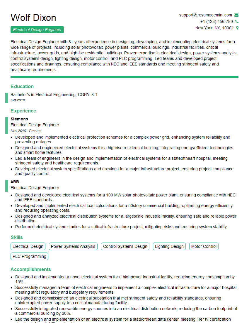
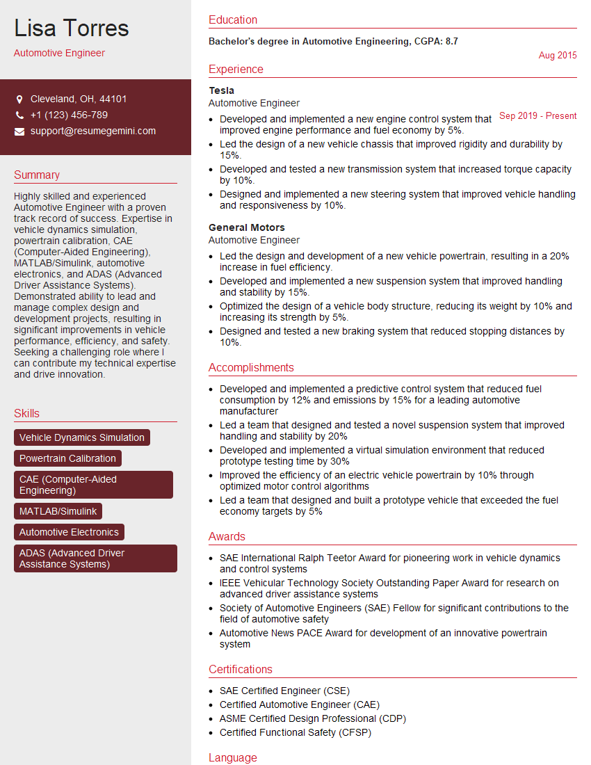
Mastering Electrical System Modeling and Simulation opens doors to exciting and impactful careers in power system engineering, renewable energy, and smart grid technologies. These skills are highly sought after, leading to rewarding opportunities for innovation and advancement. To maximize your chances of landing your dream role, it’s crucial to present your skills effectively. An ATS-friendly resume is key to getting past Applicant Tracking Systems and landing an interview. We highly recommend using ResumeGemini to build a professional and impactful resume tailored to your specific experience. ResumeGemini provides examples of resumes specifically designed for Electrical System Modeling and Simulation professionals, helping you showcase your expertise to potential employers.
Explore more articles
Users Rating of Our Blogs
Share Your Experience
We value your feedback! Please rate our content and share your thoughts (optional).
What Readers Say About Our Blog
To the interviewgemini.com Webmaster.
Very helpful and content specific questions to help prepare me for my interview!
Thank you
To the interviewgemini.com Webmaster.
This was kind of a unique content I found around the specialized skills. Very helpful questions and good detailed answers.
Very Helpful blog, thank you Interviewgemini team.
