Interviews are opportunities to demonstrate your expertise, and this guide is here to help you shine. Explore the essential Interpretation of Drawings and Specifications interview questions that employers frequently ask, paired with strategies for crafting responses that set you apart from the competition.
Questions Asked in Interpretation of Drawings and Specifications Interview
Q 1. Explain the difference between a detail drawing and an assembly drawing.
The difference between a detail drawing and an assembly drawing lies in their level of detail and purpose. Think of it like building with LEGOs: an assembly drawing shows you how all the different LEGO sub-assemblies fit together to create the final model (e.g., a car), while a detail drawing zooms in on a single, specific part (e.g., the car’s wheel) to show its precise dimensions, materials, and features.
Assembly Drawings: These drawings show how multiple components fit together to form a larger assembly. They illustrate the overall arrangement, relationships between parts, and often include exploded views for clarity. They are crucial for manufacturing and assembly processes. For example, an assembly drawing of a chair would show how the legs, seat, and back are connected.
Detail Drawings: These drawings provide detailed information about individual components within an assembly. They define precise dimensions, tolerances, materials, and manufacturing processes for a specific part. A detail drawing for the chair’s leg would show its exact length, width, shape, and the type of wood used.
In essence, assembly drawings give the ‘big picture,’ while detail drawings provide the granular information needed to manufacture individual parts.
Q 2. How do you identify revisions and updates on a drawing set?
Revisions and updates on drawings are typically indicated using a revision block or table, usually located in a title block or a designated area of the drawing sheet. This block usually includes a revision number (e.g., Rev. A, Rev. B), a description of the change, the date of the revision, and the initials or signature of the person who approved the change.
Sometimes, revisions are marked directly on the drawing using revision clouds or symbols to highlight the altered areas. These are often cross-referenced to the revision table. It’s critical to always consult the latest revision of a drawing to ensure you’re working with the most up-to-date information. Ignoring revisions can lead to costly mistakes during construction or manufacturing.
For example, a revision might change a dimension on a part, specify a different material, or correct a drafting error. The revision block ensures everyone involved is aware of these changes and uses the accurate information.
Q 3. Describe your process for interpreting a building section drawing.
Interpreting a building section drawing requires a systematic approach. Imagine slicing through a building with a giant knife – a section drawing shows you the internal structure and layout along that cut. My process involves:
- Orientation: First, I carefully identify the location and orientation of the section cut on the floor plan or site plan. This establishes the ‘viewpoint’ of the section.
- Materials and Dimensions: I then meticulously examine the drawing to identify different materials (concrete, wood, steel, etc.) and their dimensions. Pay close attention to labels and symbols.
- Structural Elements: I locate key structural components such as walls, columns, beams, foundations, and floors, noting their sizes and positions within the section.
- Utilities and Systems: I identify the locations of various building systems, including plumbing, electrical, HVAC (Heating, Ventilation, and Air Conditioning), and fire protection systems. These are often shown using standardized symbols.
- Elevation and Level Changes: I track changes in elevation throughout the section, noting floor heights, ceiling heights, and the placement of stairs or ramps.
- Notes and Specifications: Finally, I review any accompanying notes, specifications, or details that provide additional clarity or context. This step is crucial to avoid misinterpretations.
By following this systematic approach, I create a clear understanding of the building’s construction, layout, and systems along the section cut.
Q 4. What are the common symbols and abbreviations used in electrical drawings?
Electrical drawings employ a range of symbols and abbreviations to represent different electrical components and systems concisely. Some common examples include:
∅: Ground symbol∂: Lighting fixture∃: Receptacle (power outlet)S1, S2, S3...: SwitchesR1, R2, R3...: ResistorsC1, C2, C3...: CapacitorsL1, L2, L3...: Inductors- Amps (A): Unit of electric current
- Volts (V): Unit of electric potential
- Watts (W): Unit of power
- AWG (American Wire Gauge): Wire size
Understanding these symbols is crucial for interpreting electrical schematics and plans. Each symbol and abbreviation has a specific meaning, and it’s crucial to consult relevant standards and industry practices for accurate interpretation.
Q 5. How do you identify conflicts or discrepancies between drawings and specifications?
Identifying conflicts or discrepancies between drawings and specifications requires meticulous cross-referencing and a keen eye for detail. It’s a critical step to prevent costly errors during construction. My process includes:
- Simultaneous Review: I examine the drawings and specifications concurrently, referencing the relevant sections of each document.
- Detailed Comparison: I compare dimensional information, material specifications, and installation methods described in both documents. Any inconsistencies should be highlighted.
- Material Reconciliation: I ensure that material specifications in the drawings match those in the specifications document. Discrepancies might involve different grades of materials, sizes, or finishes.
- Method Comparison: I check for differences between the construction method shown in the drawing and described in the specifications. For instance, a drawing may show a specific type of fastener, while the specifications may recommend a different one.
- Documentation: I meticulously document all conflicts and discrepancies, clearly identifying their location in both drawings and specifications. This record is essential for resolving conflicts and clarifying requirements.
Resolving these conflicts typically involves discussions with the design team, contractors, and other stakeholders to determine the correct information and make necessary revisions to ensure consistency throughout the project documentation.
Q 6. Explain the significance of tolerances and dimensions on engineering drawings.
Tolerances and dimensions are fundamental aspects of engineering drawings. Dimensions specify the ideal size of a component, while tolerances define the acceptable range of variation from that ideal size. Think of it like a tailor making a suit: the dimensions are the desired measurements, and the tolerance is how much the tailor can deviate from those measurements while still making a wearable suit.
Dimensions: These are numerical values indicating the size of features like length, width, height, diameter, radius, etc. They’re crucial for manufacturing parts that fit together correctly.
Tolerances: These specify the permissible variation above and below the nominal dimension. They account for the limitations of manufacturing processes and ensure that parts are still functional even with minor variations. Tolerances are often expressed using plus/minus values (e.g., 10 ± 0.1 mm) or limits (e.g., 10.05 – 9.95 mm). Incorrect tolerance interpretation can lead to parts that don’t fit, causing costly rework or project delays.
For example, if a shaft is specified as 10mm diameter ± 0.1mm, it means the acceptable diameter range is between 9.9mm and 10.1mm. Parts outside this range would be considered non-conforming.
Q 7. How do you interpret material specifications in construction drawings?
Interpreting material specifications in construction drawings involves understanding the various notations and symbols used to describe different materials and their properties. These specifications usually include:
- Material Name: The specific type of material (e.g., concrete, steel, wood, brick). This might also include grade, strength, or other specifications.
- Material Designation: Standardized codes or designations for materials, such as ASTM (American Society for Testing and Materials) standards for steel grades.
- Physical Properties: Relevant properties of the material, such as density, compressive strength, tensile strength, or fire resistance rating.
- Surface Finish: Specific instructions on the desired surface finish of the material, such as smooth, textured, painted, or coated.
- Quantity and Dimensions: The amount of material needed and its dimensions, which might be specified in cubic yards, linear feet, or square feet.
For example, a specification might read: “Concrete, ASTM C33, 3000 psi compressive strength, 4-inch thick slab.” This clearly specifies the concrete type, its compressive strength, and the thickness of the slab. Understanding these specifications ensures the correct materials are procured and used during construction. Using the wrong material can compromise the structure’s integrity or safety.
Q 8. Describe your experience using different CAD software for reviewing drawings.
My experience with CAD software spans several platforms, including AutoCAD, Revit, and MicroStation. I’m proficient in navigating and interpreting drawings within these environments, leveraging their features for efficient review. For example, in AutoCAD, I regularly use the layer management tools to isolate specific components of a drawing for detailed inspection. In Revit, I utilize the 3D modeling capabilities to understand spatial relationships and potential clashes between different disciplines. With MicroStation, I’m adept at working with large-scale infrastructure projects and leveraging its robust referencing and annotation capabilities. My proficiency extends beyond simply viewing drawings; I can measure distances, extract data, and even make minor revisions using these tools, contributing to a smoother review process and faster turnaround times.
Q 9. How do you manage multiple drawing revisions in a project?
Managing multiple drawing revisions requires a systematic approach. I typically use a version control system, often integrated within the CAD software itself, or a dedicated platform like Autodesk Vault or similar. This ensures that each revision is clearly identified and accessible. Each revision is labeled with a unique identifier, such as a revision number (e.g., A, B, C) or a date stamp. Furthermore, a comprehensive revision log meticulously documents all changes made, the date of the change, and the person responsible. This helps in tracking the project’s evolution, facilitates easy rollback to previous versions if necessary, and minimizes confusion. Think of it like a carefully organized historical record of the project’s design journey.
Q 10. Explain the importance of proper drawing organization and filing systems.
Proper drawing organization and filing systems are paramount for efficient project management and to prevent costly errors. A well-structured system ensures that drawings are easily located, reducing the time spent searching and enhancing overall productivity. I typically use a hierarchical filing system, grouping drawings by discipline (structural, electrical, mechanical, etc.), building section, or system. Clear naming conventions, such as using project numbers and meaningful descriptions, further enhance organization. For instance, a drawing might be named Project_123_Structural_Floor_Plan_Rev_B.dwg. This allows for quick identification and retrieval. Efficient organization also prevents drawing duplication or accidental overwriting, crucial for maintaining data integrity. It’s like having a well-stocked library, where every book (drawing) has its designated shelf (folder) for easy access.
Q 11. How do you ensure compliance with building codes and regulations based on drawings and specifications?
Ensuring compliance with building codes and regulations is a critical aspect of my review process. I meticulously compare the drawings and specifications against the relevant codes, typically using the International Building Code (IBC) or local equivalents. I cross-reference dimensions, materials, fire-safety features, accessibility requirements, and other regulatory aspects. Discrepancies are meticulously documented and reported to the design team for rectification. For instance, I might check that egress paths comply with minimum width requirements specified in the code, ensuring safety. This systematic approach minimizes risks and ensures the project aligns with all legal and safety standards. It’s like a quality control check, ensuring the building is safe and legally sound.
Q 12. Describe your process for checking the completeness and accuracy of a drawing set.
Checking the completeness and accuracy of a drawing set involves a multi-step process. First, I review the index or table of contents to ensure all necessary drawings are included. Then, I perform a thorough visual inspection of each drawing, checking for missing information, inconsistencies, and errors in dimensions, notations, and details. I cross-reference drawings to identify any conflicts or discrepancies between different disciplines. For instance, I’ll check if the structural and architectural drawings align in terms of wall locations and dimensions. Next, I verify that all necessary details, such as material specifications and construction methods, are clearly indicated. Finally, I review the specifications document to ensure consistency with the drawings. This systematic approach is similar to a detective solving a case – piecing together different clues to reveal the complete and accurate picture.
Q 13. How do you communicate effectively with engineers and contractors using drawings as a reference?
Effective communication with engineers and contractors is vital. I use drawings as a common reference point, holding clear and concise discussions, pointing out specific details on the drawings to highlight areas of concern or clarification. For complex issues, I create detailed markups and annotations directly on the drawings using the CAD software’s annotation tools. This visual approach allows for precise identification and clear communication. Furthermore, I prepare concise written reports summarizing findings and recommendations, focusing on clarity and avoiding technical jargon when possible. This ensures everyone understands the key issues and the proposed solutions. This collaborative approach makes the communication process efficient and transparent.
Q 14. What are the potential consequences of misinterpreting drawings or specifications?
Misinterpreting drawings or specifications can lead to several serious consequences. On a small scale, it may cause delays in construction due to rework or material ordering errors. In more serious cases, it could lead to structural failures, safety hazards, cost overruns, and legal issues. Imagine a scenario where a misinterpretation of foundation details leads to structural instability. The consequences could be catastrophic. Therefore, a thorough understanding of drawings and specifications is not just important, it’s crucial for safety and project success. It requires meticulous attention to detail, a strong grasp of technical knowledge, and the ability to spot potential ambiguities before they become costly mistakes.
Q 15. How familiar are you with industry standards like ANSI or ISO for drawings?
My familiarity with industry standards like ANSI and ISO for drawings is extensive. I’ve worked extensively with both sets of standards throughout my career, understanding their nuances and applications across various disciplines. ANSI standards, prevalent in North America, provide guidelines for drawing formats, dimensioning, and tolerances. For instance, ANSI Y14.5 covers dimensioning and tolerancing, crucial for ensuring parts fit together correctly. ISO standards, globally recognized, offer a similar framework but with sometimes subtly different conventions. I’m proficient in interpreting both, readily identifying the standard used on a given drawing and understanding the implications of the specific standard applied. This ensures accuracy and consistency in my interpretations.
For example, understanding the difference between ANSI and ISO tolerance notations is crucial to avoid misinterpretations that could lead to manufacturing errors. An incorrectly interpreted tolerance on a critical dimension could render a part unusable. My experience allows me to seamlessly navigate these differences and ensure accurate interpretation.
Career Expert Tips:
- Ace those interviews! Prepare effectively by reviewing the Top 50 Most Common Interview Questions on ResumeGemini.
- Navigate your job search with confidence! Explore a wide range of Career Tips on ResumeGemini. Learn about common challenges and recommendations to overcome them.
- Craft the perfect resume! Master the Art of Resume Writing with ResumeGemini’s guide. Showcase your unique qualifications and achievements effectively.
- Don’t miss out on holiday savings! Build your dream resume with ResumeGemini’s ATS optimized templates.
Q 16. How do you identify and resolve conflicts between drawings and on-site conditions?
Identifying and resolving conflicts between drawings and on-site conditions requires a systematic approach. First, I meticulously document the discrepancies using photographs, sketches, and detailed notes. This forms a comprehensive record for further analysis. Then, I carefully compare the existing conditions against the drawings, noting where discrepancies occur. This often involves verifying dimensions, locations, and material types. Next, I investigate the reasons behind the discrepancies. Possible causes could include design revisions not reflected in the on-site construction, errors in the original drawings, or even unforeseen site conditions.
Once the root cause is determined, I collaborate with the project team – architects, engineers, contractors – to develop a resolution. This may involve issuing field change orders, updating the drawings to reflect the as-built conditions, or proposing design modifications to accommodate the existing conditions. Throughout this process, clear communication and proper documentation are paramount to ensure everyone is informed and agrees on the solution. Consider a scenario where a pipe’s location on site differs from the drawings. Detailed documentation of the discrepancy, investigation of the cause (possibly a design oversight), and collaboration with the engineering team to determine a safe and compliant solution are critical steps in resolving this conflict.
Q 17. Describe your experience in using BIM software for drawing interpretation and coordination.
I have significant experience using BIM (Building Information Modeling) software for drawing interpretation and coordination. I’m proficient in several platforms, including Revit and ArchiCAD. BIM software revolutionizes drawing interpretation by providing a 3D model, allowing for better visualization and clash detection. For instance, using Revit, I can easily identify conflicts between architectural, structural, and MEP (Mechanical, Electrical, and Plumbing) systems before construction begins. This prevents costly rework and delays later in the project.
My experience extends beyond visualization. I use BIM to coordinate different disciplines’ drawings, ensuring seamless integration of various systems. I can analyze quantities, generate schedules, and produce detailed reports directly from the model. BIM also allows for efficient clash detection, where the software highlights areas of conflict between different elements in the model, such as pipes intersecting with beams. I then work collaboratively with other designers to resolve these clashes, making the design more constructible and cost-effective. My ability to use BIM not only improves my efficiency but also contributes to better project outcomes.
Q 18. How do you handle ambiguous or unclear information in drawings or specifications?
Handling ambiguous or unclear information in drawings or specifications requires a methodical approach. First, I carefully review the entire set of drawings and specifications, searching for any related information that might clarify the ambiguity. This might involve cross-referencing different sheets or sections of the document. Next, I use my experience and knowledge to interpret the unclear information, using logic and engineering principles to deduce the intended meaning. If the ambiguity cannot be resolved through internal analysis, I follow established procedures. This usually involves contacting the design team or relevant stakeholders for clarification. Documentation of the ambiguity and the steps taken to resolve it are meticulously recorded.
Consider a drawing with an unclear dimension. Instead of guessing, I would first search for related drawings or specifications. If the ambiguity persists, I would contact the architect or engineer to request clarification, ensuring that the resolution is documented. This cautious approach minimizes the risks of misinterpretations and errors.
Q 19. What is your approach to learning a new type of drawing or specification?
My approach to learning a new type of drawing or specification is systematic and thorough. I begin by understanding the purpose and context of the drawing. Who created it? What is it intended to convey? Then I focus on identifying the key elements and conventions used in the drawings. This often involves referring to relevant standards and guides. I might look for legend tables, detail drawings, and any accompanying notes to comprehend the symbols, notations, and dimensions. I then work through a series of sample drawings, reinforcing my understanding and building confidence.
Hands-on practice is crucial. I find the best way to learn is by working through actual drawings, applying what I’ve learned to real-world problems. If possible, I seek feedback from experienced colleagues to identify any areas where I need improvement. Continuous learning and seeking clarification ensures I maintain expertise across various drawing types.
Q 20. Explain your experience using different drawing formats (e.g., PDF, DWG, DXF).
I’m proficient in using various drawing formats, including PDF, DWG, and DXF. PDF is widely used for sharing and archiving drawings due to its universal accessibility. DWG is the native format for AutoCAD, providing access to the full editing capabilities of the software. DXF is an exchange format, useful for sharing drawings between different CAD programs. My experience ensures seamless transition between these formats, understanding the strengths and limitations of each. For example, while PDF provides excellent visual fidelity, it lacks the editing features of DWG. I would choose the appropriate format based on the project’s requirements; for example, utilizing DWG for editing and PDF for distribution.
My experience goes beyond simple file handling. I can effectively utilize the functionalities within each format, such as layer management in DWG and PDF annotation tools for collaboration and review. I’m also proficient in using plugins or extensions that enhance the functionality of these file types.
Q 21. How do you prioritize the information within a complex drawing set?
Prioritizing information in a complex drawing set requires a structured approach. I begin by understanding the overall project goals and the sequence of construction. This helps identify which drawings are critical to each stage of the project. Then, I examine the drawing hierarchy, looking for key drawings that provide a general overview and those that present detailed information. This might include architectural plans, structural drawings, and MEP schematics. I then focus on drawings related to the current construction phase, paying close attention to details such as dimensions, tolerances, and specifications related to the work being performed.
Imagine a large-scale project; I would prioritize the site plan and floor plans initially, then move to structural and MEP drawings relevant to the current phase of construction. This strategic approach ensures focus on the most critical information at any given time and optimizes workflow.
Q 22. How do you identify the scale of a drawing and its impact on measurements?
Identifying the scale of a drawing is fundamental. The scale is usually shown in a title block or drawing header, typically expressed as a ratio, like 1:100 or 1/4″=1′. This means that 1 unit on the drawing represents 100 units in reality (in the first example), or 1/4 inch on the drawing equals 1 foot in reality. Understanding the scale is crucial for accurate measurements. To obtain real-world dimensions, you simply multiply the measured drawing dimension by the scale factor. For example, if a wall measures 5cm on a 1:100 drawing, the actual wall length is 5cm * 100 = 500cm or 5 meters.
Incorrect scale interpretation leads to significant errors in construction. Imagine misinterpreting a 1:50 scale as 1:100 – you would end up with a structure half the intended size! Always double-check the scale before undertaking any measurements or calculations.
Q 23. Explain how you use drawings to understand the sequence of construction activities.
Drawings, particularly architectural and engineering drawings, often implicitly or explicitly show the sequence of construction activities. Think of it like a recipe. Different drawings, like foundation plans, framing plans, and finishing plans, represent different stages. The order of the drawings themselves can suggest a sequence. Details like phasing notations, callouts referencing earlier plans, and even the layer order in digital drawings can indicate precedence. For example, foundation drawings would precede framing plans, which precede MEP (Mechanical, Electrical, Plumbing) drawings. Specific details within the drawings, such as numbered sequences or detailed descriptions, will further clarify the construction sequence.
Furthermore, you need to understand the logical order of construction activities. You wouldn’t install interior finishes before the walls are built. By carefully reviewing all the drawings and specifications, you can construct a clear timeline or workflow that aligns with the overall project plan.
Q 24. Describe your experience using cross-references within a drawing set.
Cross-references are vital for navigating a complex drawing set. They are essentially pointers linking one drawing to another. These might appear as notes like “See Detail A on Sheet 3” or a specific reference number linking to a detail drawing on a separate sheet. Effective use of cross-references allows for a clear understanding of interrelationships between different aspects of the project. For instance, a section detail might reference a larger plan drawing for context, or an elevation drawing may show specific features called out on a detail drawing.
In my experience, mastering the cross-referencing system is key to efficiently understanding the entire design intent. I use a systematic approach – starting with the general arrangement drawings and following the cross-references to understand specific components and details.
Q 25. How do you interpret and apply material take-offs from drawings and specifications?
Material take-offs (MTOs) involve quantifying materials required for construction based on drawings and specifications. It’s a critical step in cost estimation and procurement. This process combines meticulous measurement from drawings (lengths, areas, volumes) with information from specifications (material types, sizes, allowances). For instance, the drawings show wall dimensions and the specifications detail the brick type, dimensions, and mortar requirements. By combining this information, I can calculate the total number of bricks needed, accounting for waste.
Software like spreadsheets or specialized estimating tools greatly assists in calculating material quantities efficiently. Accurate MTOs minimize waste, ensure timely procurement, and lead to more accurate project budgeting.
Q 26. What methods do you employ to ensure accurate interpretation of architectural drawings?
Accurate interpretation of architectural drawings requires a multi-faceted approach. First, I thoroughly review the title block for crucial information: scale, revision dates, project name, and relevant details. Next, I systematically work through the drawing set, starting with general arrangement plans (site plan, floor plans) before delving into specific details. I always verify dimensions using the specified scale and check for consistency across multiple drawings.
I use various techniques to confirm understanding: comparing different views of the same element (plan, section, elevation); reviewing notes, legends, and symbols; and cross-referencing details. When ambiguity arises, I don’t hesitate to contact the design team for clarification.
Q 27. How do you use drawings to estimate the cost of a project?
Drawings are fundamental to project cost estimation. They provide the basis for material take-offs, as discussed earlier. Once the quantities of materials are determined, the cost can be estimated by multiplying the quantities by the unit prices obtained from suppliers. The drawings also help determine labor requirements. For example, the complexity of a structure shown in the drawings can be a factor in estimating labor hours and costs. Furthermore, the drawings help identify specialized elements or unusual detailing that might necessitate additional costs.
However, cost estimation based on drawings alone is incomplete. Specifications provide detailed information about material quality and finishes, significantly influencing the cost. Experienced estimators integrate data from both drawings and specifications for a more accurate project budget.
Q 28. Describe a situation where you had to interpret a complex drawing or specification, and how you successfully addressed it.
I once encountered a situation where conflicting information was presented on different drawings within a large-scale commercial project. One drawing indicated a particular structural support system, while a separate structural detail suggested a different approach. This discrepancy could have resulted in serious errors during construction.
My approach was systematic: I first carefully reviewed both conflicting drawings, comparing all relevant dimensions, notes, and references. Then, I examined the project specifications for relevant clauses that might clarify the intent. Finally, I contacted the structural engineer to discuss the discrepancies and obtain a definitive resolution. The engineer confirmed one drawing was outdated and provided a revised detail, preventing potential structural issues.
Key Topics to Learn for Interpretation of Drawings and Specifications Interview
- Drawing Types & Standards: Understanding different drawing types (e.g., architectural, mechanical, electrical) and relevant industry standards (e.g., ASME, ISO).
- Dimensioning and Tolerancing: Interpreting dimensions, tolerances, and geometric dimensioning and tolerancing (GD&T) symbols to ensure accuracy in construction or manufacturing.
- Material Specifications: Identifying and understanding material properties, specifications, and their implications for project success. This includes recognizing material designations and selecting appropriate materials based on design requirements.
- Section Views and Details: Interpreting sectional views, detail drawings, and assembly drawings to fully grasp the design intent.
- Bill of Materials (BOM): Understanding and utilizing BOMs to identify components and quantities needed for a project.
- Practical Application: Discuss scenarios where you’ve successfully interpreted drawings and specifications to solve a problem or contribute to a project. Highlight your problem-solving skills and ability to identify potential issues.
- Technical Specifications and Codes: Demonstrate familiarity with relevant building codes, industry regulations, and technical specifications impacting design and construction.
- Blueprint Reading Proficiency: Show your ability to efficiently and accurately read blueprints, identify critical information, and understand design intent.
- Communication & Collaboration: Explain how you effectively communicate design requirements and specifications to team members and stakeholders.
Next Steps
Mastering the interpretation of drawings and specifications is crucial for career advancement in engineering, architecture, and construction. A strong understanding of these skills demonstrates your technical proficiency and problem-solving abilities, opening doors to more challenging and rewarding roles. To maximize your job prospects, create a compelling, ATS-friendly resume that showcases your expertise. ResumeGemini is a trusted resource to help you build a professional and impactful resume that highlights your skills and experience. Examples of resumes tailored to Interpretation of Drawings and Specifications are available to further assist you in crafting a winning application.

Contract Administrator Resume Sample
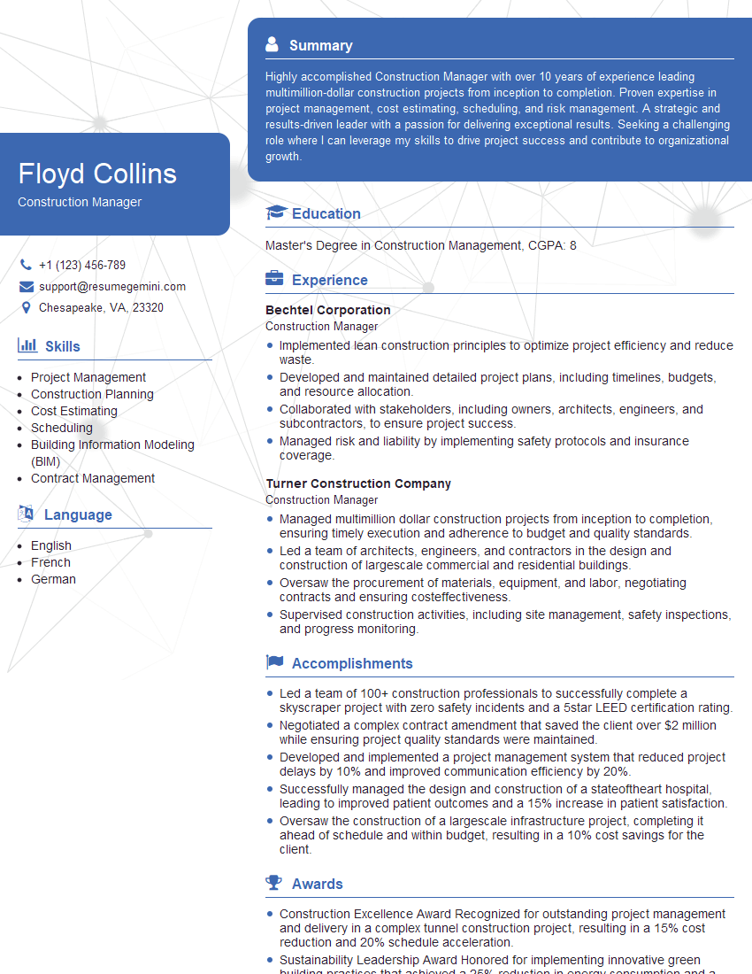
Construction Manager Resume Sample

Construction Superintendent Resume Sample
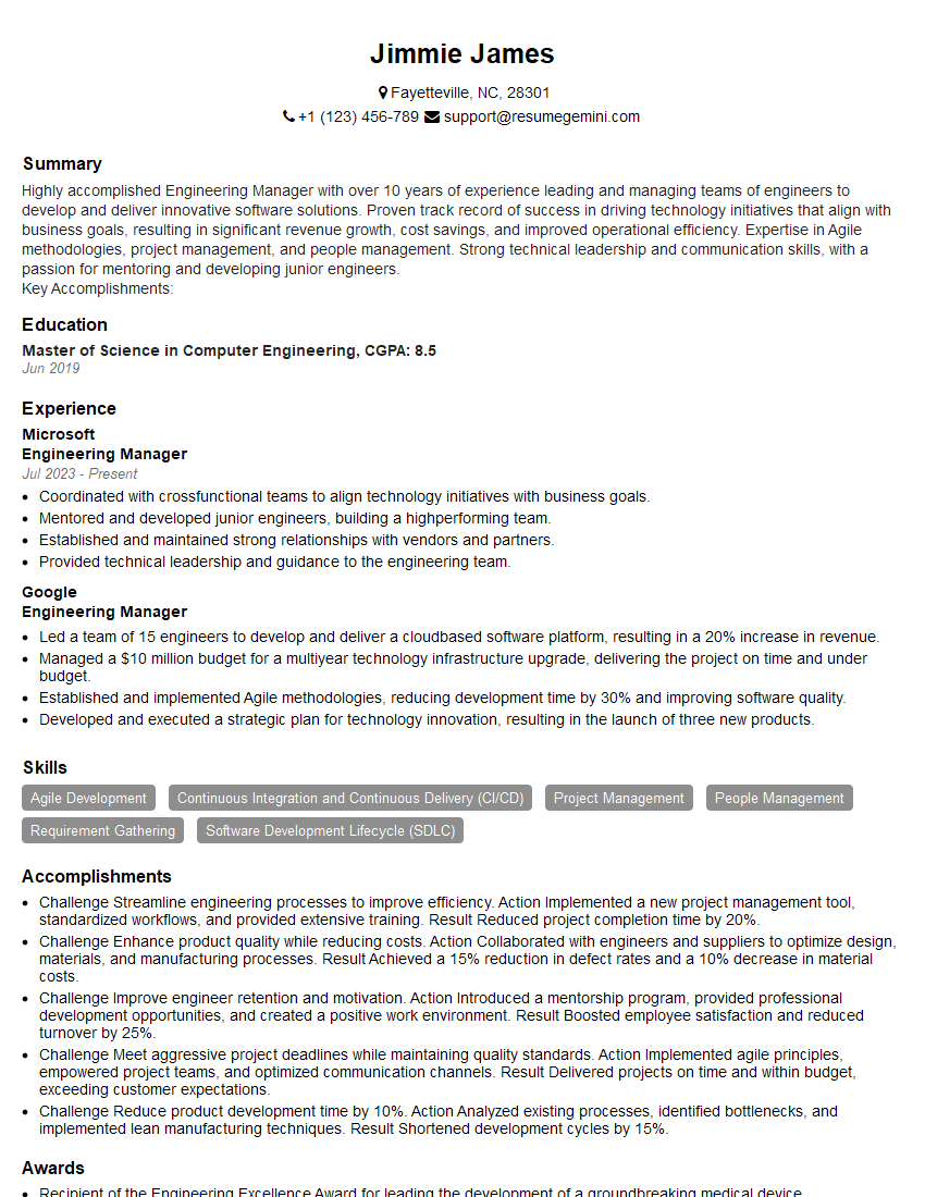
Engineering Manager Resume Sample
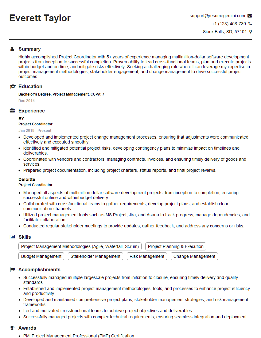
Project Coordinator Resume Sample

Project Engineer Resume Sample
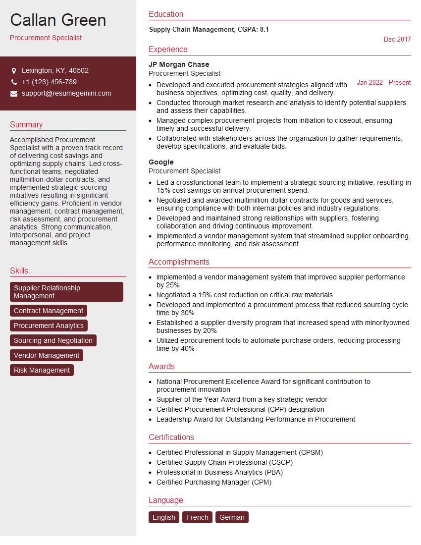
Procurement Specialist Resume Sample
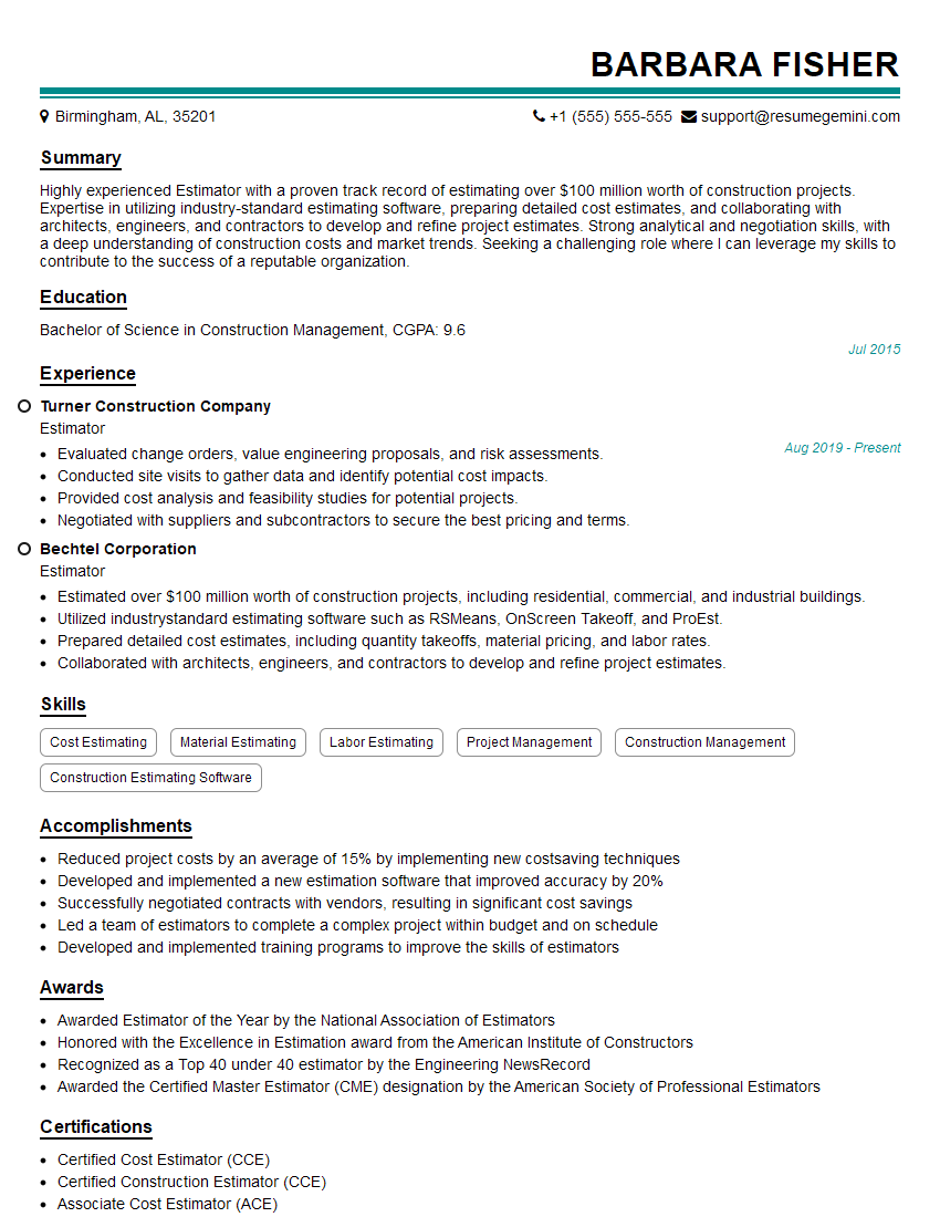
Estimator Resume Sample
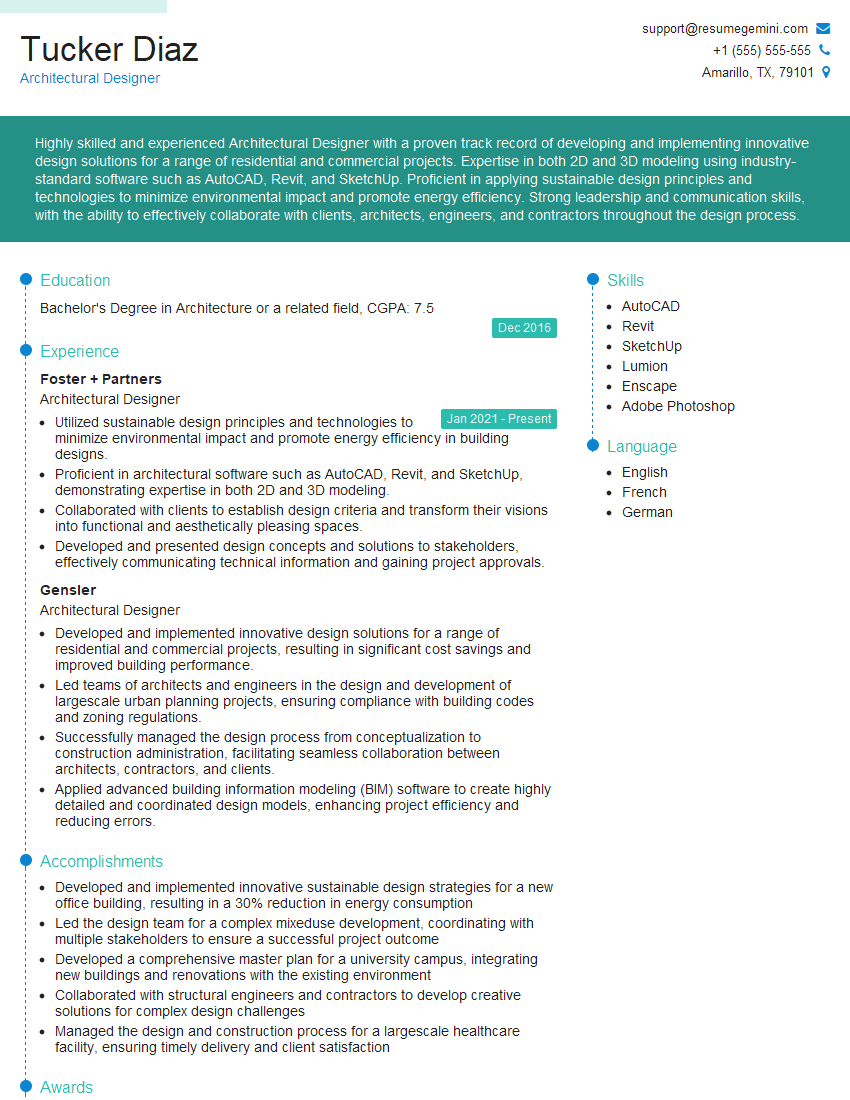
Architectural Designer Resume Sample
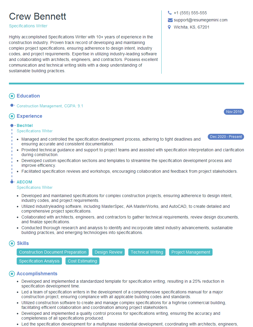
Specifications Writer Resume Sample
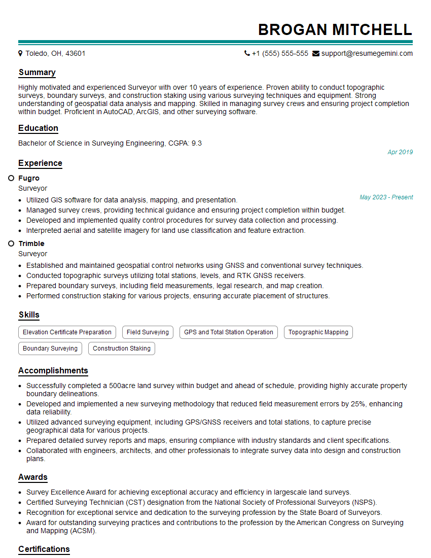
Surveyor Resume Sample

Engineering Technician Resume Sample
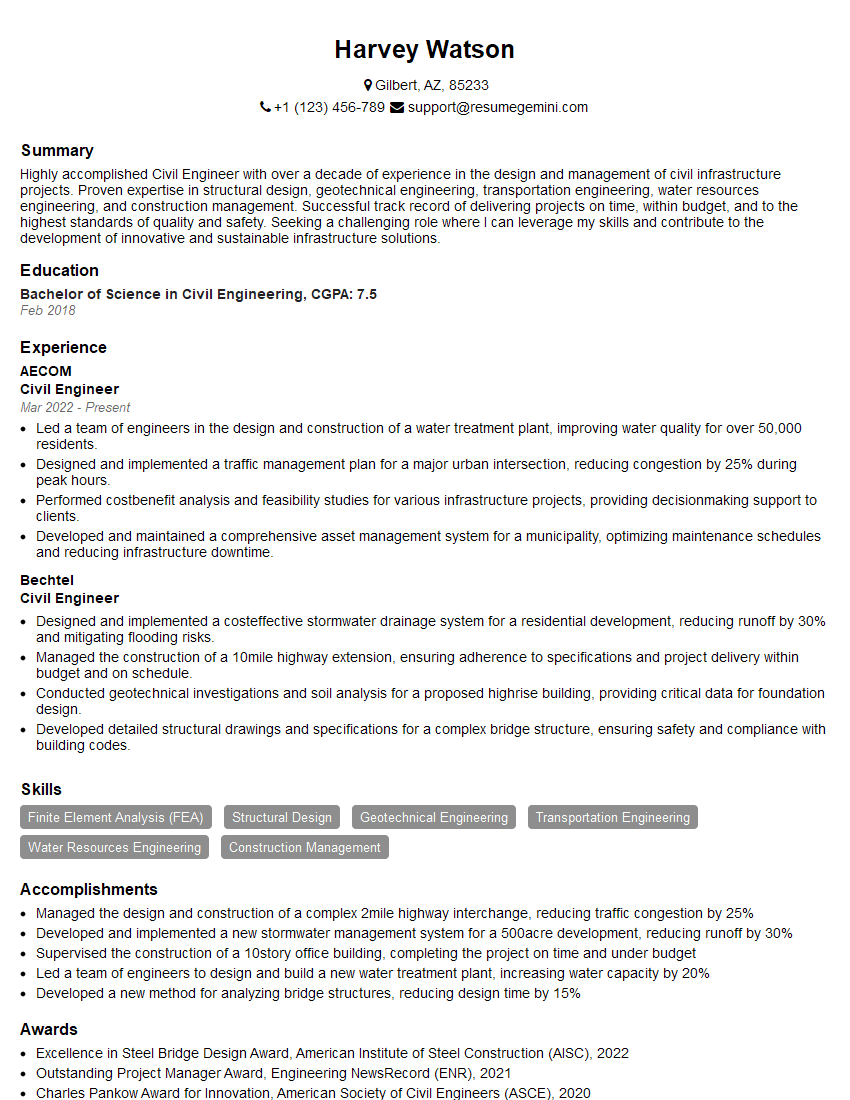
Civil Engineer Resume Sample
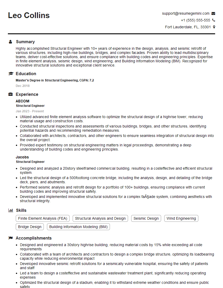
Structural Engineer Resume Sample

Electrical Engineer Resume Sample
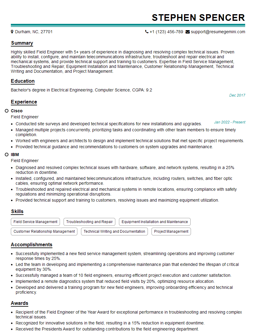
Field Engineer Resume Sample
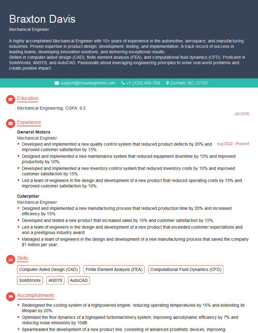
Mechanical Engineer Resume Sample
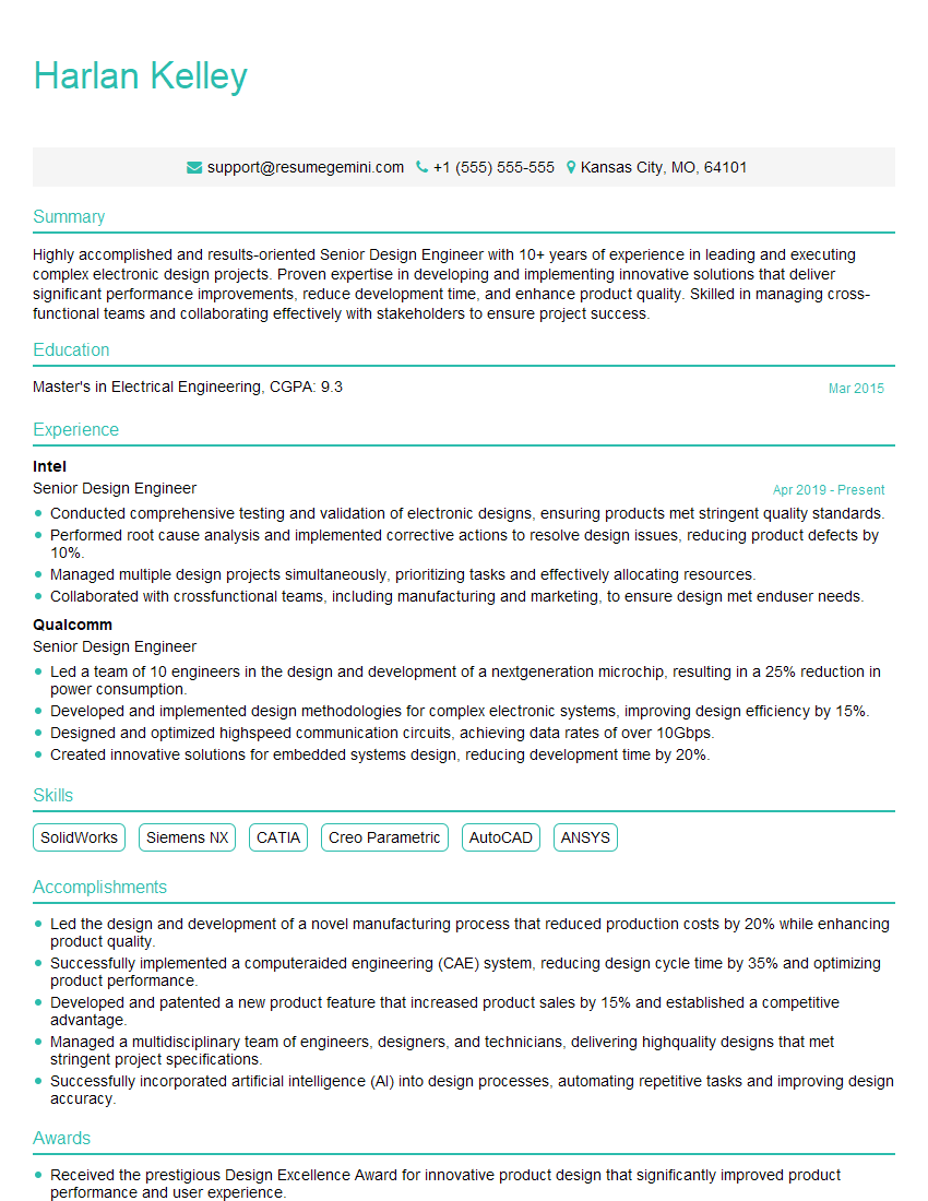
Senior Design Engineer Resume Sample
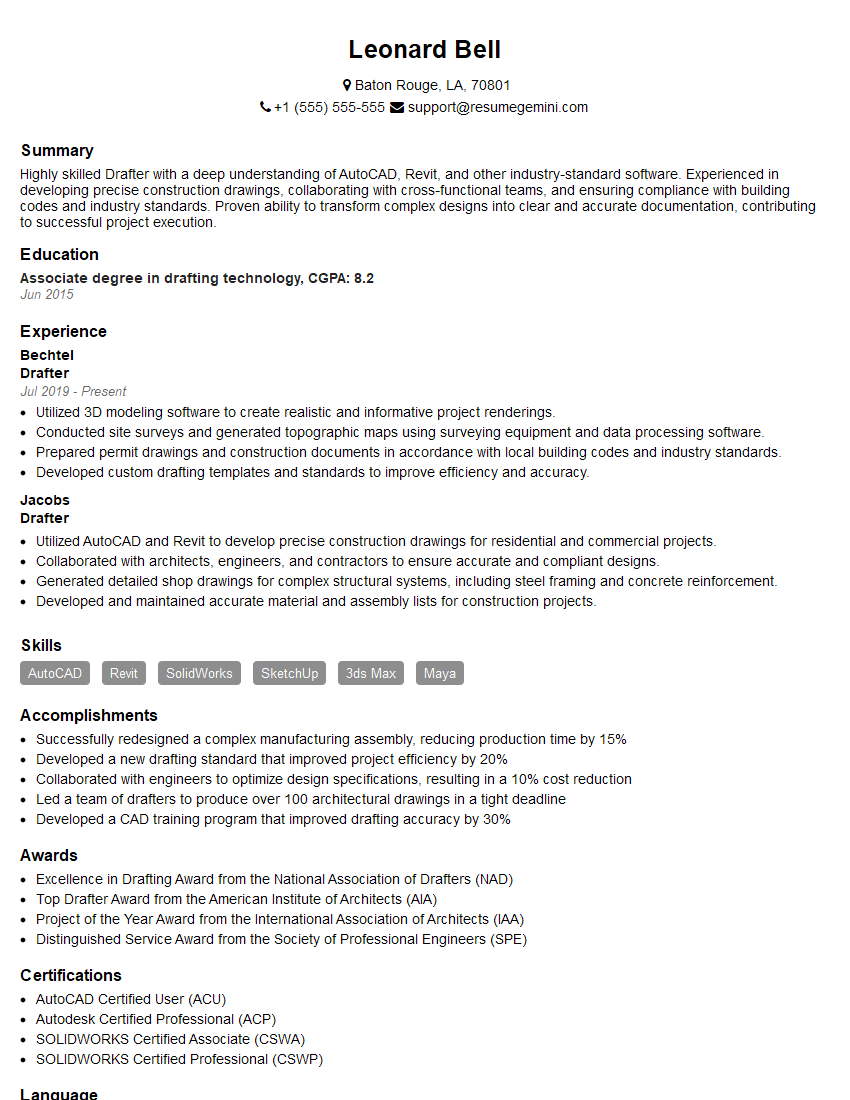
Drafter Resume Sample
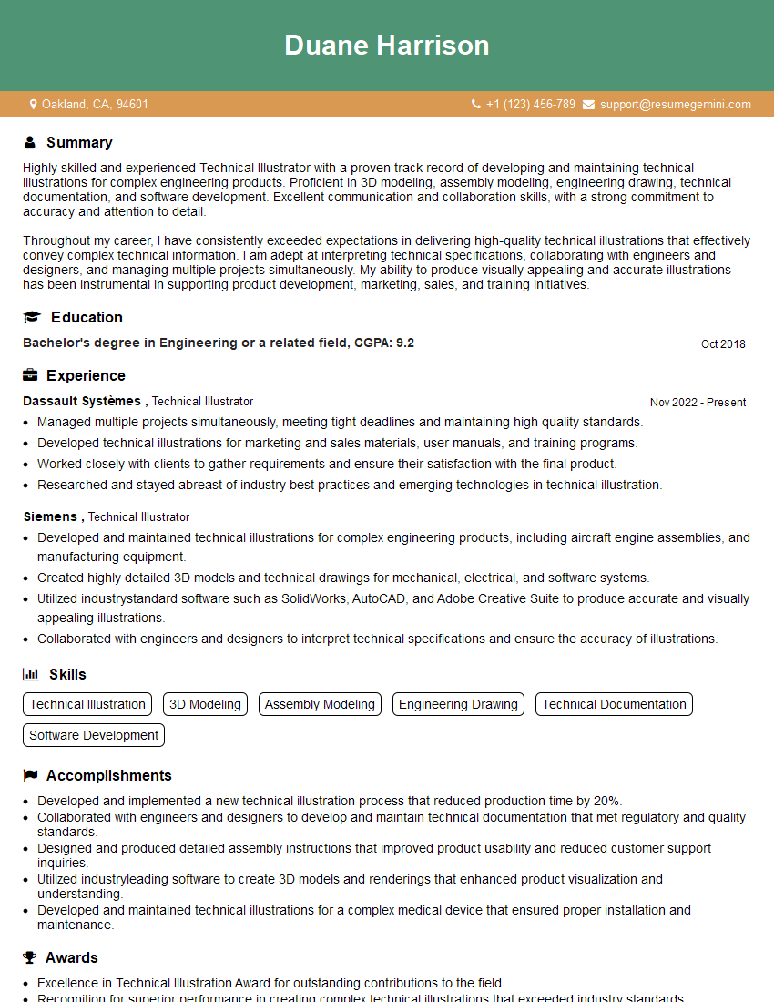
Technical Illustrator Resume Sample
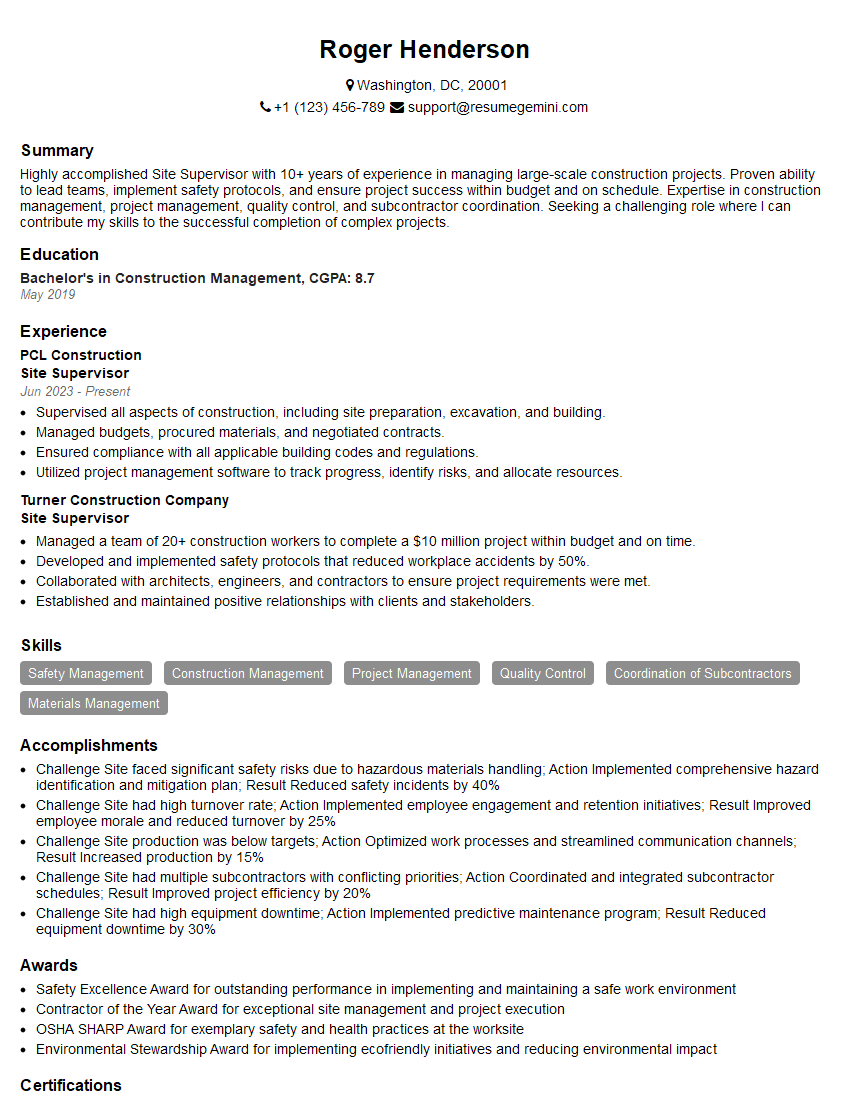
Site Supervisor Resume Sample

Quality Control Inspector Resume Sample
- Contract Administrator
- Construction Manager
- Construction Superintendent
- Engineering Manager
- Project Coordinator
- Project Engineer
- Procurement Specialist
- Estimator
- Architectural Designer
- Specifications Writer
- Surveyor
- Engineering Technician
- Civil Engineer
- Structural Engineer
- Electrical Engineer
- Field Engineer
- Mechanical Engineer
- Senior Design Engineer
- Drafter
- Technical Illustrator
- Site Supervisor
- Quality Control Inspector
Explore more articles
Users Rating of Our Blogs
Share Your Experience
We value your feedback! Please rate our content and share your thoughts (optional).
What Readers Say About Our Blog
To the interviewgemini.com Webmaster.
Very helpful and content specific questions to help prepare me for my interview!
Thank you
To the interviewgemini.com Webmaster.
This was kind of a unique content I found around the specialized skills. Very helpful questions and good detailed answers.
Very Helpful blog, thank you Interviewgemini team.