Cracking a skill-specific interview, like one for Knowledge of Pipe Sizing and Calculation, requires understanding the nuances of the role. In this blog, we present the questions you’re most likely to encounter, along with insights into how to answer them effectively. Let’s ensure you’re ready to make a strong impression.
Questions Asked in Knowledge of Pipe Sizing and Calculation Interview
Q 1. Explain the Darcy-Weisbach equation and its application in pipe sizing.
The Darcy-Weisbach equation is a fundamental formula in fluid mechanics used to calculate the head loss (pressure drop) due to friction in a pipe. It’s crucial for accurate pipe sizing because it directly relates the flow rate, pipe diameter, fluid properties, and the pipe’s roughness.
The equation is: hf = f * (L/D) * (V²/2g)
hfrepresents the head loss due to friction (meters).fis the Darcy friction factor (dimensionless), a function of the Reynolds number and the pipe’s roughness.Lis the pipe length (meters).Dis the pipe diameter (meters).Vis the average flow velocity (meters/second).gis the acceleration due to gravity (approximately 9.81 m/s²).
Application in Pipe Sizing: Imagine designing a water supply system. Knowing the required flow rate and the acceptable head loss, you can use the Darcy-Weisbach equation iteratively to determine the appropriate pipe diameter. You’ll need to estimate the friction factor (often using Moody charts or correlations), then solve for D. If the calculated diameter isn’t a standard size, you’d adjust and recalculate until a suitable size is found. This ensures sufficient flow while minimizing energy losses.
Q 2. Describe the difference between laminar and turbulent flow in pipes.
The flow regime in a pipe is classified as either laminar or turbulent, depending on the Reynolds number (Re), a dimensionless quantity that relates inertial forces to viscous forces.
Laminar Flow: Occurs at low Reynolds numbers (Re < 2000). The fluid moves in smooth, parallel layers, with minimal mixing between layers. Head losses are primarily due to viscous effects and can be accurately predicted using the Hagen-Poiseuille equation. Think of honey slowly flowing down a spoon – that's laminar.
Turbulent Flow: Occurs at high Reynolds numbers (Re > 4000). The fluid motion is chaotic and irregular, characterized by swirling eddies and significant mixing. Head losses are much higher than in laminar flow and are strongly influenced by pipe roughness. Imagine a rushing river – that’s turbulent flow.
Transitional Flow: Exists in the range of 2000 < Re < 4000, where the flow characteristics are unstable and can switch between laminar and turbulent.
Q 3. How do you account for friction losses in pipe sizing calculations?
Friction losses are a significant factor in pipe sizing, representing energy dissipation due to the interaction between the fluid and the pipe wall. They are primarily accounted for using empirical equations like the Darcy-Weisbach equation (explained in question 1) or the Hazen-Williams equation (explained later).
Methods for accounting for friction losses:
- Darcy-Weisbach Equation: Provides a more accurate representation, especially for turbulent flow, but requires determining the friction factor (f), which can be done using Moody charts or correlations based on the Reynolds number and pipe roughness.
- Hazen-Williams Equation: A simpler empirical equation suitable for water flow in pipes. It’s less accurate than Darcy-Weisbach but easier to use for preliminary calculations.
- Equivalent Length Method: Accounts for losses in fittings (elbows, valves, etc.) by adding their equivalent length to the pipe length in the friction loss calculation.
In practice, engineers often use iterative methods, starting with an estimated diameter, calculating the head loss, and then adjusting the diameter until the desired flow rate and head loss are achieved.
Q 4. What are the common methods used for determining pipe diameter?
Several methods determine the appropriate pipe diameter, often involving iterative calculations:
- Using the Darcy-Weisbach Equation: This is the most accurate approach, as explained earlier. It requires knowledge of flow rate, head loss, fluid properties, and pipe roughness.
- Using the Hazen-Williams Equation: A simpler alternative for water flow, offering a direct solution for diameter if the other parameters are known.
- Trial-and-Error Method: An iterative approach starting with an estimated diameter, calculating the head loss, and adjusting the diameter until the design criteria are met.
- Using Pipe Sizing Software or Online Calculators: These tools automate the calculations, often incorporating various empirical equations and considering pipe material properties and fittings.
The choice of method depends on the desired accuracy, the availability of data, and the complexity of the piping system. For complex systems with many fittings and varying flow conditions, using software is highly recommended.
Q 5. Explain the concept of head loss in piping systems.
Head loss in piping systems represents the energy loss of the fluid as it flows through the pipes. This energy loss is primarily due to friction between the fluid and the pipe walls (friction losses) and minor losses due to changes in direction, fittings (elbows, valves), and other flow restrictions.
Types of Head Loss:
- Friction Losses: These are the major losses and are calculated using equations like the Darcy-Weisbach or Hazen-Williams equations. They depend on the pipe length, diameter, roughness, and flow velocity.
- Minor Losses: These losses occur at fittings, valves, and changes in pipe diameter. They are often calculated using empirical coefficients (K-factors) that depend on the type and geometry of the fitting.
Importance in Pipe Sizing: Head loss directly impacts the pump power required to maintain the desired flow rate. Accurate head loss calculation ensures efficient system design by minimizing energy consumption and selecting appropriately sized pumps.
Q 6. How does fluid viscosity affect pipe sizing?
Fluid viscosity significantly affects pipe sizing because it influences the flow regime (laminar or turbulent) and the magnitude of friction losses. Viscosity is a measure of a fluid’s resistance to flow. Higher viscosity means greater resistance.
Impact on Pipe Sizing:
- Higher Viscosity: Leads to increased friction losses for the same flow rate, requiring a larger diameter pipe to maintain the desired flow. The Reynolds number will be lower, potentially leading to laminar flow.
- Lower Viscosity: Results in lower friction losses, allowing for smaller diameter pipes for the same flow rate. The Reynolds number will likely be higher, indicating turbulent flow.
The viscosity is incorporated into the Reynolds number calculation (Re = (ρVD)/μ, where ρ is density, V is velocity, D is diameter, and μ is dynamic viscosity). The Reynolds number then helps determine the friction factor used in the Darcy-Weisbach equation.
Q 7. What is the Hazen-Williams equation, and when is it used?
The Hazen-Williams equation is an empirical formula used to estimate head loss due to friction in water pipelines. It’s simpler than the Darcy-Weisbach equation, making it suitable for preliminary design or when high accuracy isn’t critical.
The equation is: hf = (4.52 * L * Q1.85)/(C1.85 * D4.87)
hfis the head loss (meters).Lis the pipe length (meters).Qis the flow rate (cubic meters per second).Cis the Hazen-Williams coefficient (dimensionless), representing the pipe’s roughness. It ranges from approximately 60 (very rough) to 150 (very smooth) for most types of pipes.Dis the pipe diameter (meters).
When to Use it: The Hazen-Williams equation is often preferred for water distribution systems where the fluid is water, and high accuracy is not strictly required. Its simplicity facilitates quick estimations, making it useful in preliminary design and cost estimations. However, it’s less accurate than Darcy-Weisbach for non-water fluids or conditions far from its applicability range.
Q 8. Describe the different types of pipe materials and their suitability for various applications.
Pipe materials significantly impact a system’s performance, lifespan, and cost. The choice depends on the fluid being transported, pressure, temperature, and the environment. Here are some common types:
- Steel: Strong, durable, and widely used for high-pressure applications. Carbon steel is common but susceptible to corrosion; stainless steel offers better corrosion resistance. Think of high-pressure pipelines transporting oil or gas.
- Copper: Excellent corrosion resistance, making it suitable for potable water distribution. However, it’s more expensive than steel and less suitable for high temperatures or pressures. Common in residential plumbing.
- PVC (Polyvinyl Chloride): A cost-effective, lightweight, and corrosion-resistant plastic commonly used for drainage, irrigation, and low-pressure applications. Think of water supply lines in less demanding applications.
- HDPE (High-Density Polyethylene): Another plastic offering high strength, flexibility, and excellent chemical resistance. Often used for gas distribution and underground water lines. Its flexibility makes it easier to install in challenging terrain.
- Cast Iron: Historically prevalent, it offers good strength and durability. However, its susceptibility to corrosion and breakage is a major drawback; ductile iron offers improved properties.
Selecting the right material involves careful consideration of all these factors. For instance, while steel offers high strength, using it for potable water might necessitate additional corrosion protection, increasing costs. Conversely, using PVC in high-pressure applications would compromise safety.
Q 9. How do you account for minor losses in pipe sizing calculations (e.g., valves, fittings)?
Minor losses in pipe sizing, due to valves, fittings, bends, and other components, are significant and cannot be ignored. They represent energy dissipation due to friction and flow disturbances. We account for them using the concept of equivalent length.
Each fitting or valve is assigned an equivalent length of straight pipe that would cause a similar pressure drop. These equivalent lengths are usually provided by manufacturers or found in engineering handbooks. They’re added to the actual pipe length to calculate the total equivalent length. The Darcy-Weisbach equation (or similar) is then used to calculate the head loss, incorporating this total equivalent length.
For example: Imagine a pipeline with 100m of pipe and three 90-degree elbows, each with an equivalent length of 3m. The total equivalent length would be 100m + (3m * 3) = 109m. This 109m is then used in head loss calculations to accurately determine pressure drop and pump requirements.
Q 10. Explain the concept of equivalent length in piping systems.
Equivalent length simplifies pipe sizing calculations by representing the pressure drop caused by fittings and valves as an equivalent length of straight pipe. It’s crucial because fittings disrupt smooth flow, causing additional friction and head loss. Instead of calculating the complex pressure drop for each component individually, we assign an equivalent length which simplifies the calculation.
Think of it like this: Imagine you’re driving on a highway. Smooth stretches represent the straight pipe, but when you encounter sharp turns or traffic jams (fittings), it takes you more time and effort, even if the total distance is short. The equivalent length accounts for this extra “effort,” representing the extra pressure loss in our pipe system.
Determining equivalent lengths often involves using manufacturer’s data or established standards and tables which list equivalent lengths for common fittings based on their type and diameter.
Q 11. What are the considerations for selecting appropriate pipe fittings?
Selecting appropriate pipe fittings is critical for ensuring proper flow, minimizing pressure loss, and maintaining system integrity. Several factors need consideration:
- Type of fitting: Elbows, tees, reducers, unions, valves (gate, globe, ball, check, etc.) each have distinct flow characteristics and pressure drop implications. The choice depends on the specific application.
- Material compatibility: The fitting material must be compatible with the pipe material and the fluid being transported to prevent corrosion or chemical reactions.
- Pressure rating: The fitting must be rated for the maximum operating pressure of the system.
- Temperature rating: The fitting must withstand the operating temperature without degrading.
- Size and geometry: The fitting must fit the pipe diameter and flow requirements. Smooth transitions minimize pressure loss.
- Ease of installation and maintenance: Consider ease of access, assembly, and potential future maintenance needs.
For example, using a low-pressure rated fitting in a high-pressure system could lead to catastrophic failure. Similarly, using a fitting with sharp bends increases frictional losses, requiring a more powerful pump.
Q 12. How do you determine the required pump power for a given piping system?
Determining pump power involves calculating the total head (total energy required to move the fluid) and flow rate. The total head comprises several components:
- Static head: The vertical distance the fluid needs to be lifted.
- Friction head loss: Losses due to friction in the pipe and fittings (calculated using the Darcy-Weisbach equation or similar methods).
- Velocity head: Energy associated with the fluid’s velocity.
- Minor losses: Head losses from fittings and valves (accounted for using equivalent lengths).
Once the total head (H) and flow rate (Q) are known, pump power (P) can be calculated using the following formula (assuming efficiency η):
P = (ρ * g * Q * H) / η
Where:
ρis the fluid densitygis the acceleration due to gravityηis the pump efficiency (typically between 0.6 and 0.8)
It’s crucial to account for all head loss components for accurate power calculations. Underestimating head loss can lead to selecting an underpowered pump, resulting in insufficient flow or system failure.
Q 13. Describe the process of performing a pipe stress analysis.
Pipe stress analysis assesses the forces and stresses acting on a piping system due to factors like pressure, temperature variations, weight, and seismic activity. The goal is to ensure the system can withstand these stresses without failure or excessive deformation. This involves:
- Defining the system: Creating a detailed model of the piping system, including pipe geometry, supports, and constraints.
- Applying loads: Determining the pressure, temperature gradients, and other loads acting on the system.
- Performing analysis: Utilizing Finite Element Analysis (FEA) software or other calculation methods to analyze stresses, strains, and displacements.
- Evaluating results: Comparing the calculated stresses with allowable stresses for the pipe material to ensure safety.
- Iteration and optimization: Adjusting the system design (e.g., adding supports, changing pipe diameter) as needed to meet safety standards.
Without pipe stress analysis, you risk designing a system that might fail under operating conditions, causing leaks, structural damage, or even catastrophic failure, especially in critical systems like those in power plants or chemical processing facilities.
Q 14. What are the safety considerations in pipe design and installation?
Safety in pipe design and installation is paramount. Key considerations include:
- Material Selection: Choosing materials appropriate for the fluid being transported, pressure, temperature, and environmental conditions to prevent corrosion, leakage, or breakage.
- Pressure Testing: Performing pressure tests on the completed system to verify its ability to withstand operating pressures and identify any leaks before commissioning.
- Proper Support and Restraints: Providing adequate supports and restraints to prevent excessive movement or stress due to weight, thermal expansion, or vibrations.
- Corrosion Protection: Implementing appropriate corrosion protection measures, such as coatings or cathodic protection, especially for materials susceptible to corrosion.
- Emergency Shutdown Systems: Incorporating emergency shutdown systems to quickly isolate sections of the piping system in case of leaks or other emergencies.
- Safety Valves: Installing relief valves and safety valves to protect the system from overpressure.
- Compliance with Codes and Standards: Adhering to relevant safety codes and standards (e.g., ASME B31.1, B31.3) throughout the design, fabrication, and installation process.
Neglecting these safety considerations can lead to significant risks, including environmental damage, personal injury, property damage, and economic loss. A rigorous safety approach is essential throughout the entire project lifecycle.
Q 15. Explain the importance of pipe supports and their design.
Pipe supports are crucial for the safe and efficient operation of any piping system. They prevent excessive stress, vibration, and movement that could lead to leaks, failures, and even catastrophic events. Design involves considering several factors including pipe weight, fluid pressure, thermal expansion, wind loads, seismic activity, and the type of support used.
For example, a long pipeline carrying hot oil will experience significant thermal expansion. Without properly designed supports allowing for this expansion, the pipe could buckle or rupture. Similarly, a pipeline in an earthquake-prone zone requires supports that can withstand seismic forces.
Support design typically involves calculations to determine the required support spacing and the type of support (e.g., anchors, guides, hangers) based on the anticipated loads. Software tools are often employed to model and analyze the piping system’s behavior under various loading conditions.
- Anchors: Restrict both axial and lateral movement.
- Guides: Restrict lateral movement but allow axial movement.
- Hangers: Support the weight of the pipe and allow for axial and thermal movement.
Career Expert Tips:
- Ace those interviews! Prepare effectively by reviewing the Top 50 Most Common Interview Questions on ResumeGemini.
- Navigate your job search with confidence! Explore a wide range of Career Tips on ResumeGemini. Learn about common challenges and recommendations to overcome them.
- Craft the perfect resume! Master the Art of Resume Writing with ResumeGemini’s guide. Showcase your unique qualifications and achievements effectively.
- Don’t miss out on holiday savings! Build your dream resume with ResumeGemini’s ATS optimized templates.
Q 16. How do you handle different fluid types (e.g., gases, liquids) in pipe sizing?
Handling different fluid types in pipe sizing requires careful consideration of their properties. Liquids are generally easier to handle as their density and viscosity are relatively constant. Gases, however, are compressible and their density changes significantly with pressure and temperature.
For liquids, we primarily focus on factors like pressure drop, flow rate, and fluid viscosity when determining pipe size. We use equations like the Darcy-Weisbach equation, which incorporates the friction factor. The friction factor, in turn, depends on the Reynolds number (discussed later).
For gases, compressibility effects need to be accounted for. The flow may be considered isothermal (constant temperature) or adiabatic (no heat transfer) depending on the system. Specialized equations, often iterative, are necessary for accurate sizing. Software tools specifically designed for gas flow calculations are commonly used in practice.
For instance, designing a pipeline for transporting crude oil (a liquid) involves calculations focusing on pressure drop based on its viscosity and flow rate. Conversely, designing a natural gas pipeline involves more complex calculations accounting for compressibility and pressure changes along the pipeline length.
Q 17. Describe the different types of pipe joints and their applications.
Pipe joints are crucial for connecting pipe sections and ensuring a leak-free system. The choice of joint depends on factors like pressure, temperature, fluid type, ease of installation, and cost. Here are some common types:
- Threaded Joints: Relatively simple and inexpensive, suitable for low-pressure applications. They are prone to leakage under high pressure and are generally not suitable for larger diameter pipes.
- Flanged Joints: Use flanges bolted together with a gasket for sealing. Suitable for high-pressure applications and easy to disassemble for maintenance. They are heavier and more expensive than threaded joints.
- Welded Joints: Provide a permanent, strong, and leak-tight connection, ideal for high-pressure and corrosive fluids. Various welding techniques exist, each suitable for different pipe materials and thicknesses. Requires specialized equipment and skilled labor.
- Couplings: Mechanical connectors that join pipes without welding or threading, quick and efficient for specific applications.
For example, a high-pressure steam line would typically use welded joints for maximum safety and reliability. On the other hand, a low-pressure water line might employ threaded or flanged joints for ease of installation and maintenance.
Q 18. What are the common standards and codes used in pipe design (e.g., ASME B31.1, B31.3)?
Numerous standards and codes govern pipe design to ensure safety and reliability. Two prominent examples are ASME B31.1 (Power Piping) and ASME B31.3 (Process Piping). These codes provide detailed guidelines for design, material selection, fabrication, testing, and inspection.
ASME B31.1 focuses on piping systems in power plants, refineries, and similar high-pressure applications. It covers various aspects, from material specifications to stress analysis.
ASME B31.3 addresses piping systems in chemical plants, refineries, and other process industries. It specifies requirements for pressure design, fluid categorization, support design and stress analysis.
Other relevant codes include those from API (American Petroleum Institute), ISO (International Organization for Standardization), and local regulations.
Adherence to these standards is essential for ensuring the safe and reliable operation of piping systems and complying with regulatory requirements. Non-compliance can lead to significant legal and safety issues.
Q 19. How do you account for changes in elevation in pipe sizing calculations?
Changes in elevation significantly impact pipe sizing calculations, primarily by affecting the pressure head. The fluid pressure at a given point in the pipe is influenced by both the static head (due to elevation) and the pressure drop due to friction.
In calculations, we consider the hydrostatic head, which is the pressure due to the fluid column’s weight. The pressure at a lower elevation is higher due to the weight of the fluid column above it. This pressure head is then added to the pressure at the higher elevation point when calculating the pressure at the lower point.
For instance, consider a pipeline going downhill. The pressure at the lower elevation will be higher than at the higher elevation due to the added hydrostatic head. This needs to be factored into the overall pressure drop calculation to ensure the pipe is sized appropriately to handle the increased pressure.
Specialized software packages are frequently utilized to streamline this process and perform accurate pressure calculations, including the effects of elevation changes along the pipe’s profile.
Q 20. Explain the concept of Reynolds number and its significance in pipe flow.
The Reynolds number (Re) is a dimensionless quantity used to characterize the flow regime in a pipe – whether it is laminar or turbulent. It’s defined as:
Re = (ρVD)/μ
where:
- ρ = fluid density
- V = fluid velocity
- D = pipe diameter
- μ = dynamic viscosity
A low Reynolds number (typically less than 2300) indicates laminar flow, where the fluid flows in smooth, parallel layers. A high Reynolds number (typically greater than 4000) indicates turbulent flow, characterized by chaotic mixing and eddies.
The significance of the Reynolds number lies in its influence on the friction factor in the Darcy-Weisbach equation. The friction factor is significantly different for laminar and turbulent flow, impacting the pressure drop calculations. Accurate determination of the Reynolds number is critical for correct pipe sizing and predicting pressure drops.
Q 21. How do you determine the appropriate pipe schedule for a given application?
Pipe schedule refers to the pipe’s wall thickness relative to its nominal diameter. A higher schedule number indicates a thicker wall, providing higher pressure ratings. The selection of an appropriate pipe schedule depends primarily on the operating pressure and temperature, as well as the fluid being transported.
For example, a low-pressure water line might use a Schedule 40 pipe, whereas a high-pressure steam line would require a Schedule 80 or even higher schedule pipe to withstand the operating pressure. Material selection also plays a role, as some materials (e.g., higher-strength alloys) can allow for thinner walls at higher pressures.
To determine the appropriate pipe schedule, you would typically consult piping codes (like ASME B31.1 or B31.3) or manufacturer’s data sheets. These resources provide pressure-temperature ratings for various pipe schedules and materials. Safety factors are always incorporated into the design process.
Selecting an inappropriately thin pipe can lead to failures, while over-specifying can result in higher costs and unnecessary material usage. Therefore, careful consideration and accurate calculations are vital for choosing the right schedule.
Q 22. Describe the process of sizing a pipeline for a specific flow rate and pressure drop.
Sizing a pipeline involves determining the appropriate diameter to ensure adequate flow rate while managing pressure drop. It’s a balancing act – too small, and you get excessive pressure loss and potentially insufficient flow; too large, and you waste material and energy. The process typically involves these steps:
- Define Requirements: Determine the required flow rate (e.g., gallons per minute or cubic meters per hour), the fluid properties (viscosity, density), and the allowable pressure drop across the pipeline.
- Select Pipe Material: Choose a material (steel, PVC, etc.) based on factors like fluid compatibility, pressure rating, and cost. This influences the roughness coefficient.
- Apply the Appropriate Equation: The most common equation used is the Darcy-Weisbach equation, which relates pressure drop to flow rate, pipe diameter, fluid properties, and pipe roughness:
ΔP = f * (L/D) * (ρV²/2)- Where:
- ΔP = pressure drop
- f = Darcy friction factor (obtained from Moody chart or correlations)
- L = pipe length
- D = pipe diameter
- ρ = fluid density
- V = fluid velocity
- Iterative Process: Solving for the diameter (D) often requires an iterative approach. You might start with an estimated diameter, calculate the friction factor, and then refine the diameter until the calculated pressure drop matches the allowable pressure drop.
- Consider Fittings and Valves: Remember to account for pressure losses due to fittings (elbows, tees, valves), which can significantly add to the overall pressure drop. Equivalent lengths are often used to simplify this.
- Safety Factors: Incorporate safety factors to account for uncertainties and future demand increases.
- Check for Velocity Limits: Ensure the calculated velocity is within acceptable limits to prevent erosion or other issues.
Example: Let’s say we need to transport 100 gallons per minute of water through a 1000-foot steel pipe with a maximum allowable pressure drop of 10 psi. We’d use the Darcy-Weisbach equation and iterate through different pipe diameters until we find one that meets these criteria. Software tools significantly simplify this iterative process.
Q 23. What are the limitations of using simplified pipe sizing methods?
Simplified pipe sizing methods, such as using rule-of-thumb equations or neglecting minor losses, offer speed and simplicity but have limitations:
- Accuracy: They often provide less accurate results compared to using the full Darcy-Weisbach equation, potentially leading to undersized or oversized pipes.
- Fluid Properties: Simplified methods may not adequately account for variations in fluid properties like viscosity and density, leading to errors particularly for non-Newtonian fluids.
- Complex Systems: They struggle with complex networks involving multiple branches, loops, and varying elevations.
- Minor Losses: Neglecting losses in fittings and valves can lead to significant inaccuracies, especially in systems with many fittings.
- Safety Margin: They might not include sufficient safety margins for unforeseen circumstances or future expansion.
For instance, a simplified method might estimate a pipe diameter based solely on flow rate, ignoring factors like pressure drop and fluid viscosity. This could result in a pipe that’s either insufficient for the required flow or unnecessarily large, wasting resources.
Q 24. How do you verify the accuracy of your pipe sizing calculations?
Verifying the accuracy of pipe sizing calculations is crucial to ensure the system performs as designed. Several methods exist:
- Compare to Established Standards: Check the calculations against established industry standards and codes (e.g., ASME B31.1, API standards) to ensure compliance and adherence to best practices.
- Sensitivity Analysis: Perform a sensitivity analysis by slightly varying input parameters (flow rate, pressure drop, roughness) to observe their impact on the results. This helps identify critical parameters and assess uncertainty.
- Software Verification: Use multiple software packages to perform the calculations independently and compare the results. Discrepancies warrant further investigation.
- Peer Review: Have a colleague experienced in pipe sizing review the calculations and methodology.
- Field Verification: After the pipeline is installed, measuring the actual flow rate and pressure drop provides crucial validation. This requires flow meters and pressure gauges placed at appropriate locations along the pipeline.
An example would be comparing the calculated pressure drop from your Darcy-Weisbach calculations with pressure readings taken during operation. If there’s a significant discrepancy, it points to errors in calculations, incorrect input parameters, or even physical issues within the pipeline itself.
Q 25. Explain the use of computer-aided design (CAD) software in pipe design.
CAD software plays a vital role in pipe design, going far beyond simple sizing calculations. It provides a visual representation, simplifies complex design tasks, and aids collaboration:
- 3D Modeling: CAD allows for creating three-dimensional models of the entire piping system, visualizing its spatial layout and identifying potential clashes or interference with other components.
- Automated Calculations: Many CAD packages integrate pipe sizing and pressure drop calculations, automating much of the tedious manual work involved. This often involves libraries of pipe components and fittings.
- Isometrics and Drawings: CAD produces detailed isometric drawings, orthographic projections, and other necessary documentation for fabrication, installation, and maintenance.
- Bill of Materials (BOM): Automatically generates a BOM detailing all the required pipe, fittings, and valves.
- Collaboration: Facilitates collaboration among engineers, designers, and contractors involved in the project.
Imagine designing a complex refinery pipeline network. CAD software makes it possible to model the entire system, automatically calculate pressures and flow rates, identify potential issues early on, and generate comprehensive documentation – tasks that would be incredibly challenging and time-consuming manually.
Q 26. How do you handle situations with complex piping networks?
Handling complex piping networks requires advanced techniques beyond simple calculations. Here’s how I approach these situations:
- Network Modeling Software: Employ specialized network modeling software capable of handling loops, branches, and varying elevations. These tools often use numerical methods like Hardy Cross or Newton-Raphson to solve the complex system of equations governing flow and pressure.
- Hydraulic Simulation: Perform hydraulic simulations to analyze the system’s behavior under various operating conditions and identify potential bottlenecks or areas with excessive pressure drop.
- Decomposition: Break down the complex network into smaller, manageable sections, analyzing each segment separately and then integrating the results.
- Iteration and Refinement: Iterate through different pipe sizes and configurations, using simulation results to optimize the design.
- Pressure Relief Devices: In high-pressure systems, ensure the inclusion of appropriate pressure relief devices to protect against overpressure situations.
For example, a large-scale water distribution network requires advanced network modeling software. The software iteratively adjusts flows and pressures until a solution satisfying all constraints (pressure limits, flow demands) is reached. This is beyond the capabilities of simpler calculation methods.
Q 27. What experience do you have with different pipe sizing software packages?
I have extensive experience with various pipe sizing software packages, including:
- AFT Fathom: A comprehensive software package for pipe network analysis and simulation, particularly adept at handling complex networks.
- AutoPIPE: Widely used in the oil and gas industry for stress analysis and pipe sizing of complex piping systems.
- Pipe-Flo: A user-friendly software package suited for a wide range of applications, including water distribution and process piping.
My experience encompasses not only using these packages for calculations but also validating their results using alternative methods and comparing them to field data. Proficiency in several packages allows me to select the most appropriate tool for a specific project, considering factors such as complexity, required analysis, and project budget.
Q 28. Describe a challenging pipe sizing project you’ve worked on and how you overcame the challenges.
One challenging project involved designing a high-pressure, long-distance pipeline carrying abrasive slurry. The main challenges were:
- Erosion: The abrasive nature of the slurry required careful material selection to withstand significant erosion. Standard carbon steel wasn’t sufficient. We had to analyze various wear-resistant alloys and determine their cost-effectiveness.
- Pressure Drop: The long distance and high pressure resulted in significant pressure drop. This required a detailed analysis using specialized software to account for the fluid’s non-Newtonian behavior and the high velocities.
- Pumping Requirements: Optimizing the pumping system was crucial, balancing the cost of larger pumps versus the cost of a larger pipeline diameter. This involved multiple iterations and simulations.
To overcome these challenges, we employed a multi-faceted approach. We used specialized software to model the pipeline’s behavior, incorporating the slurry’s non-Newtonian rheology. We conducted detailed erosion rate analyses using empirical correlations and experimental data from similar projects. The final design incorporated specific pipe materials, pump selections, and flow optimization techniques to ensure both cost-effectiveness and system longevity.
Key Topics to Learn for Knowledge of Pipe Sizing and Calculation Interview
- Fluid Mechanics Fundamentals: Understanding pressure drop, flow rate, and their relationship in pipe systems. This includes concepts like Bernoulli’s equation and the Darcy-Weisbach equation.
- Pipe Material Properties: Knowing the impact of different pipe materials (e.g., steel, PVC, HDPE) on pressure resistance, friction loss, and lifespan. Consider the implications for different applications and fluids.
- Pipe Sizing Standards and Codes: Familiarity with relevant industry standards and codes (e.g., ASME B31.1, ANSI/ASME B16.5) used in pipe sizing calculations and design.
- Practical Application: Be prepared to discuss real-world scenarios where accurate pipe sizing is crucial, such as in process plants, water distribution systems, or HVAC systems. Consider explaining your approach to problem-solving in such contexts.
- Calculation Methods: Mastering various calculation methods for pipe sizing, including iterative approaches and the use of software tools. Understand the limitations and assumptions of different methods.
- Economic Considerations: Discuss the trade-offs between initial pipe cost, long-term maintenance, and energy efficiency in the context of pipe sizing. This shows a holistic understanding of the engineering process.
- Valve and Fitting Considerations: Understand how valves and fittings impact pressure drop and overall system design. Be prepared to discuss equivalent lengths and their effect on calculations.
- Troubleshooting and Diagnostics: Demonstrate your ability to identify and troubleshoot issues related to incorrect pipe sizing or unexpected pressure drops in a system.
Next Steps
Mastering pipe sizing and calculation is crucial for career advancement in many engineering disciplines. A strong understanding of these concepts demonstrates your technical proficiency and problem-solving skills, making you a valuable asset to any team. To enhance your job prospects, creating an ATS-friendly resume is essential. ResumeGemini is a trusted resource to help you build a professional and impactful resume that highlights your skills and experience effectively. Examples of resumes tailored to showcasing expertise in Knowledge of Pipe Sizing and Calculation are available to guide you through the process.

Project Manager Resume Sample

Engineering Manager Resume Sample

Project Engineer Resume Sample
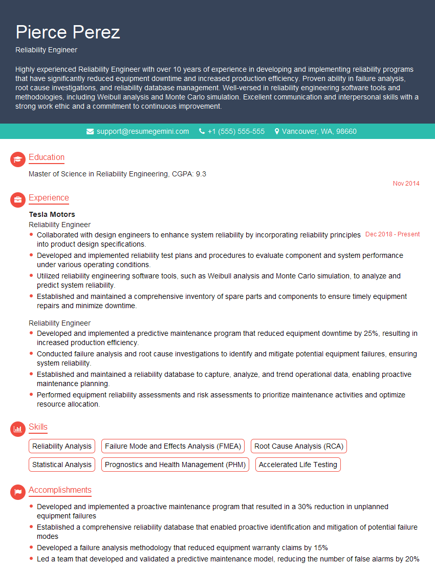
Reliability Engineer Resume Sample
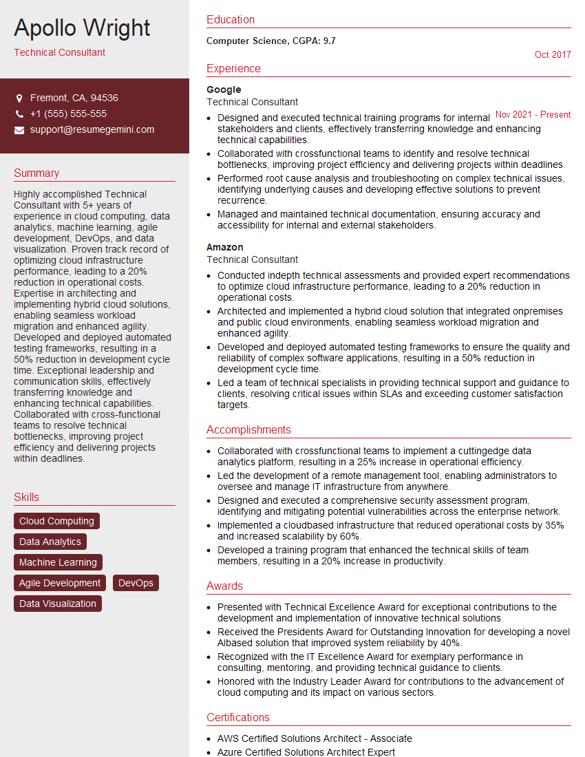
Technical Consultant Resume Sample
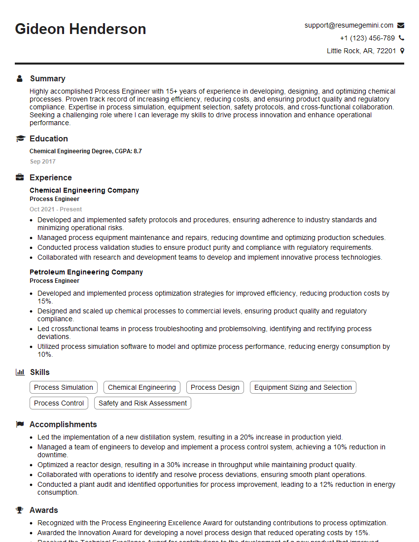
Process Engineer Resume Sample
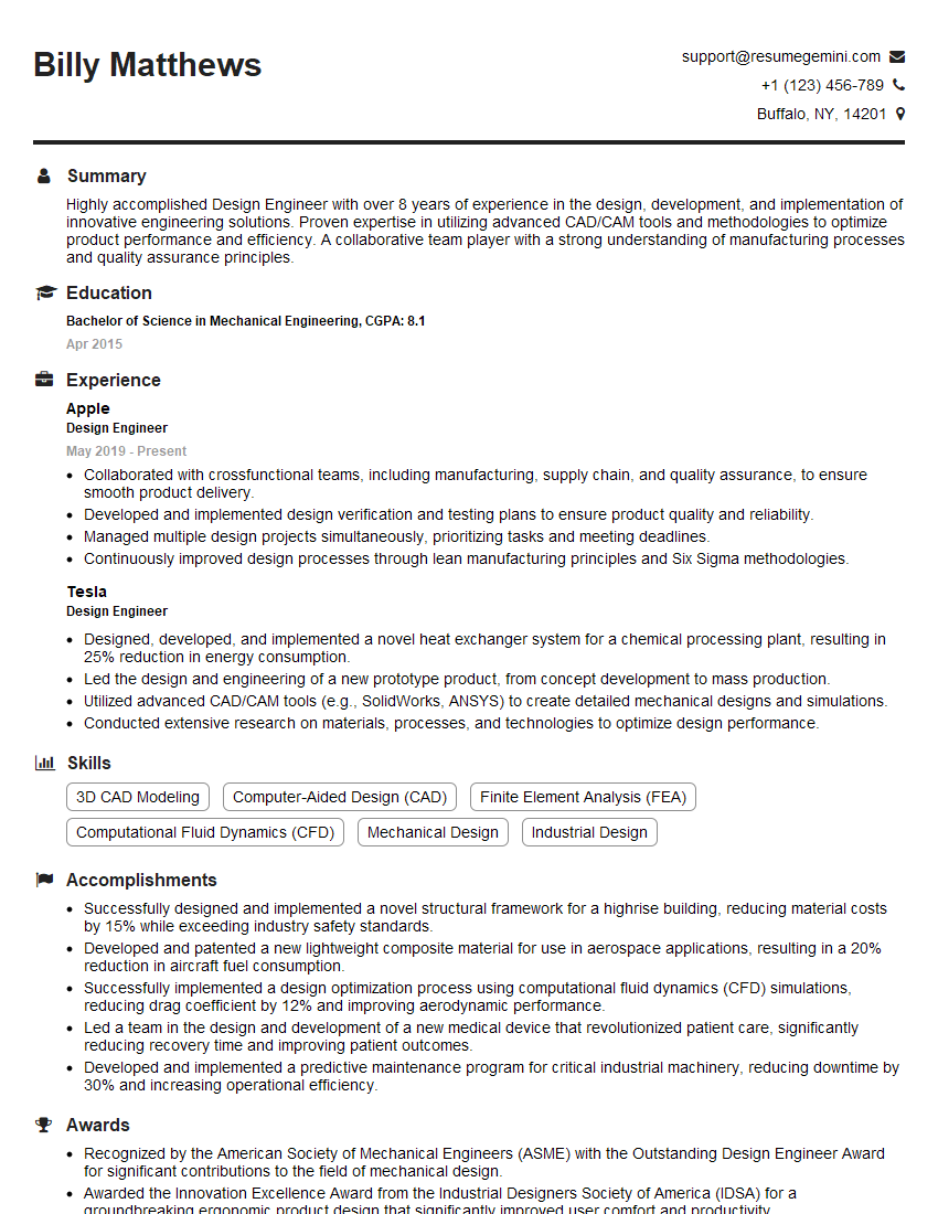
Design Engineer Resume Sample

Civil Engineer Resume Sample

Construction Engineer Resume Sample

Maintenance Engineer Resume Sample
Field Engineer Resume Sample

Instrumentation Engineer Resume Sample

Operations Engineer Resume Sample
Piping Designer Resume Sample
Mechanical Engineer Resume Sample

Control Systems Engineer Resume Sample

Drafter Resume Sample
- Project Manager
- Engineering Manager
- Project Engineer
- Reliability Engineer
- Technical Consultant
- Process Engineer
- Design Engineer
- Civil Engineer
- Construction Engineer
- Maintenance Engineer
- Field Engineer
- Instrumentation Engineer
- Operations Engineer
- Piping Designer
- Mechanical Engineer
- Control Systems Engineer
- Drafter
Explore more articles
Users Rating of Our Blogs
Share Your Experience
We value your feedback! Please rate our content and share your thoughts (optional).
What Readers Say About Our Blog
To the interviewgemini.com Webmaster.
Very helpful and content specific questions to help prepare me for my interview!
Thank you
To the interviewgemini.com Webmaster.
This was kind of a unique content I found around the specialized skills. Very helpful questions and good detailed answers.
Very Helpful blog, thank you Interviewgemini team.