Interviews are more than just a Q&A session—they’re a chance to prove your worth. This blog dives into essential Mechanical and Structural interview questions and expert tips to help you align your answers with what hiring managers are looking for. Start preparing to shine!
Questions Asked in Mechanical and Structural Interview
Q 1. Explain the difference between static and dynamic loading.
The key difference between static and dynamic loading lies in how the load is applied to a structure. Static loading involves a gradual application of a force that remains constant over time. Think of a building supporting its own weight – the load is relatively unchanging. The analysis is simpler, focusing on equilibrium conditions. Dynamic loading, on the other hand, involves forces that change rapidly in magnitude, direction, or both. This includes impacts, vibrations, and shocks. Imagine a bridge being hit by a moving vehicle or a building experiencing an earthquake. Analyzing dynamic loads requires considering inertia and the time-dependent nature of the forces, which significantly increases the complexity.
Example: A book resting on a table experiences static loading; a car crashing into a wall experiences dynamic loading. The latter requires a more sophisticated analysis because the forces change rapidly, potentially leading to much higher stresses and greater risk of failure than a static load of the same magnitude.
Q 2. Describe your experience with Finite Element Analysis (FEA).
I have extensive experience utilizing Finite Element Analysis (FEA) software, primarily ANSYS and Abaqus, throughout my career. My work has encompassed a wide range of applications, including structural analysis of buildings, bridges, and mechanical components. For example, I used FEA to optimize the design of a complex pressure vessel, ensuring it met safety requirements under extreme pressure and temperature conditions. This involved meshing the geometry, defining material properties, applying boundary conditions (constraints and loads), and interpreting the resulting stress, strain, and displacement data to identify potential weak points. In another project, I employed FEA to simulate the dynamic loading of a vehicle chassis during a crash test, helping to improve crashworthiness.
Beyond the technical application, my expertise also extends to validating FEA results through experimental testing and correlating numerical and experimental data. I’m proficient in choosing the appropriate element types and mesh densities depending on the specific problem to ensure accuracy and efficiency. This involves a deep understanding of the underlying mathematical principles, making sure the model truly reflects reality.
Q 3. How do you determine the factor of safety for a design?
The factor of safety (FOS) is a critical parameter in engineering design, ensuring that a structure or component can withstand loads greater than expected. It’s the ratio of the ultimate strength of a material to the allowable stress (or working stress) that is applied. The formula is simple: FOS = Ultimate Strength / Allowable Stress.
Determining the appropriate FOS involves several considerations: material properties, load uncertainties, environmental factors (temperature, corrosion), consequences of failure (safety risk), and design codes or industry standards. For instance, a bridge design requires a much higher FOS than a simple shelf because the consequences of bridge failure are catastrophic. In practice, different FOS values are specified based on these critical factors, ensuring adequate margins of safety. Industry standards and regulations often dictate minimum FOS values for different applications.
Example: If the ultimate tensile strength of steel is 500 MPa and the allowable stress is determined to be 50 MPa after considering all safety factors, then the factor of safety is 10 (500 MPa / 50 MPa = 10).
Q 4. What are the different types of structural failure modes?
Structural failure can occur in various ways. Some common modes include:
- Yielding: Permanent deformation of a material exceeding its elastic limit. Imagine bending a paperclip; once you pass its yield point, it won’t return to its original shape.
- Fracture: Complete separation of a material due to excessive stress. A broken bone is a prime example.
- Buckling: Sudden sideways failure of a slender component under compressive loading. Think of a thin column collapsing under its own weight.
- Fatigue: Progressive fracture caused by repeated cyclic loading. This is a common failure mode in bridges and aircraft subjected to continuous vibrations.
- Creep: Time-dependent deformation under sustained stress, particularly at high temperatures. This is a concern in power plant components.
- Corrosion: Degradation of material properties due to chemical or electrochemical reactions, weakening the structure and ultimately leading to failure.
Understanding these failure modes is crucial in selecting appropriate materials, designing robust geometries, and implementing preventative measures to ensure structural integrity.
Q 5. Explain the concept of stress and strain.
Stress is the internal force per unit area within a material that resists an externally applied load. It’s essentially how much the material is ‘fighting back’ against the load. The unit is usually Pascals (Pa) or megapascals (MPa). Imagine stretching a rubber band; the rubber band is experiencing internal stress.
Strain is the measure of deformation of a material in response to stress. It’s the change in length (or dimension) divided by the original length (or dimension), usually expressed as a dimensionless quantity or percentage. Continuing with the rubber band example, the stretching of the band represents strain.
The relationship between stress and strain is fundamental in material science, depicted by the stress-strain curve, which characterizes a material’s mechanical properties.
Q 6. What is the difference between yield strength and ultimate tensile strength?
Both yield strength and ultimate tensile strength are key parameters obtained from a material’s tensile test, representing its resistance to deformation and fracture. Yield strength is the stress at which a material begins to deform plastically (permanently). It’s the point beyond which the material will not return to its original shape once the load is removed. The 0.2% offset method is often used to define the yield strength.
Ultimate tensile strength is the maximum stress a material can withstand before it starts to fracture. It represents the material’s maximum load-bearing capacity. The ultimate tensile strength is always higher than the yield strength.
Example: Consider a steel bar undergoing a tensile test. The yield strength might be 250 MPa, indicating that permanent deformation begins at this stress level. The ultimate tensile strength might be 450 MPa, meaning the bar will fracture when the stress exceeds this value.
Q 7. Describe your experience with CAD software (e.g., SolidWorks, AutoCAD).
I am highly proficient in various CAD software packages, including SolidWorks, AutoCAD, and Creo Parametric. My experience encompasses the entire design process, from conceptual sketching and 3D modeling to detailed drafting and design analysis. I regularly use these tools for creating detailed engineering drawings, developing and optimizing 3D models of complex assemblies, and generating FEA models. For example, in a recent project, I used SolidWorks to design a new robotic arm, utilizing its simulation capabilities to optimize the arm’s strength and kinematic properties before manufacturing. In another instance, I leveraged AutoCAD to create detailed shop drawings for a structural steel fabrication project, ensuring accuracy and clarity for the manufacturing team.
My skills extend beyond the basics of modeling and drafting to include advanced techniques such as surface modeling, creating complex assemblies, and utilizing design automation tools to improve efficiency and reduce errors. I’m also well-versed in data management and version control within the CAD environment.
Q 8. How do you handle design changes during a project?
Handling design changes is crucial for project success. My approach involves a systematic process. First, I meticulously analyze the proposed change, assessing its impact on the overall design, budget, and schedule. This includes evaluating potential ripple effects across different components and systems. Next, I collaborate closely with the project team, including engineers, clients, and manufacturers, to discuss the feasibility and implications of the modification. This collaborative effort often involves brainstorming alternative solutions and evaluating trade-offs. Once a decision is made, I update the design documentation, ensuring all relevant stakeholders have access to the revised plans. Crucially, I also document the reasons for the change and any associated risk mitigation strategies. A recent project involved a late-stage change request to a bridge design. By thoroughly evaluating the impact and implementing a revised reinforcement strategy, we successfully minimized delays and cost overruns. The key is transparency and proactive communication throughout the process.
Q 9. Explain your understanding of fatigue analysis.
Fatigue analysis is the process of determining the lifespan of a component under cyclic loading. Imagine repeatedly bending a paperclip – eventually, it’ll break. This is fatigue failure. In engineering, components are constantly subjected to fluctuating stresses, and fatigue analysis predicts when failure might occur. This involves analyzing stress cycles (repeated loading), stress concentration factors (where stresses are higher), material properties (fatigue strength), and environmental factors. Several methods exist, including S-N curves (relating stress amplitude to the number of cycles to failure) and finite element analysis (FEA) to simulate the stress distribution under cyclic loading. For example, in designing aircraft wings, fatigue analysis is critical to ensure the wings can withstand millions of cycles of loading and unloading during the aircraft’s lifespan. Ignoring fatigue can lead to catastrophic failures, so it’s a fundamental aspect of design for safety-critical applications.
Q 10. What are the different types of beams and their applications?
Beams are structural elements that primarily resist transverse loads (loads perpendicular to their length). Several types exist, each with its own applications:
- Simply Supported Beam: Supported at both ends. Used commonly in bridges and floor joists. Think of a plank resting on two sawhorses.
- Cantilever Beam: Fixed at one end and free at the other. Used in balconies, diving boards, and some types of aircraft wings.
- Overhanging Beam: Extends beyond its supports. Found in building structures with cantilevered sections.
- Fixed Beam: Fixed at both ends, providing greater resistance to deflection. Often used in building columns.
- Continuous Beam: Extends over multiple supports. Common in bridges and multi-span structures.
The choice of beam type depends on the loading conditions, support constraints, and desired deflection limits. For example, a cantilever beam might be suitable for a balcony due to its ability to support weight from only one end, but its deflection needs to be carefully considered.
Q 11. How do you select appropriate materials for a given application?
Material selection is a critical aspect of design. It hinges on several factors: strength, stiffness, weight, cost, corrosion resistance, and manufacturability. I use a systematic approach involving comparing candidate materials based on these criteria. For instance, if I’m designing a lightweight aircraft component, I’d likely consider aluminum alloys for their high strength-to-weight ratio. However, if corrosion resistance is paramount, I might choose a stainless steel or a composite material. Often, there’s a trade-off; a stronger material might be heavier or more expensive. Material databases and engineering handbooks provide the necessary properties for this comparison. Software tools can also be used to simulate material behavior under various loading conditions. For example, selecting a material for a prosthetic limb would require considering biocompatibility, strength, and flexibility to ensure patient comfort and functionality. The process is iterative, often involving testing and refinement.
Q 12. Describe your experience with manufacturing processes.
My experience encompasses various manufacturing processes, including machining (milling, turning, drilling), casting (sand casting, investment casting), forging, welding (MIG, TIG, spot welding), and additive manufacturing (3D printing). I understand the capabilities and limitations of each process, its suitability for different materials and geometries, and its impact on cost and quality. For example, I’ve used CNC machining for creating high-precision parts and casting for creating complex shapes. Additive manufacturing offers great design flexibility, but its limitations in material choice and surface finish need to be considered. Understanding manufacturing processes allows me to design parts that are not only functionally sound but also manufacturable efficiently and cost-effectively. A recent project involved designing a component optimized for investment casting due to its intricate geometry, resulting in significant cost savings.
Q 13. Explain the concept of buckling in structural elements.
Buckling refers to a sudden, large lateral deformation of a structural element under compressive load. Think of a slender column – when compressed beyond a certain limit, it will suddenly bend sideways rather than continue to shorten. This critical load is called the buckling load, and it depends on the geometry (length, cross-sectional area, shape) and material properties (Young’s modulus) of the column. Euler’s formula provides an estimate of the buckling load for slender columns. Preventing buckling is vital; it often leads to complete structural failure. Design strategies include increasing the column’s cross-sectional area, using a material with a higher Young’s modulus, shortening its length, or adding lateral supports. For example, in designing tall buildings, engineers must account for the buckling of columns under their own weight and external loads, making the selection of appropriate cross-sections and ensuring stability of vital importance.
Q 14. How do you ensure the quality and reliability of your designs?
Ensuring design quality and reliability involves a multifaceted approach. First, I rigorously adhere to engineering standards and best practices throughout the design process. This includes performing thorough calculations, simulations, and analyses to verify that the design meets all requirements. Next, I employ robust quality control measures during the manufacturing process, including material inspections, dimensional checks, and non-destructive testing (NDT) techniques like ultrasonic testing or radiography to detect hidden flaws. Documentation is also key; I maintain detailed records of all design calculations, simulations, and test results. Furthermore, I leverage design reviews to involve other experts in validating the design and identifying potential issues before they become problems. For example, in a recent bridge project, we used advanced FEA simulations and rigorous quality control during construction, ensuring the bridge’s long-term structural integrity and safety. Continuous monitoring and feedback mechanisms are crucial for maintaining quality and reliability throughout the project life cycle.
Q 15. What are your preferred methods for stress analysis?
Stress analysis is crucial for ensuring the structural integrity of any component or system. My preferred methods depend heavily on the complexity of the structure and the available resources. For simpler geometries and loading conditions, I often utilize hand calculations using established formulas and stress concentration factors. This allows for a quick understanding of the dominant stress patterns and a preliminary assessment of safety.
For more complex geometries or loading, I rely heavily on Finite Element Analysis (FEA) software such as ANSYS or Abaqus. FEA allows for a highly detailed and accurate stress analysis, considering factors like material properties, boundary conditions, and various load cases. I’m proficient in mesh generation, boundary condition definition, and interpreting the resulting stress and deformation patterns. A key aspect is validating the FEA results through comparison with simplified analytical solutions or experimental data, ensuring accuracy and reliability.
Finally, I also utilize experimental stress analysis techniques, such as strain gauge measurements, when appropriate. This is particularly valuable for validating FEA models or investigating complex real-world scenarios where analytical or numerical methods might fall short. The choice of method is always driven by the project’s specific requirements, budget, and timeframe.
Career Expert Tips:
- Ace those interviews! Prepare effectively by reviewing the Top 50 Most Common Interview Questions on ResumeGemini.
- Navigate your job search with confidence! Explore a wide range of Career Tips on ResumeGemini. Learn about common challenges and recommendations to overcome them.
- Craft the perfect resume! Master the Art of Resume Writing with ResumeGemini’s guide. Showcase your unique qualifications and achievements effectively.
- Don’t miss out on holiday savings! Build your dream resume with ResumeGemini’s ATS optimized templates.
Q 16. Describe your experience with vibration analysis.
My experience with vibration analysis spans various techniques and applications. I’ve worked extensively on modal analysis, identifying the natural frequencies and mode shapes of structures. This is crucial for avoiding resonance and ensuring the structural integrity under dynamic loads. I’ve used both experimental methods, like impact testing with accelerometers, and FEA simulations to perform modal analysis.
I’m also experienced in harmonic analysis, assessing the structural response to periodic excitations like rotating machinery. This involves determining the amplitude and phase of vibrations at different frequencies. Understanding this allows for designing effective vibration isolation systems or predicting fatigue life under cyclic loading.
Furthermore, I’ve worked with random vibration analysis, modeling the effects of complex, unpredictable excitations like earthquakes or wind loads. This usually involves spectral analysis techniques and statistical approaches to predict the probability of failure.
In practice, I’ve applied these techniques to everything from analyzing the vibration of a turbine blade to mitigating the seismic response of a building structure. My approach is always to start with a thorough understanding of the system’s dynamics, choose the appropriate analytical or experimental techniques, and meticulously interpret the results to offer practical solutions.
Q 17. How do you handle conflicting project requirements?
Conflicting project requirements are a common reality in engineering. My approach involves a structured process of prioritization and compromise. I begin by clearly documenting all requirements, identifying conflicts and their potential impact. Then, I engage in open communication with all stakeholders, including clients, designers, and other engineers. We collaboratively evaluate the importance of each requirement, considering factors like cost, schedule, and performance implications.
Sometimes, this involves trade-off analysis, quantifying the impact of compromises on different aspects of the project. For example, if a deadline conflict arises between aesthetics and functionality, a quantitative analysis might determine that minor aesthetic compromises are acceptable if they ensure structural integrity. Ultimately, the goal is to find a solution that meets the most critical requirements while minimizing compromises on the others. Thorough documentation of decisions and compromises throughout this process is crucial for transparency and accountability.
Q 18. Explain your understanding of thermal stress.
Thermal stress arises from temperature gradients within a structure. When a material is heated or cooled unevenly, it tries to expand or contract differently in different regions. This leads to internal stresses that can cause deformation or even failure. Imagine heating one end of a metal rod; the hotter end tries to expand more than the cooler end, resulting in compressive stress at the hot end and tensile stress at the cooler end.
The magnitude of thermal stress depends on several factors, including the material’s coefficient of thermal expansion (CTE), the temperature difference, and the geometry of the structure. The formula for thermal stress is relatively straightforward: σ = EαΔT, where σ is the stress, E is the Young’s modulus, α is the CTE, and ΔT is the temperature difference. However, the actual stress distribution in a real structure can be quite complex and might require FEA for accurate prediction.
In practice, managing thermal stress often involves careful design considerations, such as using materials with low CTEs, providing sufficient space for expansion, or incorporating thermal barriers. I have utilized these principles in designing components for high-temperature applications, such as engines and furnaces, where thermal stress management is crucial for ensuring longevity and preventing catastrophic failures.
Q 19. Describe your experience with different types of joints.
My experience encompasses a wide range of joints, each with its own strengths and weaknesses. I’m familiar with bolted joints, which are widely used due to their ease of assembly and disassembly. However, I’m well aware of the importance of proper bolt tightening to avoid issues like fatigue failure. Welded joints offer excellent strength and rigidity but require careful attention to welding procedures to ensure sound welds and avoid defects. I understand different welding techniques and their suitability for various materials and applications.
I also have experience with riveted joints, commonly used in structural steel applications. These require meticulous design and installation to ensure proper load transfer. Adhesive bonding is another method I’ve used, particularly for joining dissimilar materials or creating lightweight structures. Finally, I’m familiar with various mechanical joints such as pins, keys, and splines, each appropriate for specific applications. The selection of a suitable joint depends heavily on the specific application’s loading conditions, environmental factors, required strength, and ease of assembly.
Q 20. How do you ensure compliance with relevant building codes and standards?
Compliance with building codes and standards is paramount in my work. I meticulously review and incorporate all relevant codes and regulations, such as the International Building Code (IBC) or Eurocodes, depending on the project’s location and type. I ensure the design meets all relevant safety, structural, and performance requirements.
My process involves thoroughly studying the applicable codes and standards, identifying all requirements, and incorporating them into the design from the outset. I use design software that allows for code compliance checking and generate design documentation that clearly demonstrates adherence to all requirements. Regular reviews and checks are performed during all project phases to ensure continued compliance.
Beyond simply meeting minimum requirements, I actively seek opportunities to exceed code requirements, delivering designs that are not only safe and compliant but also robust and resilient. This proactive approach is a significant part of my commitment to building safe and reliable structures.
Q 21. Explain your understanding of creep and relaxation.
Creep is the time-dependent deformation of a material under sustained stress at elevated temperatures. Imagine a metal component under constant load in a hot environment – it will gradually deform over time. This is creep. The rate of creep depends on factors like temperature, stress level, and material properties.
Relaxation is the opposite; it’s the time-dependent decrease in stress under constant strain at elevated temperatures. If you hold a material at a fixed length at a high temperature, the stress required to maintain that length will gradually decrease over time. This is relaxation. Both creep and relaxation are significant considerations in high-temperature applications, such as gas turbines and power plant components.
Understanding these phenomena is crucial for designing structures with long-term stability and reliability at elevated temperatures. This often requires specialized materials, design techniques to minimize stresses, and detailed analysis using time-dependent constitutive models within FEA software. Ignoring creep and relaxation can lead to unexpected deformations, component failure, and ultimately, safety risks.
Q 22. What are your experience with different types of structural steel?
My experience with structural steel encompasses a wide range of grades and applications. I’ve worked extensively with common structural steels like A36, A992, and A572, understanding their yield strengths, tensile strengths, and ductility. These grades are frequently used in building frameworks, bridges, and other large-scale structures. Beyond these standard grades, I have experience with higher-strength steels, such as those used in high-rise buildings or specialized applications requiring greater load-bearing capacity. For example, I’ve worked on a project using high-strength steel to minimize the weight and size of a bridge girder, improving both efficiency and aesthetics.
Furthermore, my knowledge extends to weathering steels (like COR-TEN), which develop a protective patina that reduces maintenance needs. I also understand the properties and applications of various steel shapes, including wide-flange beams (W-shapes), channels (C-shapes), angles (L-shapes), and pipes, selecting the most suitable shape and grade based on the specific design requirements and loading conditions. Proper understanding of steel’s behavior under various loading conditions, including yielding, buckling, and fatigue, is critical for safe and efficient design.
Q 23. How do you approach solving an indeterminate structural problem?
Solving an indeterminate structural problem requires a systematic approach. Unlike determinate structures where equilibrium equations alone suffice, indeterminate structures have more unknowns than equilibrium equations. This means we need additional equations derived from compatibility conditions (geometric constraints and material behavior).
My approach involves the following steps:
- Clearly define the structure and loading: A detailed understanding of supports, loads, and material properties is crucial. Free-body diagrams are essential.
- Determine the degree of indeterminacy: Calculate the number of extra unknowns. This determines the additional equations needed.
- Select an appropriate method: Several methods can be employed: the force method (using compatibility equations to solve for redundants), the displacement method (using stiffness matrices and solving for displacements), or matrix methods employing software.
- Solve the equations: This usually involves solving a system of simultaneous equations, which can be done manually for simple cases or using software packages like MATLAB or specialized FEA software for complex structures.
- Verify the solution: Checking the equilibrium and compatibility conditions is critical to ensure the solution’s accuracy. Internal forces and stresses are then calculated.
For instance, a continuous beam supported at multiple points is an indeterminate structure. I would use the displacement method, often employing software to solve the resulting stiffness matrix equation for the displacement at each support. The resulting displacements then allow calculation of the internal reactions and moments throughout the beam.
Q 24. Describe your experience with non-linear finite element analysis.
My experience with non-linear finite element analysis (FEA) is substantial. I understand that linear FEA assumptions break down when dealing with large deformations, material non-linearity (plasticity, hyperelasticity), or contact problems. Non-linear FEA allows me to model these complex behaviors accurately.
I have used non-linear FEA extensively in several projects:
- Modeling large deflection of beams and plates: For instance, analyzing the behavior of a flexible cantilever beam under a large point load, where the beam’s geometry changes significantly.
- Predicting failure in components: Simulating plastic deformation and fracture initiation to assess the strength and stability of a structural component under extreme loads.
- Analyzing contact problems: Modeling the interaction of different structural elements—for example, bolts in a connection or the interaction between a structure and the ground.
Software packages like Abaqus and ANSYS are vital tools in my workflow, enabling me to refine meshes, choose appropriate material models, and interpret the complex results from non-linear analyses. I am adept at selecting appropriate solution techniques and interpreting convergence characteristics to ensure results are accurate and meaningful. This detailed analysis allows me to optimize designs, improve safety factors and minimize material usage.
Q 25. Explain the concept of moment of inertia and its significance.
The moment of inertia (I), also called the second moment of area, is a geometrical property of a cross-sectional shape that quantifies its resistance to bending. Imagine trying to twist a long, thin rod versus a thick, short one – the thicker rod resists twisting much more effectively. This is directly related to its moment of inertia.
In structural analysis, a larger moment of inertia indicates a greater resistance to bending. The equation varies depending on the shape. For a simple rectangular section:
I = (b*h^3)/12where ‘b’ is the width and ‘h’ is the height.
The significance lies in its use in the flexure formula:
σ = My/Iwhere σ is bending stress, M is bending moment, y is the distance from the neutral axis, and I is the moment of inertia. This formula allows engineers to determine the stresses in a beam subjected to bending. A larger I leads to lower bending stresses for the same bending moment, indicating a stronger, more resistant beam. This is crucial for ensuring structural integrity and preventing failure.
Q 26. How do you evaluate the stability of a structure?
Evaluating the stability of a structure involves assessing its ability to resist collapse under various loading conditions. This encompasses both static and dynamic stability. My approach involves several key considerations:
- Buckling analysis: Slender structural members are susceptible to buckling, a sudden failure under compressive loads. I use methods like Euler’s formula for simple columns or more sophisticated FEA for complex structures to determine critical buckling loads.
- Overall stability: This involves checking the stability of the entire structure, considering all loads and supports. This often necessitates assessing the interaction between different structural elements.
- Foundation analysis: The soil’s bearing capacity and the foundation design directly influence overall structural stability. I ensure adequate foundation design to support the structure and prevent settlement or failure.
- Dynamic analysis: The structure’s response to dynamic loads (wind, earthquakes) is crucial. This often requires modal analysis and time-history analysis to determine dynamic stresses and displacements.
- Material properties: Understanding the material’s strength, stiffness, and behavior under stress is fundamental. Accounting for material degradation over time is also important.
For example, when designing a tall building, stability is paramount. I would use sophisticated FEA software, incorporating wind loads and seismic effects, to model and analyze potential failure mechanisms. Careful consideration of foundation design, material selection and structural detailing would then be vital to ensure stability and safety.
Q 27. Describe your understanding of seismic design considerations.
Seismic design considerations are crucial for structures in earthquake-prone regions. The goal is to minimize damage and ensure life safety during an earthquake. My understanding of seismic design encompasses several aspects:
- Seismic zoning and ground motion: Determining the appropriate seismic design parameters based on the location’s seismic hazard. This involves understanding various ground motion parameters like peak ground acceleration (PGA) and spectral acceleration.
- Structural analysis: Using dynamic analysis techniques like response spectrum analysis or time-history analysis to determine the structure’s response to seismic excitation. This involves modeling the structure’s dynamic properties and applying appropriate earthquake ground motions.
- Structural design: Implementing strategies to enhance the structure’s resistance to seismic loads, including ductile detailing, base isolation, and energy dissipation devices. Ductile detailing aims to allow controlled yielding in critical sections before major failure, dissipating seismic energy through plastic deformation. Base isolation isolates the building from the ground motion, reducing transmitted forces.
- Code compliance: Ensuring that the design meets or exceeds the requirements of relevant building codes and standards related to seismic design.
In a practical sense, I’ve worked on projects where we’ve incorporated base isolation systems into building designs to minimize the impact of seismic ground motion, dramatically improving resilience. I’ve also implemented energy-dissipating systems, allowing structural elements to yield in a controlled manner during an earthquake, preventing catastrophic failure.
Q 28. What are your experience with composite materials?
My experience with composite materials in structural applications is growing. These materials, combining two or more constituent materials with significantly different properties, offer unique advantages in terms of strength-to-weight ratio and stiffness.
I’ve worked with several types of composites, including:
- Fiber-reinforced polymers (FRP): These materials, such as carbon fiber reinforced polymer (CFRP) and glass fiber reinforced polymer (GFRP), offer high strength and stiffness, low weight, and corrosion resistance. I’ve used them for strengthening existing structures (retrofitting), designing lightweight components, and creating high-performance structures.
- Concrete composites: Adding fibers to concrete, like steel fibers or synthetic fibers, enhances its strength and toughness, improving its resistance to cracking and impact damage. This is particularly useful in harsh environments or for structures subjected to dynamic loads.
The design of composite structures requires a deep understanding of material behavior under various loading conditions, including the interaction between constituent materials and the effect of different failure mechanisms. It’s often necessary to employ advanced analytical techniques and FEA simulations to accurately predict their behavior. For example, I’ve utilized FEA to model the stress distribution in a CFRP strengthened beam, accounting for the nonlinear behavior of both the FRP and the concrete substrate to ensure structural integrity.
Key Topics to Learn for Mechanical and Structural Interviews
- Statics and Dynamics: Understanding forces, moments, equilibrium, and motion is fundamental. Consider practical applications like analyzing bridge stability or designing shock absorbers.
- Strength of Materials: Master stress, strain, and material properties. Think about how this knowledge applies to selecting appropriate materials for a building’s structural components or designing a durable machine part.
- Fluid Mechanics: Explore concepts like pressure, flow, and viscosity. Consider applications in designing efficient piping systems or analyzing aerodynamic forces on aircraft.
- Thermodynamics: Understand heat transfer, energy conversion, and thermodynamic cycles. This is crucial for designing efficient engines or HVAC systems.
- Machine Design: Learn about mechanisms, gears, and power transmission. Think about designing robotic arms or optimizing manufacturing processes.
- Finite Element Analysis (FEA): Familiarize yourself with this powerful simulation tool used extensively in structural and mechanical engineering. Understand its applications in stress analysis and design optimization.
- Material Selection and Failure Analysis: Develop a strong understanding of various materials’ properties and how they relate to potential failure modes. Learn to analyze failures and propose solutions.
- Manufacturing Processes: Gain familiarity with common manufacturing techniques like casting, machining, and welding, understanding their implications on design and cost.
- Structural Analysis: Understand different methods for analyzing structures like trusses, beams, and frames under various loading conditions.
Next Steps
Mastering Mechanical and Structural engineering principles opens doors to exciting and impactful careers in various industries. To maximize your job prospects, a well-crafted, ATS-friendly resume is crucial. ResumeGemini can help you create a professional and effective resume that highlights your skills and experience. We offer examples of resumes tailored specifically to Mechanical and Structural engineering roles to guide you through the process. Invest time in building a strong resume – it’s your first impression on potential employers.
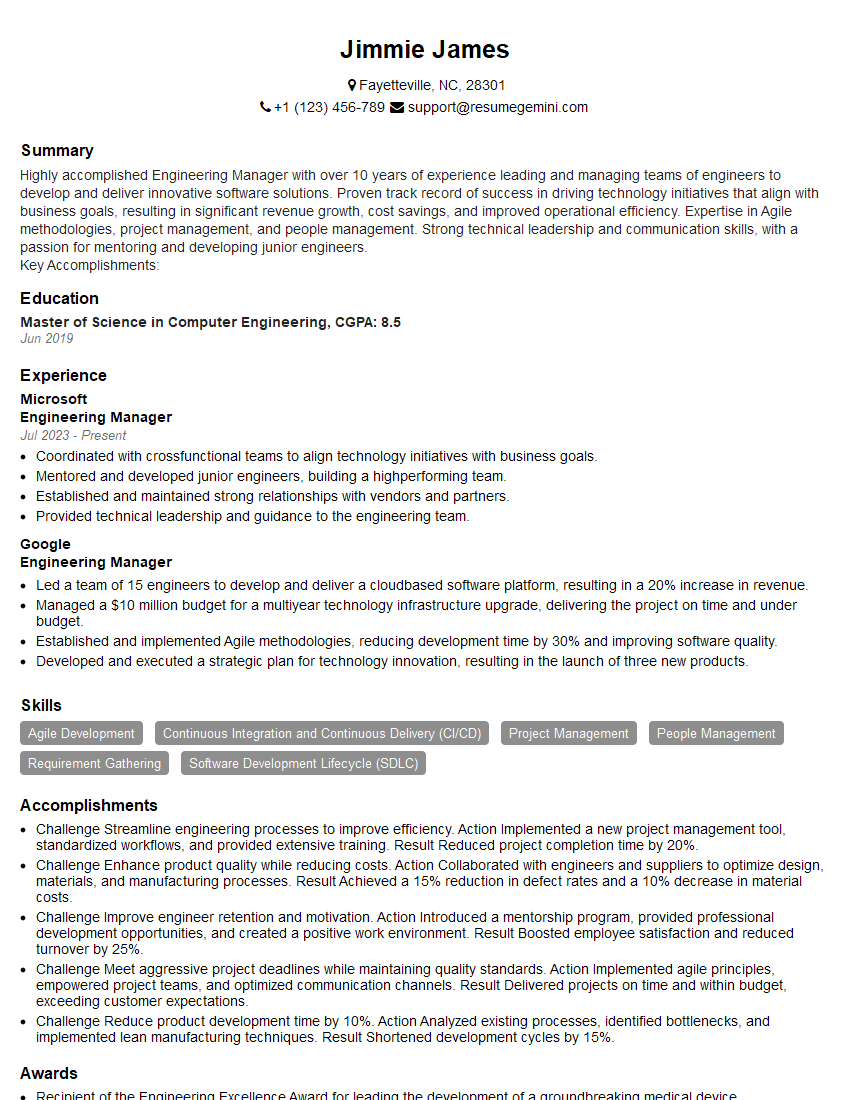
Engineering Manager Resume Sample
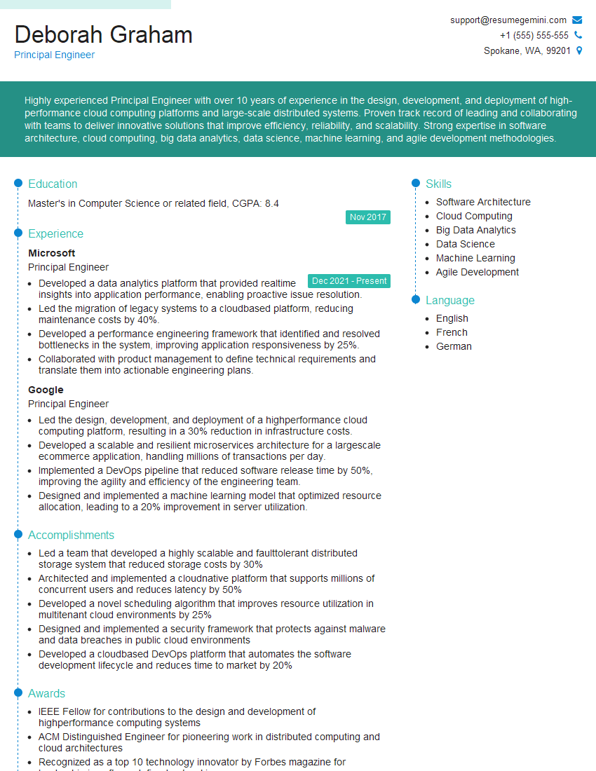
Principal Engineer Resume Sample
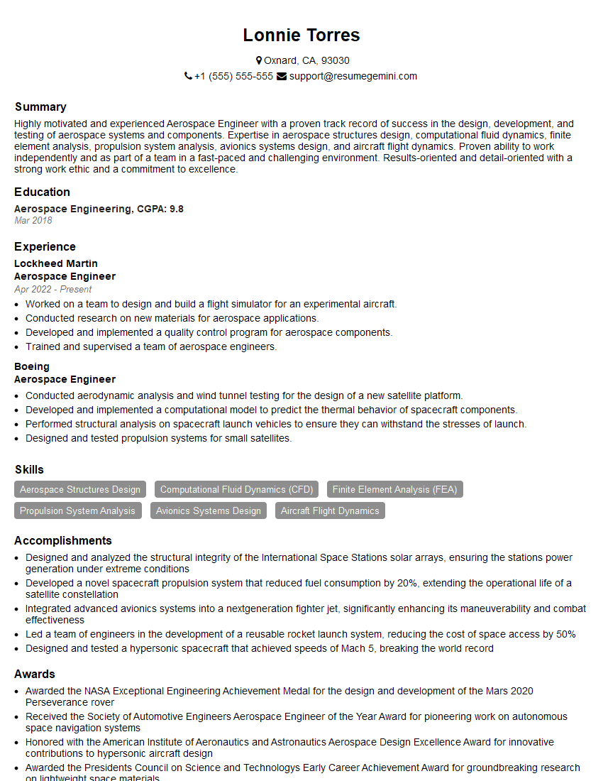
Aerospace Engineer Resume Sample
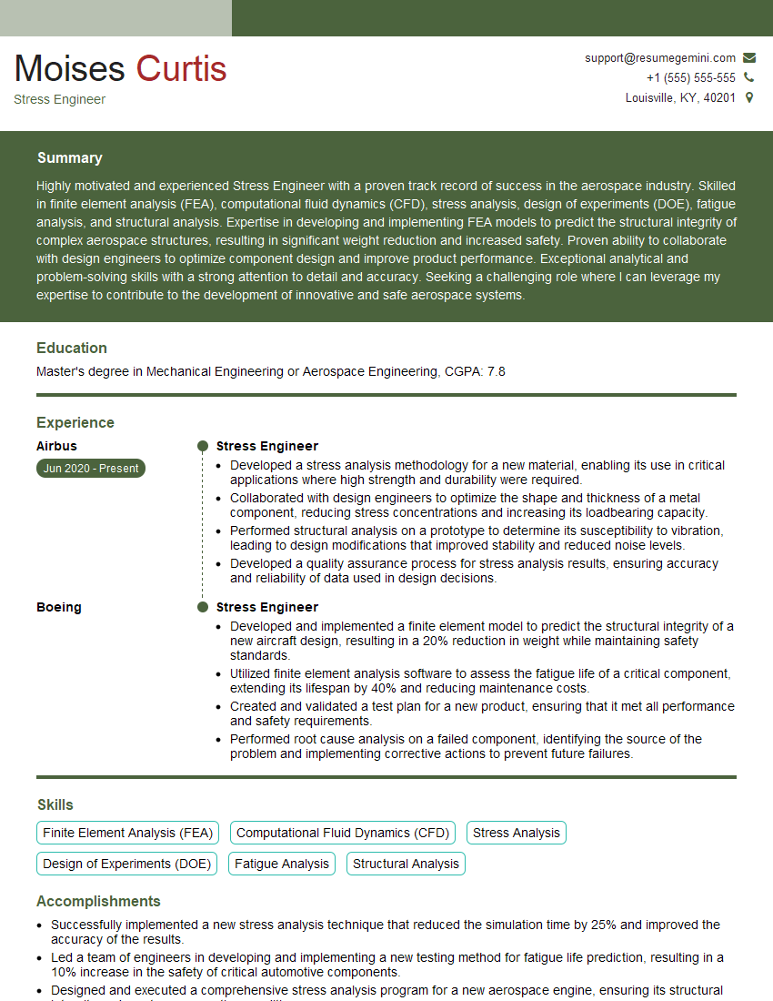
Stress Engineer Resume Sample
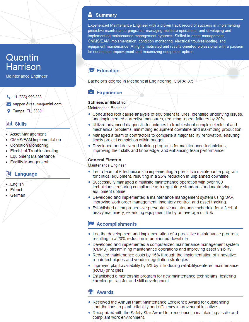
Maintenance Engineer Resume Sample
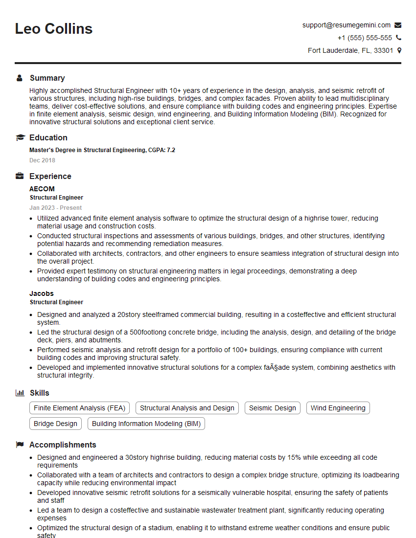
Structural Engineer Resume Sample
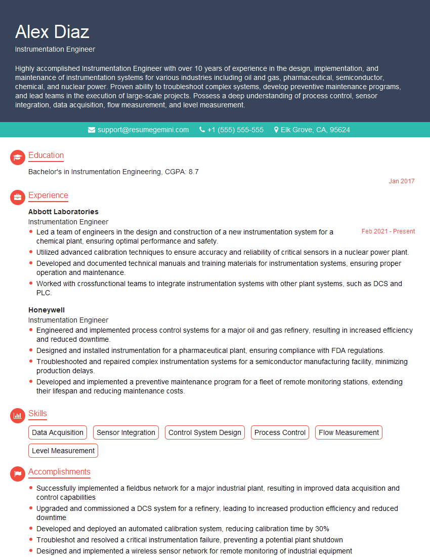
Instrumentation Engineer Resume Sample
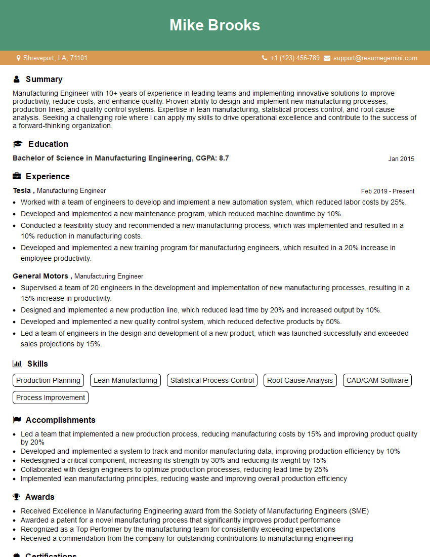
Manufacturing Engineer Resume Sample
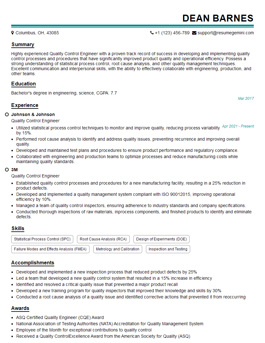
Quality Control Engineer Resume Sample
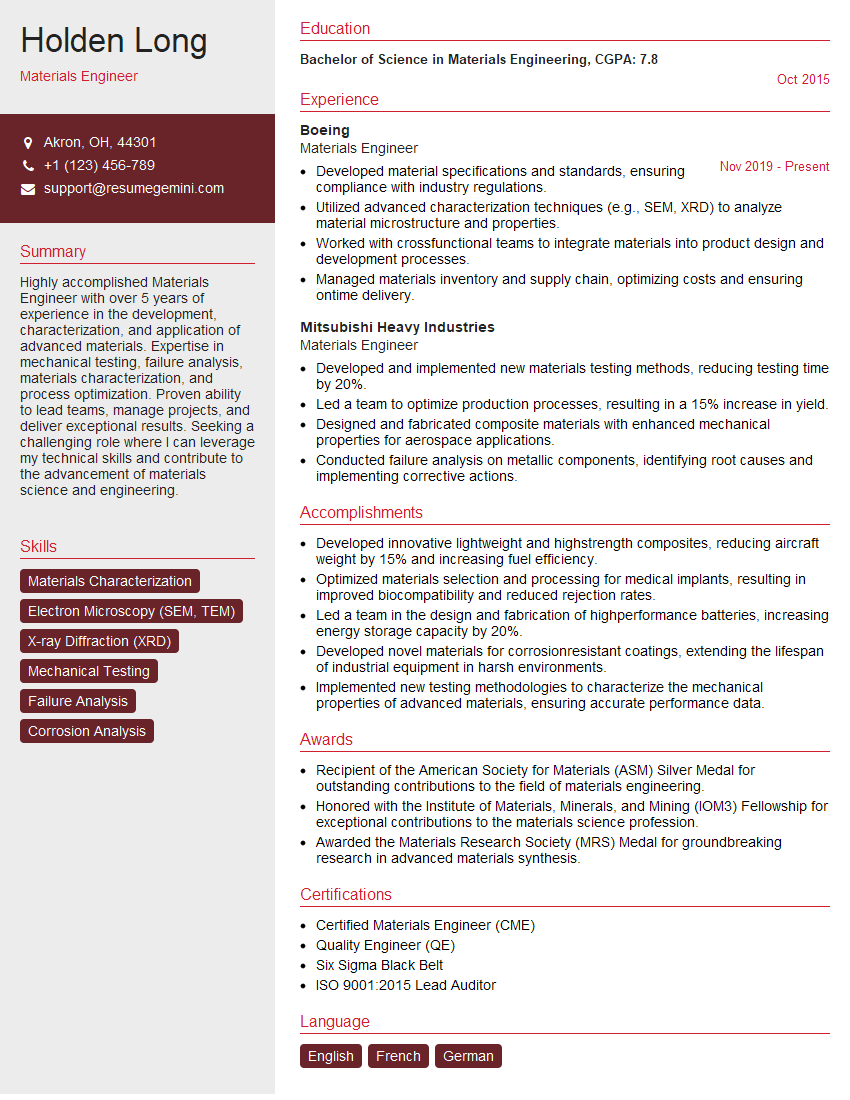
Materials Engineer Resume Sample
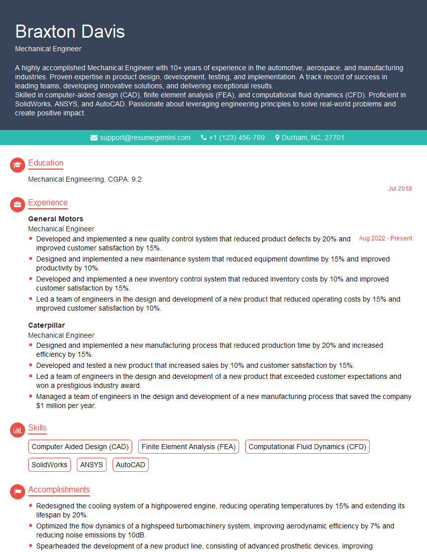
Mechanical Engineer Resume Sample
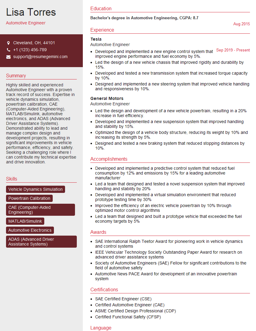
Automotive Engineer Resume Sample
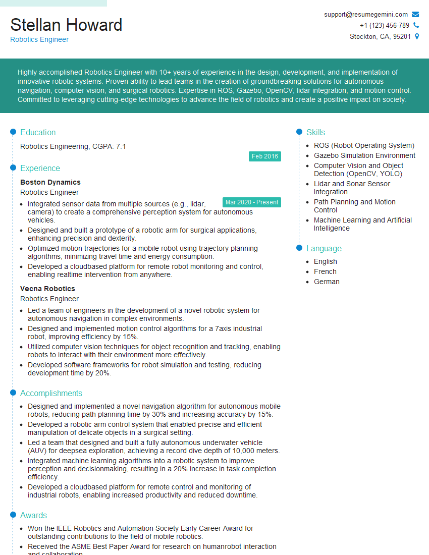
Robotics Engineer Resume Sample
Explore more articles
Users Rating of Our Blogs
Share Your Experience
We value your feedback! Please rate our content and share your thoughts (optional).
What Readers Say About Our Blog
To the interviewgemini.com Webmaster.
Very helpful and content specific questions to help prepare me for my interview!
Thank you
To the interviewgemini.com Webmaster.
This was kind of a unique content I found around the specialized skills. Very helpful questions and good detailed answers.
Very Helpful blog, thank you Interviewgemini team.