Every successful interview starts with knowing what to expect. In this blog, we’ll take you through the top Capacitor Bank Operations interview questions, breaking them down with expert tips to help you deliver impactful answers. Step into your next interview fully prepared and ready to succeed.
Questions Asked in Capacitor Bank Operations Interview
Q 1. Explain the principle of power factor correction using capacitor banks.
Power factor correction using capacitor banks improves the efficiency of electrical systems by reducing the reactive power component of the load. Inductive loads, like motors and transformers, consume reactive power, which doesn’t contribute to actual work but increases current flow. This higher current leads to increased energy losses in cables and equipment. Capacitor banks generate reactive power, effectively canceling out the reactive power consumed by the inductive loads. This results in a higher power factor, closer to 1, meaning a larger portion of the total current is active power, performing useful work.
Think of it like this: Imagine pushing a heavy box across a floor. The reactive power is like pushing against friction – you’re exerting effort, but not actually moving the box forward. The capacitor bank is like adding a helpful force that counteracts the friction, allowing you to push the box more efficiently.
Q 2. Describe different types of capacitor banks and their applications.
Capacitor banks come in various types, each suited to different applications:
- Fixed Capacitor Banks: These are the simplest type, consisting of permanently connected capacitors. They are ideal for relatively constant loads with stable power factor requirements, like lighting loads in a factory.
- Switched Capacitor Banks: These banks offer multiple capacitor steps that can be switched in or out to adjust the reactive power compensation based on load variations. This is common in industrial settings where the load fluctuates significantly throughout the day.
- Automatic Power Factor Correction (APFC) Systems: These sophisticated systems automatically adjust the capacitor bank size based on real-time power factor measurements. They provide optimal power factor correction and are suitable for highly dynamic loads or those with unpredictable power demand.
- Harmonic Filter Banks: These are specialized capacitor banks designed to mitigate harmonic distortions in the power system. Harmonics are undesirable voltage and current waveforms caused by non-linear loads (like rectifiers and variable-frequency drives) that can damage equipment. These filters incorporate specific capacitor and inductor configurations to suppress the harmonics.
The choice depends on factors such as load characteristics, cost considerations, and desired level of automation.
Q 3. How do you determine the appropriate size of a capacitor bank for a specific load?
Determining the appropriate capacitor bank size requires careful calculation and analysis of the load’s characteristics. The primary factor is the existing power factor and the desired power factor improvement. The following steps are usually involved:
- Measure the load’s current and power factor: This is done using power quality analyzers to determine the existing reactive power (Q).
- Determine the desired power factor: Usually, a target power factor of 0.95 or higher is aimed for. This value depends on utility company regulations and cost-benefit analysis.
- Calculate the required reactive power compensation (Qc): Formulas based on power triangle relationships are used. A simplified approach can use the formula:
Qc = P * (tan(θinitial) - tan(θdesired))where P is the real power, θinitial is the initial power factor angle, and θdesired is the desired power factor angle. - Select the appropriate capacitor size: Based on the calculated Qc and the available capacitor ratings, the number and size of capacitors are determined. It’s crucial to consider voltage ratings and other specifications to ensure compatibility with the system.
- Verify with simulations: Software simulations allow for more in-depth analysis and ensure optimal performance and stability.
Remember to always account for safety margins and potential future load increases.
Q 4. What are the safety precautions involved in working with capacitor banks?
Working with capacitor banks requires strict adherence to safety procedures because of the high voltages and stored energy. Key precautions include:
- Lockout/Tagout Procedures: Always lock out and tag out the power supply before any work is performed on the capacitor bank to prevent accidental energization.
- Personal Protective Equipment (PPE): Use appropriate PPE, including safety glasses, insulated gloves, and safety shoes.
- Grounding: Ensure proper grounding of the capacitor bank to prevent electrical shocks.
- Discharge Capacitors: Before performing any maintenance or repair, discharge the capacitors completely using a certified discharge tool. Never rely on visual inspection alone, as residual charge can be dangerous.
- Proper Training: All personnel working with capacitor banks should receive adequate training on safety procedures and emergency response.
Ignoring these safety measures can result in severe electrical shock, burns, or even fatalities.
Q 5. Explain the process of installing and commissioning a capacitor bank.
Installing and commissioning a capacitor bank involves several steps:
- Site Preparation: Ensure proper space and adequate ventilation are available for the capacitor bank. Consider accessibility for maintenance.
- Mounting and Wiring: Mount the capacitor bank securely and connect the wiring according to the manufacturer’s instructions, ensuring proper grounding and protection devices are in place.
- Testing and Commissioning: After installation, thoroughly test the capacitor bank, including insulation resistance, capacitance, and voltage ratings. This ensures correct functionality and safety before energization.
- Protection Relay Settings: Configure the protection relays appropriately to prevent overcurrent, overvoltage, and other fault conditions. This is a crucial aspect of safe and reliable operation.
- Performance Monitoring: After commissioning, regularly monitor the performance of the capacitor bank to detect any anomalies and ensure optimal operation. Data loggers and SCADA systems can be used for effective monitoring.
This process ensures that the capacitor bank is correctly integrated into the electrical system and operates safely and efficiently.
Q 6. How do you troubleshoot common problems in capacitor bank operation?
Troubleshooting capacitor bank problems often involves systematic investigation:
- Reduced Power Factor Improvement: This could indicate capacitor failure, incorrect sizing, or increased harmonic distortion. Check the capacitor’s capacitance and voltage ratings. Analyze the harmonic content of the load current.
- Overheating: Overheating could stem from excessive current, loose connections, or faulty components. Inspect connections, check for any signs of arcing, and measure the temperature of individual components.
- Fuse Blowing: Blown fuses signify a short circuit or overload condition. Thoroughly inspect the wiring for any faults and check the capacitor bank’s current rating.
- Switching Problems: Problems with the switching mechanism, such as contact issues or relay failures, can lead to operational issues. Check the switching gear and associated control circuits.
Utilizing diagnostic tools such as power quality analyzers and thermal imaging cameras can expedite the troubleshooting process.
Q 7. Describe the different types of capacitor bank switching methods.
Different switching methods are employed for capacitor banks, each with its advantages and disadvantages:
- Individual Capacitor Switching: Each capacitor is switched individually using contactors or switches. This allows for fine-grained control but can be complex and costly for larger banks.
- Step Switching: The capacitors are grouped into steps, and each step is switched in or out as a unit. This offers a balance between control and cost.
- Solid-State Switching: Uses thyristors or IGBTs to control the capacitor switching, offering smooth and rapid control. This is often preferred in APFC systems.
The selection of switching method depends on factors like the required level of control, cost, and the type of load being served. For instance, large industrial installations might opt for step switching, while sophisticated APFC systems usually employ solid-state switching for superior control.
Q 8. What are the potential hazards associated with capacitor bank failure?
Capacitor bank failure can present several serious hazards, ranging from minor inconveniences to significant safety risks. The most prominent dangers stem from the sudden release of stored energy. This can manifest as:
- High-voltage shocks: A failed capacitor can discharge unexpectedly, delivering a potentially lethal electric shock to anyone nearby. Proper lockout/tagout procedures are crucial to prevent this.
- Arcing and fires: Internal faults within a capacitor can lead to arcing, generating intense heat and potentially igniting nearby flammable materials. This is especially hazardous in environments with combustible dust or vapors.
- Equipment damage: The high-energy discharge can damage connected electrical equipment, leading to further outages and costly repairs. Sensitive electronic devices are particularly vulnerable.
- System instability: Failure in a large capacitor bank can disrupt the entire electrical system, causing voltage fluctuations, power outages, and potentially cascading failures in other parts of the network. This is particularly concerning in critical infrastructure applications.
Preventing these hazards requires meticulous design, installation, regular maintenance, and the use of appropriate protective devices. Think of a capacitor bank as a powerful compressed spring – if it fails, the stored energy must be released, and that release can be dangerous.
Q 9. How do you perform routine maintenance on capacitor banks?
Routine maintenance of capacitor banks is crucial for ensuring their safety and reliability. It involves a combination of visual inspections and more detailed testing. Here’s a typical maintenance schedule:
- Visual inspection (monthly): Check for loose connections, signs of overheating (discoloration, bulging capacitors), corrosion, and physical damage to the enclosure. Look for anything unusual or out of the ordinary.
- Capacitance and ESR measurement (quarterly or annually): Use a dedicated capacitor analyzer to measure the capacitance and Equivalent Series Resistance (ESR) of individual capacitors and the entire bank. Deviations from the nominal values indicate degradation and potential failure.
- Cleaning (as needed): Remove dust and debris from the capacitor bank and its surroundings. This is especially important in dusty environments.
- Tightening connections (as needed): Regularly check and tighten all connections to ensure good electrical contact and prevent overheating due to loose connections.
- Thermographic inspection (annually): Use an infrared camera to detect hotspots, which may indicate an impending failure. This is a non-contact method and allows for early detection of problems.
Remember, always follow the manufacturer’s recommendations for specific maintenance procedures and safety precautions. A well-maintained capacitor bank will provide years of reliable service and minimize the risk of failures.
Q 10. Explain the concept of power factor and its impact on the electrical system.
Power factor represents the efficiency of an electrical system in utilizing the supplied power. It’s the ratio of real power (used for actual work) to apparent power (total power supplied). A power factor of 1 (or 100%) indicates perfect efficiency – all the supplied power is used for productive work. Values less than 1 indicate reactive power is present.
Reactive power is associated with inductive or capacitive loads and doesn’t contribute to actual work. This reactive power causes increased current flow without a corresponding increase in real power, leading to higher energy bills and increased stress on the electrical system. This is like trying to fill a bucket with holes – you’re putting in water (apparent power), but some leaks out (reactive power) before it fills the bucket (real power).
Improving the power factor is crucial because it reduces the amount of current needed to deliver a certain amount of real power, resulting in lower energy consumption, less stress on the electrical infrastructure (transformers, cables, etc.), and reduced losses.
Q 11. How do you measure the power factor of a load?
Measuring the power factor of a load can be done using several methods. The most common are:
- Power meter: Modern digital power meters directly measure the power factor alongside real power, apparent power, and reactive power. This is often the most straightforward and accurate method.
- Clamp meter and wattmeter: A clamp meter can measure the current, and a wattmeter measures the real power. The power factor can then be calculated using the formula:
Power Factor = Real Power / (Voltage * Current). This requires a bit more calculation but is still quite effective. - Power analyzer: For more detailed analysis, a power analyzer provides a comprehensive measurement of various electrical parameters, including harmonic content, which significantly impacts the power factor.
The choice of method depends on the available equipment and the level of detail needed. In simple cases, a power meter suffices. For more complex loads or when harmonic distortion is suspected, a power analyzer is essential.
Q 12. What are harmonic currents and how do they affect capacitor banks?
Harmonic currents are non-linear distortions of the sinusoidal waveform of the main power supply. These currents are multiples of the fundamental frequency (typically 50Hz or 60Hz). They arise from non-linear loads like rectifiers, variable speed drives, and switching power supplies. These loads draw current in pulses rather than a smooth sine wave.
Harmonic currents significantly affect capacitor banks because capacitors are designed to operate at the fundamental frequency. High harmonic currents can cause:
- Overheating: Harmonic currents generate additional heat in the capacitors, leading to premature aging and potential failure.
- Resonance: Harmonics can resonate with the capacitor bank’s inherent impedance, causing excessive voltage and current spikes, potentially damaging the capacitors and other equipment.
- Reduced lifespan: The additional stress from harmonic currents reduces the lifespan of capacitors significantly.
To mitigate these effects, harmonic filters or harmonic-rated capacitors are often used. These components are specifically designed to handle harmonic currents and minimize their impact on the capacitor bank.
Q 13. Explain the importance of protective devices in capacitor bank installations.
Protective devices are essential for the safe operation of capacitor banks. They prevent damage to the capacitors and other equipment by quickly disconnecting the bank in the event of a fault. The importance of these devices cannot be overstated. A failure in a large capacitor bank without appropriate protection can have significant consequences for both equipment and personnel.
These devices protect against overvoltages, overcurrents, short circuits, and internal faults within the capacitors. They act as a safety net, preventing potentially hazardous situations and ensuring the longevity of the capacitor bank. Think of them as airbags in a car – you hope you never need them, but they’re vital for safety.
Q 14. What are the different types of protective devices used with capacitor banks?
Several protective devices are used with capacitor banks, each addressing specific potential hazards:
- Fuses: These are the simplest and most common protective devices. They melt and open the circuit when the current exceeds a predetermined value.
- Circuit breakers: Circuit breakers offer more sophisticated protection. They can trip on overcurrent, short circuits, and sometimes on ground faults. They can also be reset, unlike fuses, which must be replaced.
- Surge arresters: These devices protect against overvoltages caused by lightning strikes or switching transients. They divert the surge current to ground, protecting the capacitors.
- Contactors: Used for switching the capacitor bank on and off remotely or automatically based on power factor or other parameters.
- Current-limiting reactors: These limit the inrush current when the capacitor bank is switched on, reducing stress on the capacitors and the electrical system.
- Inrush current limiting devices: These devices limit the current surge during switching. They reduce the risk of damaging the capacitor bank during the initial charging process.
The specific protective devices used depend on factors such as the size of the capacitor bank, the application, and the characteristics of the electrical system. A combination of several devices is often employed for comprehensive protection.
Q 15. How do you calculate the reactive power compensation required for a system?
Calculating the required reactive power compensation involves determining the system’s existing reactive power demand and the desired power factor improvement. We start by measuring the system’s apparent power (S), real power (P), and power factor (pf). Reactive power (Q) can then be calculated using the power triangle relationship: Q = S * sin(arccos(pf)) or Q = √(S² - P²). The amount of reactive power compensation (Qc) needed depends on the target power factor (pftarget). For example, if we want to improve the power factor from 0.8 lagging to 0.95 lagging, we’d calculate the new reactive power (Qnew) using the target power factor and apparent power. The difference between the initial and new reactive power (Q – Qnew) represents the required reactive power compensation from the capacitor bank. Remember to account for system losses and future load growth when determining the final capacitor bank size.
Example: A system has an apparent power of 100 kVA and a power factor of 0.8 lagging. The real power is 80 kW (100 kVA * 0.8). The reactive power is 60 kvar (√(100² – 80²)). If we aim for a power factor of 0.95 lagging, the new reactive power would be approximately 31 kvar (100 kVA * sin(arccos(0.95))). Therefore, the required reactive power compensation is 60 kvar – 31 kvar = 29 kvar.
Career Expert Tips:
- Ace those interviews! Prepare effectively by reviewing the Top 50 Most Common Interview Questions on ResumeGemini.
- Navigate your job search with confidence! Explore a wide range of Career Tips on ResumeGemini. Learn about common challenges and recommendations to overcome them.
- Craft the perfect resume! Master the Art of Resume Writing with ResumeGemini’s guide. Showcase your unique qualifications and achievements effectively.
- Don’t miss out on holiday savings! Build your dream resume with ResumeGemini’s ATS optimized templates.
Q 16. Describe different methods for controlling the reactive power of a system.
Several methods control reactive power in a system. The most common is using switched capacitor banks. These banks consist of multiple capacitor units that can be switched in or out of the circuit using contactors, providing stepped reactive power compensation. This method offers cost-effectiveness and simple implementation. Another approach uses thyristor-controlled reactors (TCRs), offering continuous control of reactive power by adjusting the thyristor firing angle, allowing for smoother compensation and better power factor regulation. Finally, static synchronous compensators (STATCOMs) are sophisticated systems utilizing power electronics to provide fast and accurate reactive power compensation, essential for dynamic systems. Each method has trade-offs concerning cost, complexity, and control precision. The choice depends on the specific application and system requirements.
- Switched Capacitor Banks: Simple, cost-effective, but stepped control.
- Thyristor-Controlled Reactors (TCRs): Continuous control, better dynamic response, higher cost.
- Static Synchronous Compensators (STATCOMs): Fastest response, most precise control, highest cost.
Q 17. How do you select appropriate fuses and circuit breakers for capacitor banks?
Selecting appropriate fuses and circuit breakers for capacitor banks involves considering several factors. The key is to protect the capacitors from overcurrent, short circuits, and other fault conditions. Fuses must be rated for the capacitor bank’s inrush current, which can be significantly higher than the normal operating current. The inrush current is typically 3 to 10 times the rated current. Slow-blow fuses are preferred to withstand the inrush without tripping. Circuit breakers should also be sized to handle inrush currents but should have faster trip characteristics to protect against sustained overcurrents or short circuits. The selection of the correct rating needs to align with the bank’s kVAR rating and voltage. Consult the manufacturer’s specifications and relevant electrical codes to ensure safety and proper operation.
Example: A 100 kVAR capacitor bank operating at 480V might require a fuse with a rating of 1000A (or higher depending on the inrush current multiple) and a circuit breaker with a rating slightly above the normal operating current, incorporating the safety margins.
Q 18. What are the typical failure modes of capacitors?
Capacitors, like any electrical component, are subject to several failure modes. The most common is dielectric failure. This occurs when the insulating material between the capacitor plates breaks down, usually due to overvoltage, aging, or excessive heat. Another prevalent failure mode is internal short circuits, often caused by manufacturing defects or prolonged overcurrent. External short circuits, arising from physical damage or poor connections, can also lead to capacitor failure. Lastly, degradation of the electrolyte in electrolytic capacitors can lead to reduced capacitance, increased ESR (Equivalent Series Resistance), and eventually failure. Regular inspection and maintenance are vital to prevent these failures.
Q 19. How do you diagnose and rectify capacitor bank failures?
Diagnosing capacitor bank failures requires a systematic approach. Begin by visually inspecting the bank for any signs of damage, such as bulging capacitors, burnt components, or loose connections. Use a multimeter to check the voltage across each capacitor and the continuity of the internal connections. A shorted capacitor will show a low resistance reading. An open capacitor will indicate infinite resistance. Specialized capacitor testing equipment can measure capacitance, ESR, and dissipation factor (DF) to accurately assess the condition of each capacitor. Replace any faulty capacitors with identical units from the same manufacturer to ensure consistent performance and lifespan. After replacing faulty capacitors, it’s crucial to verify correct operation and ensure proper coordination with the protection devices.
Q 20. Explain the role of capacitor banks in improving system efficiency.
Capacitor banks significantly improve system efficiency by reducing reactive power. Reactive power is a non-working power that flows back and forth in the system, causing increased current flow and losses in the transmission and distribution lines. By compensating for this reactive power, capacitor banks reduce the overall current draw, leading to lower energy consumption. This also reduces the voltage drop across the transmission lines, leading to improved voltage regulation and enhancing the efficiency of motors and other inductive loads. The reduction in current flow also minimizes energy losses due to resistance in the conductors. Therefore, capacitor banks contribute to both cost savings and improved overall system performance.
Q 21. How do you perform testing and inspection of capacitor banks?
Testing and inspection of capacitor banks are essential for ensuring reliable operation and preventing failures. Regular inspections should check for signs of physical damage, loose connections, or overheating. A visual inspection should be followed by measuring the capacitor’s voltage and current with appropriate meters. A more in-depth testing involves specialized equipment that measures capacitance, ESR, and DF to identify degraded or faulty components. This typically involves periodic testing (e.g., annually or bi-annually) based on load conditions and operational environment. Specialized testing equipment can also perform automatic discharge tests. Maintain detailed records of all inspections and tests for trend analysis and proactive maintenance planning.
Q 22. Describe the importance of grounding in capacitor bank installations.
Grounding in capacitor bank installations is absolutely critical for safety and proper operation. It provides a low-impedance path for fault currents to flow to earth, preventing dangerous voltage buildup on the capacitor bank enclosure and connected equipment. Without proper grounding, a fault could lead to electric shock hazards, equipment damage, and even fire. Think of it like a lightning rod for your capacitor bank – it safely diverts potentially damaging energy.
- Safety: Prevents electrical shock by providing a safe path for fault currents.
- Equipment Protection: Protects the capacitor bank and associated equipment from damage caused by surges and transients.
- Reduced Noise: Helps minimize electrical noise and interference on the power system.
Grounding typically involves connecting the capacitor bank enclosure and other metallic components to a grounding electrode system using low-resistance conductors. The resistance of this path should be regularly checked and maintained to ensure effectiveness. Poor grounding can significantly compromise the safety and reliability of the entire system.
Q 23. What are the environmental considerations for capacitor bank operation?
Environmental considerations for capacitor bank operation are becoming increasingly important. These banks, while highly beneficial for power quality, can have impacts on the environment if not managed carefully.
- Noise Pollution: Capacitor banks can generate audible noise, particularly at higher switching frequencies. This noise can be mitigated through careful selection of switching technology and proper installation techniques.
- Electromagnetic Interference (EMI): Capacitor banks can generate EMI, which can affect nearby electronic equipment. Shielding and proper filtering can minimize this effect.
- Heat Generation: Capacitor banks generate heat during operation. Proper ventilation and sizing are crucial to prevent overheating, extending the life of the equipment and preventing fire hazards. This is particularly important in confined spaces.
- End-of-Life Disposal: Capacitors contain dielectric fluids and other components that may be harmful to the environment. Proper disposal methods following established environmental regulations are crucial.
Addressing these environmental aspects requires careful planning, including site selection, component selection, and ongoing maintenance. For example, locating a capacitor bank away from noise-sensitive areas and using low-noise switching devices can significantly minimize environmental impact.
Q 24. Explain the impact of capacitor banks on the voltage profile of a system.
Capacitor banks significantly improve the voltage profile of a power system by compensating for lagging power factors caused by inductive loads (like motors). They essentially provide reactive power, improving the power factor closer to unity (1.0). This leads to several positive impacts:
- Voltage Regulation: By reducing the reactive power demand, capacitor banks decrease voltage drop along transmission and distribution lines, resulting in more stable voltages at the load points. Think of it as reducing the congestion on an electrical highway.
- Reduced Voltage Sags and Surges: By providing reactive power support, capacitor banks can help mitigate voltage fluctuations caused by sudden changes in load demand.
- Improved System Efficiency: A higher power factor translates to reduced losses in transformers and transmission lines, resulting in more efficient energy usage and lower operating costs.
The impact depends on the size and location of the capacitor bank relative to the load. Strategic placement, often in close proximity to large inductive loads, maximizes its effectiveness.
Q 25. Describe the use of capacitor banks in various industrial applications.
Capacitor banks find widespread use in various industrial applications to improve power quality and efficiency. Examples include:
- Power Factor Correction: In factories with large motor loads (e.g., manufacturing plants, refineries), capacitor banks are vital for correcting lagging power factors, minimizing energy waste and improving the efficiency of electrical distribution systems.
- Voltage Stabilization: Industries sensitive to voltage fluctuations (e.g., data centers, hospitals) use capacitor banks to maintain stable voltage levels, preventing equipment malfunction and data loss.
- Arc Furnace Applications: Capacitor banks are used in electric arc furnaces to provide reactive power compensation, improving the efficiency and stability of the process.
- Lighting Systems: Large lighting installations in industrial facilities or stadiums often benefit from capacitor banks to improve efficiency and reduce electrical costs.
- Substations: Capacitor banks are commonly installed at substations to regulate voltage and improve the overall stability and efficiency of the electrical grid.
The specific application determines the size, type, and configuration of the capacitor bank.
Q 26. What are the benefits of using automatic power factor correction systems?
Automatic Power Factor Correction (APFC) systems offer significant advantages over manually switched capacitor banks. These systems automatically adjust the amount of reactive power compensation based on real-time power factor measurements.
- Optimized Power Factor: APFC systems continuously monitor and adjust the capacitor bank, maintaining a near-unity power factor, leading to maximum efficiency.
- Reduced Energy Costs: The constant optimization minimizes energy waste, resulting in significant cost savings over time.
- Improved Voltage Profile: By dynamically compensating for reactive power, APFC systems maintain a stable voltage profile, protecting sensitive equipment.
- Enhanced System Reliability: Automatic switching eliminates the need for manual intervention, reducing the risk of human error and improving system reliability.
- Reduced Maintenance: Sophisticated APFC systems often incorporate diagnostic features that aid in predictive maintenance, minimizing downtime.
Imagine a self-driving car for your power system – constantly adjusting to optimize performance and efficiency.
Q 27. How do you ensure the proper coordination between capacitor banks and other power system equipment?
Proper coordination between capacitor banks and other power system equipment is paramount to ensure safe and efficient operation. This includes:
- Relay Coordination: Protective relays need to be properly coordinated to ensure that faults are cleared quickly and selectively, preventing damage to the capacitor bank and other equipment. Incorrect coordination can lead to unnecessary tripping or failure to clear a fault.
- Switchgear Compatibility: The capacitor bank’s switching devices must be compatible with the switchgear and other protective equipment. This includes aspects like voltage rating, current capacity, and switching speed.
- Harmonics Considerations: Capacitor banks can interact with harmonics generated by nonlinear loads (e.g., variable frequency drives). The size and type of capacitor bank should be selected to mitigate harmonic distortion and prevent resonance issues. Using filters can help in these cases.
- Overvoltage Protection: Surge arresters or other overvoltage protection devices should be incorporated to protect the capacitor bank from voltage transients.
Careful planning and coordination are necessary during the design phase, involving protection engineers and system designers to ensure seamless integration.
Q 28. Discuss the economic benefits of using capacitor banks.
The economic benefits of using capacitor banks are substantial, both directly and indirectly.
- Reduced Energy Costs: The primary benefit is the reduction in energy costs due to improved power factor. A higher power factor reduces the reactive power demand, leading to lower electricity bills. Savings can be significant, especially for high-power consumers.
- Improved System Efficiency: By minimizing power losses in transformers and transmission lines, capacitor banks increase overall system efficiency, reducing operating expenses.
- Increased Capacity Utilization: Higher power factor allows for improved utilization of existing electrical infrastructure, potentially delaying the need for upgrades and expansion.
- Reduced Equipment Wear and Tear: By stabilizing voltage and reducing current fluctuations, capacitor banks help reduce wear and tear on other power system equipment, extending their lifespan and reducing maintenance costs.
- Improved Productivity: Stable voltage and a reliable power supply lead to enhanced productivity in industrial operations.
A proper cost-benefit analysis, considering the initial investment, operating costs, and energy savings, should be conducted to justify the installation of capacitor banks. The return on investment (ROI) is typically quite favorable, especially in large industrial settings.
Key Topics to Learn for Capacitor Bank Operations Interview
- Capacitor Bank Fundamentals: Understanding capacitance, reactive power compensation, and power factor correction principles.
- Types of Capacitor Banks: Familiarize yourself with different capacitor bank configurations (e.g., delta, wye), switching mechanisms (e.g., contactors, thyristors), and their respective applications.
- Protection and Control Systems: Learn about overvoltage, overcurrent, and thermal protection devices within capacitor banks and their associated control systems (e.g., PLC-based control).
- Practical Application: Analyze case studies involving power factor correction using capacitor banks in various industrial settings (e.g., factories, power substations).
- Troubleshooting and Maintenance: Understand common capacitor bank issues (e.g., capacitor failure, contactor problems), diagnostic techniques, and preventive maintenance procedures.
- Safety Procedures: Be prepared to discuss safety protocols related to working with high voltage equipment and capacitor banks.
- Economic Analysis: Understand the cost-benefit analysis of implementing and maintaining capacitor banks, considering factors like energy savings and equipment lifespan.
- Advanced Concepts (for senior roles): Explore topics like harmonic filtering, power quality improvement techniques using capacitor banks, and advanced control strategies.
Next Steps
Mastering Capacitor Bank Operations opens doors to rewarding careers in power systems engineering, offering opportunities for specialization and advancement. A strong understanding of these principles is crucial for success in this field. To significantly enhance your job prospects, creating an ATS-friendly resume is essential. ResumeGemini is a trusted resource to help you build a professional and impactful resume that highlights your skills and experience. Examples of resumes tailored to Capacitor Bank Operations are available to help you create the perfect application.
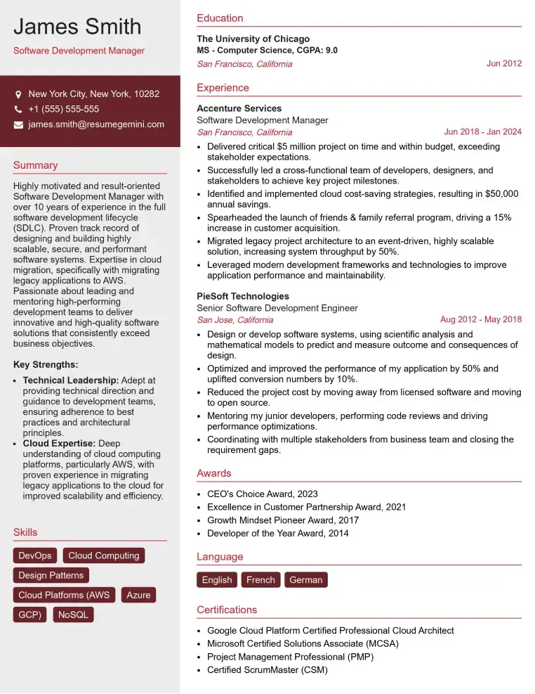
Check Out Resume Samples at ResumeGemini

Check Out Resume Samples at ResumeGemini
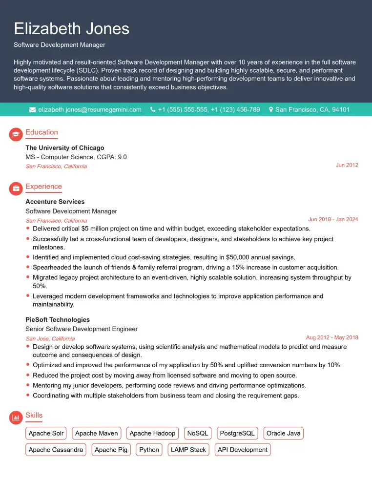
Check Out Resume Samples at ResumeGemini

Check Out Resume Samples at ResumeGemini

Check Out Resume Samples at ResumeGemini
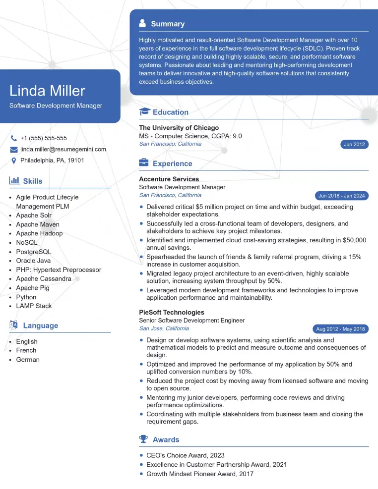
Check Out Resume Samples at ResumeGemini

Check Out Resume Samples at ResumeGemini
Explore more articles
Users Rating of Our Blogs
Share Your Experience
We value your feedback! Please rate our content and share your thoughts (optional).
What Readers Say About Our Blog
To the interviewgemini.com Webmaster.
Very helpful and content specific questions to help prepare me for my interview!
Thank you
To the interviewgemini.com Webmaster.
This was kind of a unique content I found around the specialized skills. Very helpful questions and good detailed answers.
Very Helpful blog, thank you Interviewgemini team.