Interviews are more than just a Q&A session—they’re a chance to prove your worth. This blog dives into essential Circuit Testing and Troubleshooting interview questions and expert tips to help you align your answers with what hiring managers are looking for. Start preparing to shine!
Questions Asked in Circuit Testing and Troubleshooting Interview
Q 1. Explain the difference between static and dynamic circuit testing.
Static and dynamic testing are two fundamental approaches to circuit verification. Static testing involves analyzing a circuit’s design without actually powering it up. This includes visually inspecting the circuit board for any obvious defects, checking the schematic for design errors, and verifying component values against the bill of materials. Think of it like reviewing blueprints before construction begins – you catch potential problems before they cause major issues. Dynamic testing, conversely, involves applying power and signals to the circuit and observing its behavior. This allows us to assess the circuit’s functionality under operational conditions, verifying its response to various inputs and ensuring its outputs meet specifications. This is like actually testing the building’s functionality, making sure plumbing, electricity and other systems work correctly.
For example, static testing might reveal a missing resistor identified during a visual inspection. Dynamic testing might reveal an unexpected delay in signal propagation, indicating a potential problem with component timing or circuit layout.
Q 2. Describe your experience with different types of circuit test equipment (e.g., oscilloscopes, multimeters, logic analyzers).
My experience encompasses a wide range of test equipment. Multimeters are indispensable for basic measurements like voltage, current, and resistance. I frequently use them for initial checks to isolate faulty components. Oscilloscopes are critical for analyzing dynamic signals, allowing me to visualize waveforms, measure frequency, and identify signal integrity issues like noise or distortion. I’ve used them extensively to debug timing problems in high-speed digital circuits. Logic analyzers are particularly useful for analyzing digital signals, capturing and displaying the state of multiple digital lines simultaneously. They help identify timing violations, data errors, and other glitches in digital systems. For instance, I once used a logic analyzer to pinpoint a race condition in a microcontroller program that was causing intermittent system crashes. In one project involving a complex FPGA design, the oscilloscope and logic analyzer worked in tandem to track down a subtle timing issue causing data corruption.
Q 3. How do you troubleshoot a circuit with intermittent faults?
Troubleshooting intermittent faults is challenging, requiring a systematic approach. My strategy starts with careful observation. I try to reproduce the fault by manipulating factors like temperature, vibration, or power supply. This helps identify potential triggers. Once a trigger is suspected, I use various instruments to monitor the circuit’s behavior. I might employ an oscilloscope to capture the signal before, during, and after the fault, looking for subtle changes or anomalies. I also use thermal imaging to identify components experiencing unexpected heating, which is a common indicator of an intermittent problem. For example, I once tracked down an intermittent short circuit in a power supply by carefully observing the circuit’s behavior under varying load conditions and using a thermal imager to pinpoint the faulty solder joint.
Furthermore, I might use specialized equipment like a current probe to meticulously monitor current fluctuations. This approach is essential when subtle variations in current draw are the only indicators of the intermittent issue. Documentation is key – keeping a detailed record of observations and test results helps avoid overlooking crucial details.
Q 4. What are some common causes of circuit malfunctions?
Circuit malfunctions stem from various sources. Component failure is a common culprit; resistors might drift out of tolerance, capacitors might fail open or short, and integrated circuits could be damaged by static electricity or overvoltage. Poor soldering, leading to cold solder joints or shorts, is another frequent issue. Design flaws, such as incorrect component values or inadequate signal routing, can also cause malfunctions. Environmental factors, such as temperature extremes, humidity, and vibration, can contribute to component degradation and ultimately failures. Finally, electromagnetic interference (EMI) can disrupt sensitive circuits, leading to unpredictable behavior. For example, a recent project involved a system failing due to a poorly shielded power supply that was inducing noise into a sensitive analog signal path.
Q 5. Explain your process for debugging a faulty circuit board.
My debugging process for faulty circuit boards follows a structured approach. I begin with a thorough visual inspection, checking for any obvious physical damage like cracked components or burnt traces. Then, I carefully review the circuit schematic and related documentation to understand the circuit’s functionality. Next, I perform basic electrical measurements using a multimeter to check voltages, currents, and resistances at key points, comparing them to the expected values. This often helps isolate the faulty section of the board. If the problem isn’t immediately apparent, I use more sophisticated instruments such as oscilloscopes and logic analyzers to analyze signals and pinpoint the precise location of the malfunction.
Throughout this process, I meticulously document all findings, including measurements, observations, and troubleshooting steps. This methodical approach helps identify the root cause and prevents the problem from recurring. A recent example involved a board with intermittent data loss. By carefully tracing the data path using a logic analyzer, I identified a poorly routed signal line that was susceptible to noise pickup, causing the data corruption. Reshielding the trace solved the problem completely.
Q 6. Describe your experience with automated test equipment (ATE).
I have extensive experience with automated test equipment (ATE), specifically in production environments. ATE systems significantly streamline the testing process, allowing for high-throughput testing and consistent quality control. I’m proficient in programming and operating various ATE platforms, designing test programs based on circuit specifications, and interpreting the test results to identify defective units. ATE systems often incorporate various measurement instruments like multimeters, oscilloscopes, and function generators, all controlled by a central computer. This automation significantly reduces human error and allows for rapid testing of large batches of circuit boards. For instance, in my previous role, I was involved in developing and implementing an ATE system for testing high-volume production of power supply units, dramatically improving testing efficiency and ensuring consistent quality.
Q 7. How do you interpret circuit schematics and datasheets?
Interpreting schematics and datasheets is crucial for circuit analysis and troubleshooting. I start by carefully examining the schematic to understand the circuit’s overall architecture, identifying major components and their interconnections. The schematic provides a visual representation of the circuit’s topology, allowing me to trace signal paths and identify potential problem areas. Datasheets provide detailed specifications for individual components, including their electrical characteristics, operating parameters, and package dimensions. They are essential for verifying component values, ensuring proper operation within specified limits, and understanding potential limitations.
For example, I might use the datasheet to find the maximum current rating of a specific resistor and compare it with the actual current flowing through the circuit. I also refer to datasheets to understand the timing characteristics of integrated circuits, which helps in diagnosing timing-related problems. I use both schematics and datasheets to verify signal integrity, ensure proper voltage levels, and check for potential impedance mismatches.
Q 8. What are your preferred methods for documenting test results?
My preferred method for documenting test results prioritizes clarity, traceability, and ease of analysis. I utilize a combination of techniques to ensure comprehensive and reliable records. For simple tests, a well-formatted spreadsheet (e.g., Excel or Google Sheets) is sufficient, with columns for test parameters, expected results, actual results, pass/fail status, and any relevant notes. For more complex projects, I leverage a dedicated test management system (like Jira or TestRail) to track test cases, execution status, defects, and overall project progress. This system provides version control, reporting capabilities, and collaborative features. Regardless of the tool, I always ensure the documentation is clear, concise, and readily accessible to all stakeholders. A key element is including screenshots or videos for visual confirmation of results, especially for complex circuits with multiple interactive components. This ensures repeatability and makes the results easy to understand and verify.
Q 9. How familiar are you with different testing methodologies (e.g., black box, white box)?
I’m very familiar with both black-box and white-box testing methodologies. Black-box testing focuses on the functionality of the circuit without regard to its internal workings. It’s like testing a car’s acceleration without knowing how the engine operates. This approach relies on inputting various signals and observing the output, allowing for a holistic evaluation. White-box testing, on the other hand, involves understanding the circuit’s internal structure and design. It’s like disassembling the car’s engine to inspect the individual parts and their interactions. This allows for thorough testing of specific components and paths, often crucial for identifying subtle design flaws. I often use a combination of both – black-box to ensure overall functionality, and white-box to pinpoint specific areas needing attention or optimization. For example, a black-box test might check the output voltage, while a white-box test could measure the voltage at intermediate points within the circuit to track signal integrity along specific paths.
Q 10. Explain your experience with different types of testing (e.g., functional, performance, stress).
My experience encompasses functional, performance, and stress testing. Functional testing verifies that the circuit meets its design specifications and performs its intended functions. This includes testing various operational modes and scenarios. For instance, verifying the correct output voltage, frequency response, and signal integrity under normal operating conditions. Performance testing focuses on the circuit’s speed and efficiency under various loads. This helps optimize resource utilization and identify bottlenecks. For example, measuring the power consumption of a circuit at different operating loads. Stress testing pushes the circuit beyond its normal operating limits to evaluate its robustness and reliability. It helps identify failure points and margins of safety. This includes tests like high-temperature operations, over-voltage conditions, or extreme frequencies. A practical example was testing a power supply’s performance under extreme temperature variations and over-current conditions. We identified a critical component failure point, leading to design improvements for enhanced stability and reliability.
Q 11. How do you prioritize multiple testing tasks?
Prioritizing multiple testing tasks requires a structured approach. I typically use a risk-based prioritization matrix, considering factors like: criticality (how essential is the functionality to the overall system), risk (probability and impact of failure), and urgency (deadlines and dependencies). High-risk, critical functionalities are prioritized first. For example, if testing a life-critical medical device, safety-related functionalities will have the highest priority. I also employ a dependency analysis to identify tasks that need to be completed before others can start. Using a project management tool like Jira or MS Project helps visualize the workflow, dependencies, and progress. This ensures efficient resource allocation and timely completion of testing within budget and deadlines.
Q 12. Describe a time you had to troubleshoot a complex circuit problem. What was the solution?
In one project, a complex signal processing circuit showed intermittent signal loss. Initial black-box testing revealed the problem but not the cause. Using a white-box approach, I systematically measured signals at various points along the circuit’s path using an oscilloscope. I discovered a high-frequency oscillation on one of the internal signal lines that was exceeding the operational limits of a critical amplifier. The oscillation was subtle and only appeared under specific operating conditions. I analyzed the circuit layout, identifying a poor grounding scheme as the root cause of the oscillation. The solution involved rerouting the ground planes and adding decoupling capacitors to mitigate the ground bounce. This resolved the signal loss, improving the reliability and stability of the circuit.
Q 13. How familiar are you with signal integrity and impedance matching?
I possess a strong understanding of signal integrity and impedance matching. Signal integrity refers to maintaining the quality of a signal as it travels through a circuit. Factors like reflections, crosstalk, and noise can degrade signal integrity. Impedance matching is critical to minimizing signal reflections at interfaces between different circuit components. Mismatches can lead to signal loss and distortion. I utilize tools like simulation software (e.g., SPICE) to analyze and predict signal integrity issues, and employ techniques such as careful trace routing, controlled impedance structures (e.g., microstrips), and termination resistors to ensure optimal performance. A practical example is working with high-speed digital signals where impedance mismatches can lead to signal distortion and data errors. Through proper impedance matching, we ensured reliable data transmission.
Q 14. Explain your experience with PCB design and layout review for testability.
My experience includes reviewing PCB designs to ensure testability. This involves reviewing the layout for accessibility of test points, consideration of signal routing for ease of probing, and minimizing potential interference. Proper placement of test points is essential for easy access during functional and diagnostic testing. Design for Test (DFT) techniques, such as built-in self-test (BIST) structures, can be incorporated during the design phase to improve testability and reduce the overall testing time. I’ve used tools like Altium Designer and Eagle to review PCB layouts and ensure sufficient clearance around components for probe access. A crucial element is to identify potential sources of noise and interference and implement strategies to mitigate them during the design stage. This preventative approach greatly simplifies the troubleshooting process and reduces the risk of errors during circuit testing.
Q 15. How do you identify and isolate noise in a circuit?
Identifying and isolating noise in a circuit is crucial for accurate testing and reliable operation. Noise, unwanted electrical signals, can manifest in various ways, masking the true circuit behavior. My approach involves a systematic process:
Observation and Measurement: I start by carefully observing the circuit’s behavior, noting any unusual fluctuations or erratic signals. I use oscilloscopes, spectrum analyzers, and multimeters to precisely measure voltages, currents, and frequencies at various points in the circuit. This helps pinpoint the location and characteristics of the noise.
Signal Filtering: Once the noise’s frequency range is identified, I employ appropriate filtering techniques. For example, if the noise is high-frequency, a low-pass filter can effectively attenuate it. Conversely, a high-pass filter can remove low-frequency noise. The choice of filter depends on the specific noise characteristics and the desired signal preservation.
Shielding and Grounding: Poor grounding and inadequate shielding can be major contributors to noise. I meticulously check the circuit’s grounding scheme, ensuring a single, low-impedance ground path. I also consider adding shielding to sensitive components or wires to isolate them from external electromagnetic interference (EMI).
Source Identification: Through careful analysis of the waveforms and measurements, I trace the noise source. This could involve identifying faulty components, poorly designed layouts, or external interference sources like nearby motors or power supplies.
Isolation Techniques: Once the noise source is identified, I isolate it. This might involve physically separating the noisy component, using opto-isolators to decouple noisy signals, or implementing differential signaling to cancel out common-mode noise.
For instance, I once worked on a project where a high-frequency switching power supply was injecting noise into a sensitive analog signal path. By implementing a combination of shielding, a ferrite bead filter, and careful grounding, we effectively eliminated the noise and improved the system’s performance.
Career Expert Tips:
- Ace those interviews! Prepare effectively by reviewing the Top 50 Most Common Interview Questions on ResumeGemini.
- Navigate your job search with confidence! Explore a wide range of Career Tips on ResumeGemini. Learn about common challenges and recommendations to overcome them.
- Craft the perfect resume! Master the Art of Resume Writing with ResumeGemini’s guide. Showcase your unique qualifications and achievements effectively.
- Don’t miss out on holiday savings! Build your dream resume with ResumeGemini’s ATS optimized templates.
Q 16. Describe your experience with fault injection techniques.
Fault injection is a powerful technique for testing a circuit’s robustness and identifying potential vulnerabilities. My experience encompasses both hardware and software-based methods. Hardware methods include injecting voltage spikes, current surges, and varying the supply voltage to assess the circuit’s response to unexpected events. Software techniques, typically used in embedded systems, involve injecting erroneous data or manipulating software variables to simulate faults.
In one project, we used a dedicated fault injection system to simulate single-event upsets (SEUs) in a space-qualified microprocessor. By injecting controlled bit flips into the microprocessor’s memory, we verified the effectiveness of its error correction mechanism and ensured its resilience in harsh space environments.
I’m also familiar with various fault injection methodologies, including:
- Random Fault Injection: Injecting faults randomly to assess overall system robustness.
- Targeted Fault Injection: Focusing on specific components or functionalities to pinpoint vulnerabilities.
- Stuck-at Fault Injection: Simulating a component being stuck at a particular logic level (high or low).
Careful planning and analysis are critical for effective fault injection. The injected faults must be carefully controlled and documented, ensuring reproducibility and accurate assessment of the system’s behavior.
Q 17. What are some common safety precautions you take when working with circuits?
Safety is paramount when working with circuits. My safety practices are meticulous and consistent. They include:
Proper Power Down: Always disconnecting the power supply before working on any circuit. I use a power strip with a visible on/off switch for easy control and visibility.
Safety Equipment: Using appropriate personal protective equipment (PPE) such as safety glasses, gloves, and anti-static wrist straps to prevent accidental injury or static discharge damage.
Insulated Tools: Employing insulated tools to prevent electrical shocks. This includes insulated screwdrivers, pliers, and probes.
Double Checking: Thoroughly checking and double-checking connections before applying power. I often use a multimeter to verify voltage levels and continuity before proceeding.
Appropriate Workspace: Maintaining a clean, organized, and well-lit workspace to prevent accidents and ensure focus.
Emergency Procedures: Being familiar with the location of fire extinguishers and emergency exits and understanding the appropriate emergency procedures.
A memorable incident involved a colleague who accidentally touched a high-voltage capacitor. This reinforced the importance of meticulous safety procedures, particularly proper power-down and the use of insulated tools. We reviewed our safety protocols and implemented further training to prevent similar incidents.
Q 18. How do you handle unexpected test results?
Unexpected test results are opportunities for learning and refinement. My approach is systematic and involves several steps:
Verification: First, I meticulously verify the test setup and procedure to ensure there were no errors in the test configuration. I re-check connections, instrument settings, and test parameters.
Data Analysis: I carefully analyze the unexpected results, comparing them to expected behavior and looking for patterns or anomalies.
Troubleshooting: If the error isn’t immediately apparent, I start troubleshooting using systematic methods. This may involve isolating sections of the circuit, using diagnostic tools, and gradually narrowing down the potential problem areas.
Documentation: I thoroughly document the unexpected results, including all observations, measurements, and troubleshooting steps. This documentation is valuable for future analysis and debugging.
Root Cause Analysis: I strive to identify the root cause of the unexpected results. This could involve examining component specifications, schematics, and design documents.
Corrective Actions: I implement necessary corrective actions to address the identified issue, whether it involves replacing faulty components, modifying the design, or improving the testing methodology.
For instance, I once encountered unexpected voltage readings in a power amplifier. Through careful investigation, I discovered a faulty resistor that had drifted significantly from its nominal value. Replacing the resistor resolved the issue.
Q 19. What is your experience with using simulation tools (e.g., SPICE)?
I have extensive experience using SPICE simulation tools, primarily LTSpice, for circuit analysis and design. SPICE allows for the accurate modeling and simulation of various circuit behaviors before physical prototyping, significantly reducing development time and costs. I am proficient in creating circuit schematics, defining component parameters, and running simulations to analyze voltage, current, and frequency responses. I frequently use transient, AC, and DC analysis to thoroughly evaluate circuit performance under different operating conditions.
In a recent project, we used LTSpice to model a complex switched-mode power supply. By simulating various load conditions and input voltage variations, we optimized the design for efficiency and stability before committing to the final hardware implementation. This avoided costly iterations during the physical prototyping phase.
My skills extend beyond basic simulation to include:
- Monte Carlo analysis: Evaluating the impact of component tolerances on circuit performance.
- Temperature analysis: Assessing the effects of temperature variations on circuit behavior.
- Sensitivity analysis: Determining the sensitivity of the circuit to changes in component values.
Q 20. Explain your understanding of circuit analysis techniques (e.g., nodal analysis, mesh analysis).
Circuit analysis techniques are fundamental to understanding circuit behavior. Nodal analysis and mesh analysis are two powerful methods for solving circuit equations.
Nodal analysis focuses on the voltage at each node (junction) in a circuit. By applying Kirchhoff’s current law (KCL) at each node, a set of equations is derived that can be solved for the node voltages. This method is particularly efficient for circuits with many voltage sources. For example, consider a simple circuit with three nodes. Applying KCL at each node, we can obtain three equations that can be solved for the node voltages.
Mesh analysis focuses on the currents flowing in each mesh (loop) of a circuit. By applying Kirchhoff’s voltage law (KVL) to each mesh, a set of equations is derived that can be solved for the mesh currents. Mesh analysis is particularly effective for circuits with many current sources. For instance, a circuit with two meshes would yield two equations based on KVL, solvable for the mesh currents.
Beyond these fundamental methods, I’m also familiar with other techniques such as superposition, Thevenin’s theorem, and Norton’s theorem, which provide alternative approaches for simplifying and analyzing complex circuits.
The choice of method depends on the specific circuit topology and the desired information. Sometimes, a combination of techniques is the most efficient approach for complex circuits.
Q 21. How do you ensure the accuracy and reliability of your test results?
Ensuring the accuracy and reliability of test results is crucial for producing reliable products. My approach is multifaceted:
Calibration: Regular calibration of all test equipment, including oscilloscopes, multimeters, and signal generators, is essential. Calibration ensures that the instruments provide accurate measurements within their specified tolerances.
Traceability: Maintaining detailed documentation of all test procedures, measurements, and results. This includes documenting the test equipment used, its calibration status, and any deviations from the standard test procedures.
Statistical Analysis: Using statistical methods to evaluate the consistency and repeatability of test results. This helps to identify potential sources of error and ensures that the results are statistically significant.
Blind Testing: In some cases, conducting blind testing where the tester is unaware of the expected results can help to eliminate bias and ensure objectivity.
Peer Review: Having other engineers review the test procedures and results can help identify potential errors and ensure accuracy.
Redundancy and Cross-Checking: Employing multiple test methods or using redundant components in the circuit to confirm the accuracy of the results.
For example, when testing a high-precision analog-to-digital converter (ADC), we used multiple ADCs for cross-checking, and performed multiple test runs to ensure statistical significance of the results, along with detailed documentation of each step of the test.
Q 22. Describe your experience with using test automation frameworks.
My experience with test automation frameworks is extensive. I’ve worked extensively with frameworks like pytest (Python) and TestStand (National Instruments), and have also developed custom frameworks tailored to specific project needs. A key aspect of my approach is selecting the right framework for the job. For instance, pytest’s flexibility and extensibility are ideal for complex embedded systems testing, while TestStand’s structured approach excels in large-scale production testing environments. I’m proficient in designing and implementing automated tests, including unit tests, integration tests, and system tests, leveraging these frameworks’ capabilities for data-driven testing, parallel execution, and reporting. In one project, using pytest and a custom fixture, we reduced our test execution time by over 70% by parallelizing tests across multiple hardware targets.
A successful automation strategy isn’t just about using a framework; it involves careful test case design, effective code management, and robust reporting. I prioritize creating maintainable and reusable test code to ensure long-term value and minimize future maintenance efforts. I have practical experience in integrating automated tests into CI/CD pipelines, ensuring that quality checks are seamlessly incorporated into the development workflow.
Q 23. How familiar are you with different programming languages used in circuit testing (e.g., Python, LabVIEW)?
My programming language proficiency directly supports my circuit testing expertise. I’m highly proficient in Python, using it for everything from test scripting and data analysis to creating custom test harnesses. Python’s versatility and extensive libraries (like NumPy and SciPy) are invaluable for signal processing and data manipulation tasks frequently encountered in circuit testing. I’m also experienced with LabVIEW, particularly beneficial for its graphical programming environment and strong integration with National Instruments hardware. LabVIEW’s strengths lie in real-time data acquisition and instrument control, making it ideal for automating complex test setups involving numerous instruments. I’ve successfully used LabVIEW to develop automated test benches for high-speed digital circuits, accurately capturing and analyzing waveforms at frequencies exceeding 1 GHz. I also possess working knowledge of C and C++, especially for lower-level interactions with embedded systems and hardware drivers.
Q 24. What is your experience with designing and implementing test fixtures?
Designing and implementing effective test fixtures is crucial for reliable and repeatable testing. A test fixture, in essence, sets up the environment needed for a test to run. This includes configuring hardware, initializing instruments, and loading test data. My approach to designing test fixtures emphasizes modularity and reusability. I strive to create fixtures that are easily configurable and adaptable to different tests. For example, I might create a fixture that initializes a power supply and multimeter, setting specific voltage levels and current limits, and then reuse that fixture across many different tests involving different components under various voltage conditions.
I also prioritize robust error handling within fixtures, ensuring that failures are gracefully handled and reported, preventing unintended consequences. In a recent project, I developed a fixture that automatically detected and reported faulty connections, preventing erroneous test results and saving considerable debugging time. Proper fixture design significantly improves the overall efficiency and reliability of the testing process.
Q 25. Describe your experience with different types of sensors and transducers used in circuit testing.
My experience spans a wide range of sensors and transducers used in circuit testing. This includes various types of voltage and current probes, temperature sensors (thermocouples, RTDs, thermistors), pressure sensors, optical sensors (photodiodes, phototransistors), and accelerometers. I understand the characteristics of each sensor, including accuracy, precision, response time, and noise levels. This knowledge is critical for selecting the appropriate sensor for a given task and interpreting the acquired data. For instance, the choice between a thermocouple and an RTD depends on factors like temperature range, accuracy requirements, and cost. I also possess experience in interfacing these sensors with different data acquisition systems, ensuring accurate and reliable data acquisition. This often involves understanding signal conditioning techniques, such as amplification, filtering, and analog-to-digital conversion.
Further, I have experience calibrating sensors to ensure accuracy and mitigating the impact of systematic errors. Calibration techniques and the frequency with which it’s done depends entirely on the sensor’s specifications and how crucial precision is. A well-calibrated sensor is the cornerstone of reliable and reproducible test results.
Q 26. How do you write effective test plans and procedures?
Writing effective test plans and procedures is essential for a successful testing process. My approach starts with a clear understanding of the system under test (SUT) and its requirements. The test plan outlines the overall scope, objectives, resources, schedule, and risks involved in the testing process. I ensure it is detailed yet concise, readily understood by all team members. Key aspects included are the test strategy (e.g., black-box, white-box), selection of testing techniques, and identification of potential risks and mitigation strategies. The test plan also defines metrics for success, enabling objective assessment of the testing process.
Test procedures, on the other hand, provide detailed step-by-step instructions for executing individual tests. They are written to be clear, unambiguous, and easily followed. I use clear language, avoiding technical jargon where possible. Test procedures include setup instructions, test steps, expected results, and pass/fail criteria. In addition to this, I often include diagrams, flowcharts, or other visual aids to improve comprehension and reduce ambiguity. Well-written test plans and procedures contribute significantly to test efficiency, consistency, and overall project success.
Q 27. How do you manage your time and prioritize tasks effectively during a troubleshooting process?
Effective time management and task prioritization are crucial during troubleshooting. My approach involves a structured and systematic process. I begin by gathering all relevant information, including error messages, diagnostic logs, and circuit schematics. I then prioritize tasks based on their potential impact and urgency, using techniques like the Pareto principle (80/20 rule) to focus on the most likely causes first. For instance, I’d first investigate obvious issues like loose connections or power supply problems before delving into more complex circuit behavior. This systematic approach often allows for faster identification and resolution of the problem.
I use tools like spreadsheets or task management software to track my progress and ensure that no tasks are overlooked. Regularly reviewing my progress against the timeline helps me identify and address potential delays proactively. Effective communication with team members is also key, enabling collaboration and ensuring that tasks are assigned and completed efficiently. Ultimately, a structured approach ensures efficient troubleshooting while minimizing downtime.
Q 28. What are some common challenges you face in circuit testing and how do you overcome them?
Circuit testing presents several common challenges. One major challenge is dealing with intermittent faults, which can be difficult to reproduce and diagnose. My strategy involves meticulous documentation, thorough testing under varying conditions (temperature, voltage variations, etc.), and the use of advanced diagnostic tools such as logic analyzers and oscilloscopes to capture transient events. Another common challenge is noise and interference. Effective shielding, grounding techniques, and appropriate filtering are vital for obtaining accurate measurements. This includes employing differential probes to minimize noise pickup. Sometimes, dealing with complex circuit designs with many interconnected components can be challenging. A structured approach, employing modular testing and debugging strategies, greatly simplifies this process. This could include isolating sections of the circuit for individual testing.
Finally, access to specialized equipment and expertise can sometimes be a constraint. Collaboration with other engineers and leveraging resources across teams can help overcome such limitations. Continuous learning, staying updated on the latest testing techniques, and using advanced testing tools and equipment greatly enhances my ability to address the challenges and ensures high-quality results.
Key Topics to Learn for Circuit Testing and Troubleshooting Interview
- Basic Circuit Analysis: Understanding Ohm’s Law, Kirchhoff’s Laws, series and parallel circuits, voltage dividers, and current dividers. Practical application: Diagnosing simple circuit malfunctions based on voltage and current readings.
- Digital Logic and Troubleshooting: Familiarity with logic gates (AND, OR, NOT, XOR, etc.), Boolean algebra, and troubleshooting digital circuits using logic analyzers or oscilloscopes. Practical application: Identifying faulty components in a digital circuit by analyzing logic states.
- Signal Integrity and Troubleshooting: Understanding signal reflections, impedance matching, noise, and crosstalk. Practical application: Troubleshooting high-speed digital circuits for signal degradation issues.
- Testing Equipment and Instrumentation: Proficiency with multimeters, oscilloscopes, logic analyzers, signal generators, and function generators. Practical application: Selecting and using appropriate test equipment to diagnose specific circuit problems.
- Soldering and Desoldering Techniques: Proper techniques for safely and effectively soldering and desoldering components on PCBs. Practical application: Repairing damaged circuits by replacing faulty components.
- Schematic Reading and Interpretation: Ability to understand and interpret circuit schematics, including component values, connections, and signal flow. Practical application: Tracing signals and identifying potential failure points within a circuit.
- Troubleshooting Methodologies: Systematic approaches to fault finding, including the use of half-splitting, signal tracing, and substitution techniques. Practical application: Efficiently isolating and resolving circuit malfunctions.
- Safety Procedures: Understanding and adhering to safe practices while working with electrical circuits and equipment. Practical application: Preventing accidents and ensuring personal safety during troubleshooting.
Next Steps
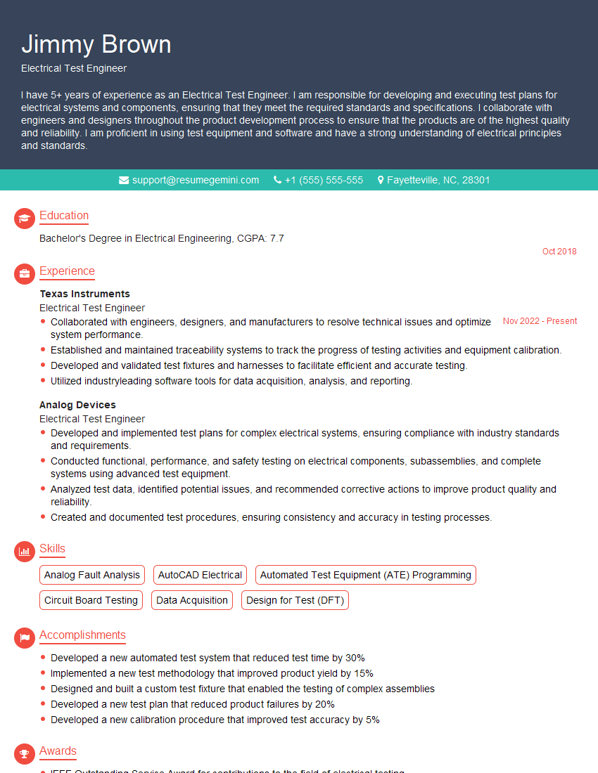
Mastering Circuit Testing and Troubleshooting is crucial for career advancement in electronics, engineering, and related fields. It demonstrates a strong foundation in electrical principles and hands-on problem-solving skills highly valued by employers. To significantly boost your job prospects, create a compelling and ATS-friendly resume that highlights your skills and experience effectively. ResumeGemini is a trusted resource that can help you build a professional resume tailored to your specific needs. We provide examples of resumes specifically designed for candidates in Circuit Testing and Troubleshooting to guide you through the process. Take the next step towards your dream career today!
Explore more articles
Users Rating of Our Blogs
Share Your Experience
We value your feedback! Please rate our content and share your thoughts (optional).
What Readers Say About Our Blog
To the interviewgemini.com Webmaster.
Very helpful and content specific questions to help prepare me for my interview!
Thank you
To the interviewgemini.com Webmaster.
This was kind of a unique content I found around the specialized skills. Very helpful questions and good detailed answers.
Very Helpful blog, thank you Interviewgemini team.