Feeling uncertain about what to expect in your upcoming interview? We’ve got you covered! This blog highlights the most important Electrical PLC Programming interview questions and provides actionable advice to help you stand out as the ideal candidate. Let’s pave the way for your success.
Questions Asked in Electrical PLC Programming Interview
Q 1. Explain the difference between a ladder diagram and a function block diagram.
Both Ladder Diagrams (LD) and Function Block Diagrams (FBD) are graphical programming languages for PLCs, but they differ significantly in their approach to representing logic. Think of LD as a wiring diagram, and FBD as a block diagram showing interconnected functions.
Ladder Diagrams (LD): LD uses a ladder-like structure with two vertical rails representing power supply and contacts (inputs) in series and parallel arrangements between them. Outputs are placed on the right side. It’s intuitive for electricians because it resembles electrical schematics. Each rung represents a Boolean logic statement; the rung is ‘true’ if the path is complete.
Example: A simple LD rung might have a normally open (NO) contact representing a push button connected to an output representing a motor. If the push button is pressed (input true), the motor turns on (output true).
Function Block Diagrams (FBD): FBD represents logic using interconnected functional blocks. Each block represents a specific function (like a timer, counter, or mathematical operation), with inputs and outputs clearly defined. This is more modular and hierarchical than LD, allowing for better organization and reusability of code, especially in complex projects.
Example: An FBD might show a 'Timer' block connected to a 'Comparator' block. The timer output is fed into the comparator to determine if a time limit has been exceeded.
In essence, LD is easier to learn for beginners due to its visual simplicity resembling relay logic, while FBD is better suited for larger and more complex automation systems requiring modularity and structured programming.
Q 2. Describe your experience with different PLC programming languages (e.g., ladder logic, structured text).
My experience encompasses a broad range of PLC programming languages. I’ve extensively used Ladder Logic (LD) for its intuitive visual representation, particularly in smaller projects and those involving electromechanical systems. I find it especially helpful for electricians and technicians accustomed to relay logic diagrams.
I’m also proficient in Structured Text (ST), a high-level language resembling Pascal or C. ST is invaluable for complex algorithms, mathematical calculations, and string manipulations, tasks where LD can become cumbersome. I’ve utilized ST in several large-scale projects to handle advanced control strategies and data manipulation.
Furthermore, I have working knowledge of Function Block Diagram (FBD) and Instruction List (IL), although my primary focus remains on LD and ST due to their efficiency and widespread industry adoption in the specific types of projects I’ve undertaken. I find the combination of LD for basic control and ST for complex logic offers the best balance of readability and power.
Q 3. How do you troubleshoot a PLC program that is malfunctioning?
Troubleshooting a malfunctioning PLC program requires a systematic approach. I begin by reviewing the program’s logic and documentation, if available. My initial steps often involve:
- Checking input/output signals: I use the PLC’s diagnostic tools to verify that inputs are correctly reflecting the real-world conditions and that outputs are responding as expected.
- Analyzing error logs and status bits: Many PLCs keep detailed logs of errors and status changes. These logs are invaluable in pinpointing the source of the problem.
- Using online monitoring: Observing the values of variables and internal signals in real time allows me to trace the flow of execution and identify where things go wrong.
- Step-by-step execution: If necessary, I can step through the program line by line to identify precisely where the unexpected behavior occurs.
- Simulation: Creating a simulated environment to reproduce the faulty behavior allows testing and debugging changes without affecting real-world equipment.
Once the problem is isolated, I make the necessary corrections, usually involving modifying the program logic, addressing faulty hardware, or adjusting configuration settings. Thorough testing and validation are crucial after any changes. For instance, I recently resolved an issue where a timer wasn’t resetting properly by identifying a misconfigured bit in the program logic.
Q 4. Explain the concept of timers and counters in PLC programming.
Timers and counters are essential elements in PLC programming used to control the timing and sequencing of operations. They are often crucial for implementing time-based actions.
Timers: Timers measure elapsed time. Common types include:
- ON-delay timer: The output turns ON after a set time delay has elapsed since the input turned ON.
- OFF-delay timer: The output remains ON for a set time delay after the input turns OFF.
- Retentive timer: Retains its accumulated time even if the input is interrupted.
Example: An ON-delay timer could be used to activate a conveyor belt a few seconds after a sensor detects a part.
Counters: Counters count events or pulses. Types include:
- Up-counters: Increment the counter value with each pulse.
- Down-counters: Decrement the counter value with each pulse.
- Up/down-counters: Can increment or decrement depending on the input signal.
Example: A counter could track the number of parts processed on a production line.
Both timers and counters are crucial in various applications, ranging from simple timing functions to sophisticated process control sequences.
Q 5. What are the different types of addressing modes used in PLCs?
PLCs utilize various addressing modes to access memory locations, each offering advantages in different situations. The most common include:
- Symbolic Addressing: Uses user-defined names (symbols) for variables, making the program more readable and maintainable. For example,
Motor_Speedis more descriptive than%MW10. - Absolute Addressing: Directly specifies the memory location using an address. This is less readable but can be faster for direct access. For example,
%MW10refers to a specific memory word. - Indirect Addressing: Uses the value stored in one memory location to point to another memory location. This is flexible and allows for dynamic memory access. For example,
%MW[Index]where the content of theIndexvariable determines the actual memory word accessed. - Data Table Addressing: Organizes data into structured tables, making it easier to manage large amounts of data. This is commonly used in systems with many input and output points.
Choosing the right addressing mode depends on factors such as code readability, program complexity, and performance requirements.
Q 6. How do you handle data logging and reporting in a PLC system?
Data logging and reporting in a PLC system is critical for monitoring, analysis, and troubleshooting. Methods vary depending on the PLC and application. Common approaches include:
- Internal PLC Logging: Many PLCs offer built-in capabilities to log data to internal memory, which can then be downloaded for analysis. The frequency of logging and the amount of data stored are often configurable.
- External Data Acquisition Systems (DAQ): Specialized DAQ systems can collect data from the PLC and store it on a computer or server for more comprehensive analysis and archival.
- Database Integration: PLCs can be integrated with databases (like SQL) for storing and retrieving logged data. This enables sophisticated data analysis and reporting using database tools.
- HMI Reporting: Advanced HMIs can generate real-time reports and historical trends based on the data logged within the PLC or an external system. This often includes graphical displays of process variables over time.
In my experience, I’ve implemented data logging solutions using various methods, optimizing the choice based on factors like data volume, required reporting features, and the existing IT infrastructure.
Q 7. Describe your experience with HMI (Human-Machine Interface) programming and integration.
I have considerable experience in HMI programming and integration. My work has involved designing, developing, and deploying HMIs for various industrial applications, from simple monitoring panels to complex SCADA systems.
I’m proficient in several HMI software packages, including [mention specific software packages used, e.g., Wonderware InTouch, Rockwell FactoryTalk View, Siemens WinCC]. My expertise includes designing user interfaces, configuring alarms and notifications, integrating with PLCs using various communication protocols (e.g., Ethernet/IP, Modbus TCP, Profibus), and creating custom visualization elements.
A recent project involved developing an HMI for a complex packaging system. The HMI provided real-time monitoring of all system parameters, enabled remote control of critical processes, and generated detailed production reports. This required careful consideration of user workflows, alarm management, and data visualization to ensure optimal operator efficiency and system monitoring.
Q 8. Explain your understanding of safety protocols in PLC programming (e.g., E-stop circuits).
Safety is paramount in PLC programming, and E-stop circuits are a cornerstone of this. An E-stop (Emergency Stop) is a safety mechanism designed to immediately halt a machine or process in hazardous situations. It’s crucial that the E-stop circuit is designed with redundancy and failsafe measures to ensure that it functions reliably even in the event of component failure.
Typically, an E-stop circuit uses normally closed (NC) contacts in series with the main power supply to the PLC and the controlled equipment. When the E-stop button is pressed, these contacts open, immediately cutting power to the system. This is often implemented using multiple E-stop buttons strategically placed throughout the machine, each with its own NC contact in the series circuit, to ensure a high degree of reliability. The PLC’s program should monitor the E-stop signal; even if the PLC is rebooted or its program altered, the E-stop should immediately halt the process without needing to run any code.
Beyond E-stops, other safety protocols include light curtains, proximity sensors, and interlocks. These are all hard-wired safety circuits, often separate from the main PLC program, that directly interrupt power or signal the PLC to enter a safe state if a hazard is detected. This ensures safety even if the PLC’s software experiences a fault.
In my experience, designing a robust safety system requires meticulous attention to detail. I’ve worked on projects where multiple levels of safety were implemented, including hardware safety PLCs and emergency power-off switches, to guarantee worker safety in potentially hazardous manufacturing environments.
Q 9. How do you implement different control strategies (e.g., PID control, sequential control)?
PLCs are incredibly versatile and can implement various control strategies. Sequential control is the simplest, essentially executing a series of instructions in a predetermined order, often using timers and counters. Think of a simple automated assembly line: step 1, pick up part A; step 2, place part A; step 3, pick up part B; and so on. This can be implemented using ladder logic with timers to ensure proper sequencing.
//Example Ladder Logic Snippet (Illustrative) //Timer T1 times step 1 //Timer T2 times step 2 //Outputs OUT1, OUT2 control actuators
PID (Proportional-Integral-Derivative) control is far more sophisticated and is used for precise process control. It continuously adjusts an output to maintain a desired setpoint by considering the error (difference between the setpoint and the actual value), the integral of the error (accumulated error over time), and the derivative of the error (rate of change of the error). Imagine controlling the temperature of a furnace: a PID controller constantly adjusts the fuel input to keep the temperature at the desired level, compensating for changes in heat loss or other disturbances.
In my work, I’ve used both sequential and PID control extensively, often in combination. For example, a complex manufacturing process might use sequential control to move parts through different stages and PID control to regulate temperature or pressure at each step.
Q 10. Explain your experience with networking protocols in industrial automation (e.g., Ethernet/IP, Modbus).
Networking is essential in modern industrial automation. I have extensive experience with Ethernet/IP and Modbus, two widely used protocols. Ethernet/IP, a proprietary protocol developed by Rockwell Automation, offers high speed and robust communication, especially well-suited for larger, complex systems with high data throughput requirements. Modbus, an open standard, is simpler and widely supported across various vendors, making it ideal for systems requiring interoperability between different devices from diverse manufacturers.
Imagine a large-scale manufacturing facility. We might use Ethernet/IP to connect multiple PLCs and high-speed data acquisition devices in a high-bandwidth network. Simultaneously, we might utilize Modbus to communicate with simpler devices like temperature sensors or flow meters that don’t demand the same speed and bandwidth.
My experience involves configuring these protocols, troubleshooting network issues, and optimizing communication for maximum efficiency. I’m proficient in using network diagnostic tools and have resolved numerous connectivity problems in various industrial settings. This includes working with both TCP/IP and UDP communication methods in these protocols.
Q 11. How do you perform backups and restores of PLC programs?
Backing up and restoring PLC programs is critical for maintaining system stability and preventing costly downtime. The process typically involves several steps, starting with regularly scheduled backups. These backups should be stored securely, preferably in multiple locations, to protect against data loss due to hardware failure or other unforeseen events.
The method for creating backups depends on the specific PLC and its programming software. Many PLCs allow for direct export of the program files. This process often creates a backup file containing all the ladder logic, data tables, and other configuration settings. Some PLC platforms include features for version control and revision history. This enables comparing different versions of programs and retrieving older versions.
Restoring a backup is typically the reverse of the backup process. The restored program will overwrite the existing program, therefore, it’s essential to take note of the timestamp of the backup. I always create and test backups off-line before restoring them to avoid potential errors and system instability. In my experience, meticulous documentation of the backup schedule and procedure is paramount.
Q 12. Describe your experience with various input/output modules (e.g., analog, digital, communication modules).
Input/output (I/O) modules are the interface between the PLC and the real-world equipment. I have hands-on experience with various types, including digital, analog, and communication modules. Digital I/O modules handle on/off signals, like switches, sensors, and relays. Analog I/O modules handle continuous signals, such as temperature, pressure, and flow measurements from transducers. Communication modules connect the PLC to external networks or other devices via protocols such as Modbus or Ethernet/IP.
For instance, in a water treatment plant, we’d utilize analog I/O modules to read level sensors in water tanks, providing continuous feedback to the PLC. Digital I/O modules would control valves and pumps, switching them on and off based on the PLC’s logic. And, communication modules would allow the PLC to communicate with a supervisory control and data acquisition (SCADA) system for remote monitoring and control.
Choosing the correct I/O module is vital for successful project implementation. Factors to consider include signal type (digital, analog, frequency), voltage levels, and communication protocols. Incorrect selection can lead to inaccurate measurements, malfunctions, and even equipment damage.
Q 13. Explain the concept of interrupts in PLC programming.
Interrupts in PLC programming are mechanisms that allow the PLC to respond to events in real-time, outside the normal sequential execution of the program. Think of it like an urgent phone call interrupting your regular workday. When an interrupt occurs (for example, a high-priority sensor signal), the PLC immediately suspends its current task and executes a specific interrupt service routine (ISR) designed to handle that event.
For example, an emergency stop button signal can trigger an interrupt, causing the PLC to immediately shut down all outputs, regardless of the program’s current execution state. This ensures a rapid response to safety-critical events. Another example could be a high-speed counter input; the PLC can be set to respond immediately when the counter reaches a set value, triggering an immediate response in the process. This is different from polling, where the PLC continuously checks the sensor or counter’s status.
Interrupt handling is critical in situations where immediate responsiveness is vital. Careful design is required to avoid conflicts between different interrupt routines and ensure real-time response to priority events.
Q 14. How do you deal with data integrity and redundancy in a PLC system?
Data integrity and redundancy are crucial for reliable PLC operation. Data integrity refers to ensuring the accuracy and consistency of data within the PLC system. Redundancy involves having backup systems or components to ensure continued operation even if a primary system fails. These two concepts work together to guarantee the safety and reliability of the industrial process.
To ensure data integrity, we employ various techniques like cyclic redundancy checks (CRCs) to detect errors in data transmission, data validation checks within the PLC program, and careful consideration of data types and ranges to prevent overflow errors. Redundancy is often achieved through hardware redundancy (e.g., dual PLCs running in parallel, with one acting as a backup) or software redundancy (e.g., using data mirroring or checksums to detect and correct corrupted data). A combination of techniques is best to ensure that the complete system remains resilient.
In a critical application, like a nuclear power plant or an oil refinery, where even a short period of downtime could have serious consequences, we would implement multiple layers of redundancy and data integrity checks to ensure operational continuity and prevent hazardous situations. In my career, I have designed and implemented such critical systems with high-levels of safety and reliability.
Q 15. What is your experience with different PLC manufacturers (e.g., Allen-Bradley, Siemens)?
My experience spans several leading PLC manufacturers, primarily Allen-Bradley (Rockwell Automation) and Siemens. With Allen-Bradley, I’ve extensively used RSLogix 5000 and Studio 5000, working on projects ranging from simple machine control to complex automation systems. My proficiency includes ladder logic programming, function block diagrams (FBD), structured text (ST), and sequential function charts (SFC). With Siemens, I’m proficient in TIA Portal, utilizing ladder logic, FBD, and SCL (Structured Control Language) for various industrial applications. I’ve worked on projects involving both S7-1200 and S7-1500 PLCs. The key difference in my approach lies in understanding the specific strengths of each platform – for instance, Allen-Bradley’s strong structured programming capabilities versus Siemens’ powerful data handling and communication features. This understanding allows me to choose the right tools for the job and optimize the development process.
For example, in one project using Allen-Bradley, I leveraged the advanced features of Studio 5000 to develop a highly modular and reusable codebase, making maintenance and updates significantly easier. In another project with Siemens, I utilized the robust communication capabilities of the S7-1500 PLC to seamlessly integrate with a variety of third-party devices across a large-scale manufacturing plant.
Career Expert Tips:
- Ace those interviews! Prepare effectively by reviewing the Top 50 Most Common Interview Questions on ResumeGemini.
- Navigate your job search with confidence! Explore a wide range of Career Tips on ResumeGemini. Learn about common challenges and recommendations to overcome them.
- Craft the perfect resume! Master the Art of Resume Writing with ResumeGemini’s guide. Showcase your unique qualifications and achievements effectively.
- Don’t miss out on holiday savings! Build your dream resume with ResumeGemini’s ATS optimized templates.
Q 16. How do you handle different types of sensors and actuators in your PLC programs?
Handling diverse sensors and actuators is fundamental to PLC programming. The process involves understanding the sensor/actuator’s communication protocol (e.g., analog, digital, Profibus, Profinet), voltage levels, and signal types. I begin by carefully reviewing the device specifications to ensure correct integration. This includes selecting the appropriate input/output (I/O) modules for the PLC based on signal type and voltage. Digital sensors (switches, limit switches) are typically connected to discrete I/O, while analog sensors (temperature, pressure) require analog I/O modules for processing. Actuator control depends on the type of actuator and its power requirements (e.g., relay outputs for solenoids, PWM for motor speed control). Error handling is crucial; I often implement checks to verify sensor readings and respond accordingly to prevent system malfunction.
For instance, if integrating an analog temperature sensor, I would configure the PLC’s analog input module to appropriately scale the sensor’s raw voltage reading into meaningful temperature units. I’d then use this temperature value in the PLC program to activate a cooling system if the temperature surpasses a preset threshold. Similarly, controlling a pneumatic actuator may involve using a digital output to energize a solenoid valve, accompanied by safety interlocks to prevent accidental activation.
//Example code snippet (Illustrative - Syntax varies per PLC) IF Temperature > Threshold THEN Activate Cooling System; END_IF;Q 17. Describe your experience with PLC simulation software.
PLC simulation software is an invaluable tool for testing and debugging PLC programs without needing physical hardware. This significantly reduces development time and avoids potential damage to expensive equipment. I’m experienced with several simulation environments, including Rockwell Automation’s FactoryTalk Simulation and Siemens’ PLCSIM. These tools allow me to create virtual representations of the entire system, including PLCs, I/O modules, sensors, and actuators. I can then upload and test the PLC program in this virtual environment, observing its behavior and identifying any errors or inconsistencies before deployment to the actual hardware. This allows for thorough testing of various scenarios and edge cases. The use of simulation software is essential for ensuring a robust and reliable automation system.
In one project, using FactoryTalk Simulation, I was able to identify a critical timing issue in our control logic that would have caused production stoppages in the actual system. By simulating the entire process, we caught and rectified the error before deployment, saving valuable time and avoiding costly downtime.
Q 18. Explain the concept of self-documenting code in PLC programming.
Self-documenting code in PLC programming is the practice of writing code that is easily understandable and requires minimal external documentation. This improves maintainability and reduces errors. It’s achieved through clear variable naming, using comments extensively, and structuring the code logically. Meaningful variable names (e.g., `Motor_Speed`, `Temperature_Sensor`) are far more informative than cryptic abbreviations. Comments explain complex logic sections and the purpose of specific code blocks. Well-structured code, using functions and subroutines to break down large tasks into smaller, manageable units, greatly enhances readability. This approach makes it much easier for others (or even my future self) to understand and modify the code, reducing the risk of introducing errors during maintenance or upgrades.
Think of it like writing a well-organized essay versus a jumbled paragraph – the former is much easier to understand and follow. Similarly, well-documented PLC code helps ensure that everyone working on the project (present and future) can understand and maintain the system efficiently.
Q 19. How do you manage version control of PLC programs?
Version control is crucial for managing PLC programs, especially in collaborative projects or when dealing with frequent modifications. While dedicated version control systems like Git are not directly applied to the PLC program files themselves (due to their proprietary formats), I utilize version control for all supporting documentation, configuration files, and scripts. This includes using Git repositories to track changes in code comments, system diagrams, and configuration files associated with the PLC program. The PLC program itself is regularly backed up and versioned, typically using the PLC manufacturer’s software tools. This systematic approach allows easy rollback to previous versions if needed and provides a complete audit trail of all changes made to the system.
This method ensures that we can always revert to a stable version if a recent update introduces bugs. It also provides a complete history of the system’s evolution, proving invaluable during troubleshooting or when understanding past modifications.
Q 20. Describe your experience with SCADA systems and their integration with PLCs.
My experience with SCADA systems (Supervisory Control and Data Acquisition) is extensive, focusing primarily on their integration with PLCs. SCADA systems provide a user-friendly interface for monitoring and controlling industrial processes. They gather data from PLCs, present it visually (through HMIs or dashboards), and allow operators to adjust system parameters. The integration process often involves configuring communication protocols (e.g., Modbus TCP, Ethernet/IP) to establish reliable data transfer between the PLC and the SCADA server. Data mapping is crucial; this involves linking specific data points in the PLC to corresponding tags in the SCADA system for seamless data exchange. I often use SCADA systems for visualizing process variables, generating reports, and providing alarming functionalities. This allows operators to have a comprehensive overview of the system’s performance and take appropriate actions based on real-time data.
For example, I integrated a SCADA system with a PLC controlling a packaging line. The SCADA system displays real-time data on production speed, packaging counts, and error rates. It also allows operators to adjust production speed or initiate machine stops if necessary, significantly improving production efficiency and reducing downtime.
Q 21. Explain your understanding of communication protocols between PLCs and SCADA systems.
Communication protocols define how PLCs and SCADA systems exchange data. Several protocols are commonly used, each with its advantages and disadvantages. Modbus TCP/IP is a widely adopted protocol known for its simplicity and openness; it’s suitable for many industrial applications. Ethernet/IP is a proprietary protocol from Rockwell Automation, offering high speed and robust features for Allen-Bradley PLCs. Profinet is another widely used Ethernet-based protocol, particularly within Siemens automation systems. The choice of protocol depends on the specific PLCs and SCADA systems being used, as well as factors like speed requirements and network topology. My experience includes configuring and troubleshooting these protocols to ensure reliable communication between the PLC and the SCADA system. This often involves setting up network configurations, assigning IP addresses, and configuring communication settings in both the PLC and SCADA software.
For example, in one project involving Siemens PLCs and a Wonderware SCADA system, I configured Profinet communication for high-speed data transfer. This allowed real-time monitoring and control of critical process variables, crucial for the operation of a high-speed production line.
Q 22. How do you ensure the security of a PLC system?
PLC system security is paramount, especially in industrial environments where unauthorized access can lead to production halts, safety hazards, or even data breaches. A multi-layered approach is crucial. This involves securing the physical PLC hardware itself, the network infrastructure, and the programming software.
Physical Security: This includes physically securing the PLC cabinet with locks and access controls, limiting physical access to authorized personnel only. This prevents tampering with hardware components or unauthorized connection of external devices.
Network Security: PLCs are often connected to networks. Robust network security measures are essential. This includes using firewalls to control network access, implementing VLANs (Virtual Local Area Networks) to segment the PLC network from other parts of the enterprise network, and employing intrusion detection/prevention systems to monitor for malicious activity. Furthermore, regular network audits and penetration testing are vital to proactively identify and address vulnerabilities.
Software Security: Strong password policies for PLC programming software and access to the PLC itself are fundamental. Regular software updates are crucial to patch known vulnerabilities. Using secure communication protocols like HTTPS for remote access and employing multi-factor authentication adds extra layers of protection. Regular backups of the PLC program are also critical in case of accidental deletion or malicious attacks.
User Access Control: Implement a robust access control system with clearly defined roles and permissions. This restricts access to PLC programming and configuration to only authorized personnel. Different levels of access, such as read-only or read-write, ensure that sensitive settings are protected.
Imagine a scenario where a water treatment plant’s PLC is compromised. Without proper security, malicious actors could alter the chemical dosing process, leading to serious health risks. A well-secured system prevents such catastrophic consequences.
Q 23. What is your experience with programming PLCs for motion control applications?
I have extensive experience programming PLCs for motion control applications, spanning various industries including robotics, packaging, and automated assembly lines. My expertise encompasses using PLC instruction sets to control servo motors, stepper motors, and variable frequency drives (VFDs). This involves configuring motion profiles (trapezoidal, S-curve, etc.), managing coordinated motion of multiple axes, and implementing safety mechanisms to prevent collisions or other hazards.
I’m proficient in using PLC functionalities such as:
Position control loops: Implementing closed-loop control systems to accurately position actuators.
Velocity control loops: Maintaining precise speeds during motion operations.
Torque control loops: Managing the torque output of motors for optimal performance and precision.
Camming and interpolation: Creating complex motion profiles for precise movements based on specified paths.
Electronic gearing: Synchronizing the movement of multiple axes.
For example, in a robotic arm application, I’ve successfully programmed a PLC to control the precise movement of multiple joints to perform intricate assembly tasks with high repeatability and accuracy. I leveraged PLC’s high-speed counters and timers, along with advanced motion instructions, to coordinate the arm’s movements while monitoring the position and velocity of each joint in real-time.
Q 24. Explain your experience with different PLC programming platforms and software.
My experience with PLC programming platforms and software is quite diverse. I’m proficient in several popular platforms including Rockwell Automation’s RSLogix 5000 (for Allen-Bradley PLCs), Siemens TIA Portal (for Siemens PLCs), and Schneider Electric’s Unity Pro (for Modicon PLCs). I’m also familiar with several other brands like Omron, Mitsubishi, and GE Fanuc.
Each platform has its strengths and weaknesses. RSLogix 5000, for instance, is known for its robust functionality and extensive library of functions, particularly useful for complex applications. Siemens TIA Portal offers a more integrated approach, combining programming, HMI design, and network configuration in a single environment. Schneider Electric’s Unity Pro provides a user-friendly interface suitable for various applications. My proficiency extends beyond simply writing code; it includes effectively utilizing the platform’s diagnostic tools, creating effective HMIs (Human-Machine Interfaces), and managing PLC projects efficiently. I adapt my approach based on the specific project requirements and the client’s preferred platform.
Q 25. How do you test and validate your PLC programs?
Testing and validating PLC programs is an essential step to ensure reliable and safe operation. My approach follows a structured methodology incorporating several key phases:
Unit Testing: Individual program components or functions are tested in isolation to ensure their correct functionality. This might involve simulating inputs and verifying the expected outputs.
Integration Testing: After unit testing, individual components are integrated and tested as a complete system. This verifies the interaction and communication between different parts of the program.
System Testing: The entire PLC system, including all hardware and software components, is tested to verify that it meets the specified requirements. This often involves simulated or real-world scenarios.
Factory Acceptance Testing (FAT): If the PLC system is part of a larger project, FAT is conducted at the supplier’s premises to verify its functionality before it’s shipped to the client’s site. This involves detailed testing in a controlled environment.
Site Acceptance Testing (SAT): Once the PLC system is installed at the client’s site, SAT verifies its proper operation in the actual environment. This addresses integration with other systems and site-specific conditions.
Throughout the testing process, I meticulously document test cases, results, and any identified issues. This documentation serves as a valuable resource for troubleshooting and future maintenance.
For example, I might simulate a power failure during system testing to ensure the PLC handles the event gracefully and maintains safety functions. Thorough testing dramatically reduces the risk of runtime errors and system malfunctions.
Q 26. Describe your experience with troubleshooting hardware issues related to PLCs.
Troubleshooting hardware issues with PLCs requires a systematic and methodical approach. My experience encompasses various techniques:
Visual Inspection: Begin with a thorough visual inspection of the PLC and associated hardware, checking for obvious signs of damage, loose connections, or overheating components. This often reveals the root cause quickly.
Signal Tracing: Using multimeters and oscilloscopes, I trace signals to identify any discrepancies in voltage levels, current readings, or signal timing. This is especially helpful in pinpointing issues with wiring or input/output modules.
Diagnostic Tools: PLCs have built-in diagnostic tools that provide valuable information about the system’s health. These tools allow me to identify faulty modules, communication errors, or memory issues.
Module Replacement: If a faulty component is identified, I carefully replace it, ensuring proper installation and secure connections. I might use spare modules or order replacements from the vendor as needed.
Firmware Updates: Occasionally, firmware updates can resolve hardware-related issues. I carefully check for and install appropriate updates, following the manufacturer’s guidelines.
For instance, I once diagnosed a faulty analog input module on a PLC controlling a temperature control system. The system was reporting erratic temperatures, leading to production issues. Using a multimeter, I confirmed the input module wasn’t receiving proper signals. Replacing the module immediately resolved the problem.
Q 27. Explain your understanding of process control loops and their tuning.
Process control loops are fundamental to industrial automation. They involve using sensors to measure a process variable (e.g., temperature, pressure, level), comparing the measured value to a setpoint, and using a controller to manipulate a manipulated variable (e.g., valve position, heater power) to maintain the process variable at the desired setpoint. These loops can be PID (Proportional-Integral-Derivative) controllers which are the most common type, employing three distinct control actions.
Proportional (P): The controller output is proportional to the difference between the setpoint and the measured value. A larger error results in a larger controller output.
Integral (I): The controller output is proportional to the accumulated error over time. This action eliminates steady-state errors.
Derivative (D): The controller output is proportional to the rate of change of the error. This action anticipates future errors and prevents overshooting.
Tuning a PID controller involves adjusting the three parameters (P, I, D gains) to optimize the loop’s performance. The goal is to achieve a balance between minimizing overshoot, settling time, and minimizing steady-state error. Several tuning methods exist, including Ziegler-Nichols and Cohen-Coon methods which provide initial settings that can then be refined through observation and adjustment based on how the controlled variable responds to the changes. The specific tuning method selected depends on the process dynamics and the desired performance characteristics.
Imagine a water heating system. The PID controller monitors the water temperature, compares it to the setpoint, and adjusts the heating element power to maintain the desired temperature. Proper tuning ensures efficient and stable temperature control, preventing unnecessary energy waste or temperature fluctuations.
Q 28. Describe your experience with using diagnostic tools for PLC troubleshooting.
Diagnostic tools are invaluable for troubleshooting PLC systems. The specific tools available vary based on the PLC manufacturer and model, but common features include:
Online Monitoring: Observing the status of inputs, outputs, and internal variables in real-time to identify unexpected values or behavior.
Force Inputs/Outputs: Manually forcing inputs or outputs to test the system’s response and pinpoint faulty components.
Program Tracing: Step-by-step execution of the program to identify the point of failure or unexpected behavior.
Error Logs: Reviewing error logs to identify any system errors or warnings that may have occurred.
Communication Diagnostics: Checking the communication status between the PLC and other devices to identify network or communication problems.
Using these tools, I can systematically isolate and diagnose problems, effectively shortening downtime and preventing costly production delays. For example, a recent project involved tracing an intermittent communication error between the PLC and a remote I/O module. Utilizing the PLC’s communication diagnostics tools, I identified a faulty cable causing signal degradation, leading to efficient resolution.
Key Topics to Learn for Electrical PLC Programming Interview
- PLC Hardware: Understanding different PLC architectures (rack-based, compact, etc.), input/output modules, communication protocols (e.g., Ethernet/IP, Modbus), and power supplies. Practical application: Troubleshooting hardware issues and selecting appropriate components for a project.
- PLC Programming Languages: Proficiency in at least one PLC programming language (e.g., Ladder Logic, Function Block Diagram, Structured Text). Practical application: Developing efficient and maintainable PLC programs for various industrial automation tasks.
- Control System Design: Understanding control loops, PID controllers, and other control algorithms. Practical application: Designing and implementing control systems for processes like temperature regulation, level control, or motor speed control.
- Safety and Standards: Familiarity with relevant safety standards (e.g., IEC 61131-3) and safety practices in industrial automation. Practical application: Designing safe and reliable PLC programs that minimize risks to personnel and equipment.
- Troubleshooting and Debugging: Developing effective strategies for identifying and resolving PLC program errors and hardware malfunctions. Practical application: Using diagnostic tools and techniques to troubleshoot PLC systems in real-world scenarios.
- Data Acquisition and SCADA: Understanding how PLCs interface with Supervisory Control and Data Acquisition (SCADA) systems for monitoring and control. Practical application: Integrating PLC systems into larger industrial automation networks.
- Networking and Communication: Understanding industrial communication protocols and networks (e.g., Profibus, Ethernet/IP). Practical application: Configuring and troubleshooting communication between PLCs and other devices in an industrial environment.
Next Steps
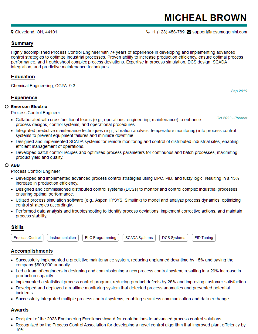
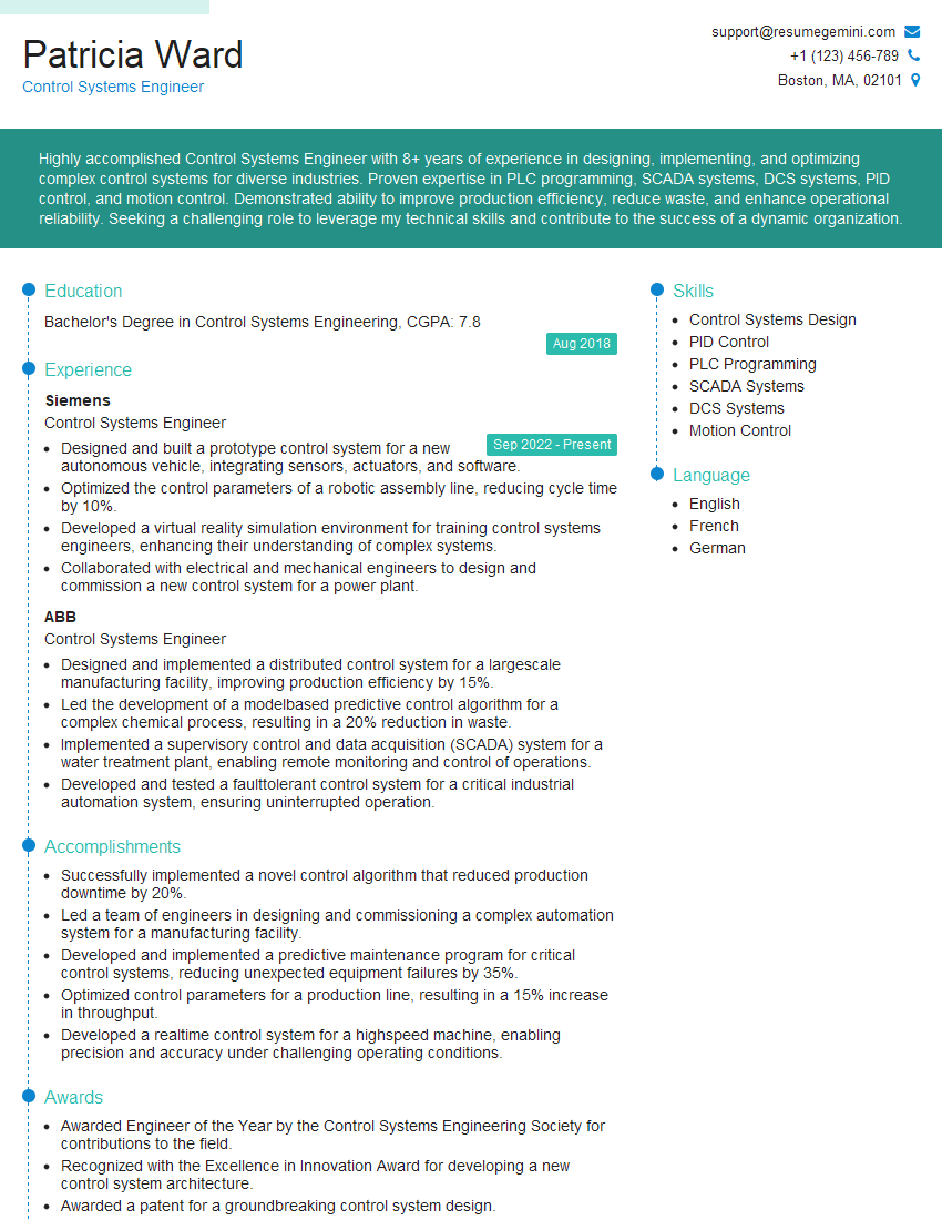
Mastering Electrical PLC Programming opens doors to exciting and rewarding careers in diverse industries. Demand for skilled PLC programmers is consistently high, offering excellent opportunities for career growth and advancement. To maximize your job prospects, creating a compelling and ATS-friendly resume is crucial. ResumeGemini is a trusted resource that can help you build a professional and effective resume tailored to highlight your skills and experience. Examples of resumes specifically designed for Electrical PLC Programming professionals are available, showcasing how to present your qualifications in the best possible light. Invest time in crafting a strong resume – it’s your first impression and a key to unlocking your future success.


Explore more articles
Users Rating of Our Blogs
Share Your Experience
We value your feedback! Please rate our content and share your thoughts (optional).
What Readers Say About Our Blog
To the interviewgemini.com Webmaster.
Very helpful and content specific questions to help prepare me for my interview!
Thank you
To the interviewgemini.com Webmaster.
This was kind of a unique content I found around the specialized skills. Very helpful questions and good detailed answers.
Very Helpful blog, thank you Interviewgemini team.