Interviews are more than just a Q&A session—they’re a chance to prove your worth. This blog dives into essential Knowledge of Pneumatics interview questions and expert tips to help you align your answers with what hiring managers are looking for. Start preparing to shine!
Questions Asked in Knowledge of Pneumatics Interview
Q 1. Explain the difference between pneumatic and hydraulic systems.
Both pneumatic and hydraulic systems use fluids to transmit power, but they differ significantly in the fluid used. Pneumatic systems use compressed air, while hydraulic systems use incompressible liquids like oil.
- Pneumatic Systems: Use compressed air, readily available and relatively safe. They are typically less powerful than hydraulic systems but offer advantages in speed and ease of control.
- Hydraulic Systems: Use oil under high pressure, resulting in greater force and power. They’re often chosen for heavy-duty applications but are more complex, require more maintenance, and pose greater safety concerns due to the high pressure and potential for leaks.
Think of it like this: a pneumatic system is like a strong but lightweight gust of wind, while a hydraulic system is like a powerful, steady stream of water from a fire hose.
Q 2. Describe the operation of a pneumatic cylinder.
A pneumatic cylinder is a linear actuator that converts compressed air energy into mechanical force and motion. It consists of a piston inside a cylinder, with air pressure applied to one side of the piston. This pressure difference forces the piston to move, extending or retracting the rod connected to it.
When air is supplied to one port (typically the ‘rod end’ or ‘cap end’ depending on the design), the piston moves in one direction. Releasing the pressure on that side and applying pressure to the opposite port reverses the piston’s movement. A pneumatic cylinder can be single-acting (moving only in one direction due to air pressure; return relies on springs or gravity) or double-acting (moving in both directions using pressurized air).
Imagine a bicycle pump: Pushing down on the handle compresses the air (analogous to applying air pressure), pushing the piston up. Releasing the handle allows the piston to return (analogous to venting pressure on one side and introducing it on the other).
Q 3. What are the advantages and disadvantages of using pneumatic systems?
Pneumatic systems offer several advantages, but also have some drawbacks:
- Advantages:
- Safety: Compressed air is generally safer than high-pressure hydraulic fluids.
- Cost-effectiveness: Relatively inexpensive components and simpler designs compared to hydraulics.
- Ease of maintenance: Less complex systems requiring less specialized maintenance.
- Speed and responsiveness: Air is compressible, allowing for quick changes in direction and speed.
- Disadvantages:
- Lower force capacity: Limited power output compared to hydraulic systems.
- Susceptibility to environmental factors: Performance can be affected by temperature and humidity.
- Air leakage: Leaks can reduce efficiency and create safety hazards.
- Noise: Compressed air can be noisy, particularly at high pressures.
For example, a robotic arm in a light assembly line might benefit from the speed and safety of a pneumatic system, while a heavy-duty press would likely require the power of a hydraulic system.
Q 4. How does a pneumatic valve work?
A pneumatic valve controls the flow of compressed air within a pneumatic system. They are typically actuated either manually (e.g., a simple lever valve), electrically (using solenoids), or pneumatically (using air pressure). The valve’s internal mechanism—spools, poppets, or diaphragms—redirect the flow of compressed air to different parts of the system, directing the movement of actuators like cylinders.
For instance, a three-way valve allows air to flow to either one of two outputs or to be vented. A four-way valve allows for bidirectional control of an actuator: Air pressure directs motion in one direction, while venting and applying air on the other side causes movement in the opposite direction.
Think of a garden hose with a tap (valve) controlling the water flow; similarly, a pneumatic valve controls the airflow in a pneumatic system, regulating its movement and direction.
Q 5. Explain the function of a pressure regulator.
A pressure regulator reduces and maintains a constant downstream pressure regardless of fluctuations in the upstream supply pressure. This is crucial for consistent performance of pneumatic components. It typically consists of a spring-loaded diaphragm or piston that adjusts an orifice to control the air flow.
Imagine a showerhead: You adjust the valve (pressure regulator) to get a comfortable water flow even if the water pressure at the main supply fluctuates due to other users in the building.
A pressure regulator ensures that a pneumatic system operates reliably at a predetermined pressure, even as the compressor output pressure changes, protecting sensitive components from excessive pressure and ensuring consistent performance.
Q 6. What is the purpose of a pneumatic filter?
A pneumatic filter removes contaminants like dust, oil, and water from the compressed air supply. This prevents damage to pneumatic components, ensures smooth operation, and extends their lifespan. Filters typically use porous materials to trap particles of different sizes.
Consider the air filter in your car’s engine: it prevents harmful particles from entering the engine and damaging it; similarly, a pneumatic filter protects sensitive pneumatic components from damage caused by contaminants in the compressed air.
Clean, dry air is essential for reliable pneumatic system operation; a filter is a critical component for maintaining that cleanliness and ensuring long-term performance.
Q 7. Describe different types of pneumatic actuators.
Pneumatic actuators convert compressed air energy into mechanical work. Several types exist:
- Pneumatic Cylinders: Linear actuators providing reciprocating motion (already described above).
- Rotary Actuators: Convert rotary motion through various mechanisms: vane motors, gear motors, or rack and pinion systems. Used for rotational movements.
- Grippers: Specialised actuators designed to grasp and manipulate objects. These can be pneumatic cylinders or more sophisticated mechanisms.
- Diaphragm Actuators: Utilize a flexible diaphragm that moves in response to air pressure changes. Used for applications requiring a sealing action or low-force movements.
The choice of actuator depends on the specific application requirements, such as the required force, speed, motion type (linear or rotary), and the overall design constraints.
Q 8. How do you troubleshoot a pneumatic leak?
Troubleshooting a pneumatic leak involves a systematic approach. Think of it like finding a leak in a water pipe – you need to locate the source to fix it. First, isolate the section of the system where the leak is suspected by listening carefully for hissing sounds. A simple soapy water solution applied to suspected joints and connections can help pinpoint the leak visually; bubbles will appear at the point of leakage. Once the leak is located, determine its cause. Common culprits include damaged seals (O-rings, gaskets), loose fittings, or worn-out components. Repairing involves replacing damaged seals or tightening loose fittings. If a component is faulty, it will require replacement.
Example: Imagine a robotic arm powered by pneumatics. If it’s moving slower than expected, a leak could be the culprit. By systematically checking connections, starting from the air compressor, and using soapy water, you can quickly find the leaking joint and replace the damaged O-ring.
Q 9. Explain the concept of pneumatic circuits.
A pneumatic circuit is a network of components that use compressed air to perform mechanical work. Think of it as a plumbing system for air, but instead of water, we have compressed air carrying the energy to actuate things like cylinders, valves, and motors. The circuit consists of air supply, control valves that regulate airflow, actuators (like pneumatic cylinders or motors) that do the work, and tubing connecting everything together. The design of a circuit dictates the sequence and timing of actions. We use schematic diagrams to visually represent these circuits, showing the flow of air and how components interact.
Example: A simple circuit might involve a pressure sensor, a 3/2-way valve, and a pneumatic cylinder. When the pressure sensor detects a certain threshold, the valve opens, allowing compressed air to flow into the cylinder, extending it and causing movement. When the threshold is no longer met, the valve closes.
Q 10. What are the safety considerations when working with pneumatic systems?
Safety is paramount when working with pneumatic systems. Compressed air is powerful and can cause serious injuries. Always use appropriate personal protective equipment (PPE), including safety glasses, hearing protection (air compressors can be noisy!), and gloves. Before working on any system, ensure the air supply is completely shut off and the pressure is relieved. Never point a pneumatic device at yourself or others. Regularly inspect components for wear and tear, and replace them if necessary to prevent unexpected failures. Understand the potential hazards of high-pressure air and take precautions to prevent sudden releases of pressure. Ensure the system is properly grounded to prevent static electricity build-up, and be aware of the potential for noise pollution and implement mitigation measures if necessary.
Example: Before servicing a pneumatic press, it’s crucial to completely de-energize the system, relieve pressure, and lock out the power source to prevent accidental activation.
Q 11. Describe the different types of pneumatic fittings.
Pneumatic fittings are crucial for connecting components within a pneumatic system. They ensure a leak-free, secure connection and are chosen based on factors like tube diameter, pressure rating, and material compatibility. Common types include:
- Push-to-connect fittings: These are quick and easy to use; the tube is pushed into the fitting, creating a secure seal.
- Compression fittings: A nut compresses a ferrule against the tube, creating a leak-tight seal. They’re robust and reusable.
- Flare fittings: The end of the tube is flared, creating a larger surface area that is tightened by a nut and sleeve. They are known for their high pressure capability.
- Threaded fittings: These use threaded connections, suitable for higher-pressure applications, and provide a robust connection.
Example: Push-to-connect fittings are ideal for smaller pneumatic systems where speed and ease of assembly are prioritized. Compression fittings would be preferred for higher-pressure applications that might need regular maintenance and disassembling.
Q 12. How do you calculate the flow rate of a pneumatic system?
Calculating the flow rate of a pneumatic system depends on several factors. The most common method involves using the following formula:
Flow Rate (SCFM) = (Cylinder Volume (cubic inches) / Cycle Time (seconds)) * (Pressure Ratio)where SCFM is standard cubic feet per minute, and Pressure Ratio is the ratio of the system pressure to standard atmospheric pressure.
Other factors influencing the flow rate include the size of the tubing, the presence of restrictions, and the type of air compressor used. Specialized flow meters can be used for accurate measurement.
Example: Let’s say a pneumatic cylinder needs 100 cubic inches of air to complete a cycle in 2 seconds at 100 PSI. In this case, the flow rate would be (100 / 2) * (100/14.7) ≈ 340 SCFM.
Note: This is a simplified calculation. More complex formulas may be needed depending on system specifics.
Q 13. What is the role of a pneumatic accumulator?
A pneumatic accumulator is a pressure vessel that stores compressed air, acting as a buffer or reservoir. Imagine it like a water tower for a pneumatic system. It helps to smooth out pressure fluctuations, reducing the workload on the air compressor. This is crucial for applications requiring consistent pressure despite fluctuating demands. Accumulators also help to absorb shocks and dampen pulsations in the air supply, improving the performance and longevity of downstream components. Furthermore, they can provide a reserve of energy in case of temporary compressor failure, ensuring continued operation for a short period.
Example: In a large manufacturing process using many pneumatic cylinders, an accumulator prevents the compressor from constantly cycling on and off, extending its lifespan and reducing energy consumption.
Q 14. Explain the function of a pneumatic relay.
A pneumatic relay, also known as a pneumatic amplifier, is a device that uses a small amount of control air to control a much larger amount of power air. Think of it as a lever for air. A small input signal actuates a pilot valve, which then controls the flow of a larger volume of compressed air to an actuator. This enables low-power control signals to operate high-power pneumatic actuators. Relays are essential for remote control of pneumatic systems and for increasing the power of the system using a small input signal.
Example: In a large clamping system, a small button push may actuate a pilot valve in a pneumatic relay. This relay then directs a much larger volume of compressed air to powerfully clamp a work piece.
Q 15. What are the common causes of pneumatic system failure?
Pneumatic system failures can stem from various sources, broadly categorized into component malfunctions, environmental factors, and design flaws. Let’s explore these in detail.
- Component Malfunctions: This is the most common cause. Leaks in hoses, fittings, or cylinders are frequent culprits. A leaky system loses pressure, leading to weak actuation or complete failure. Worn seals, damaged diaphragms in valves, and piston rod wear in cylinders all contribute. Compressor issues, like insufficient air supply or overheating, are also critical.
- Environmental Factors: Extreme temperatures can affect seals and lubricants, causing them to harden or degrade, leading to leaks. Moisture contamination can cause rust and corrosion in components, especially metal ones. Dust and debris can clog filters, restricting airflow and leading to pressure drops. External damage, like physical impact to hoses or components, can also cause failure.
- Design Flaws: Improper sizing of components (e.g., undersized cylinders for a given load) can lead to over-stress and premature failure. Poorly designed air distribution networks can create pressure drops or uneven airflow. Lack of proper safety features, like pressure relief valves, can result in catastrophic failures.
Example: I once worked on a system where a seemingly minor leak in a small fitting caused a significant pressure drop, leading to the failure of a large clamping cylinder. It took considerable time to isolate the leak because the system was poorly documented.
Career Expert Tips:
- Ace those interviews! Prepare effectively by reviewing the Top 50 Most Common Interview Questions on ResumeGemini.
- Navigate your job search with confidence! Explore a wide range of Career Tips on ResumeGemini. Learn about common challenges and recommendations to overcome them.
- Craft the perfect resume! Master the Art of Resume Writing with ResumeGemini’s guide. Showcase your unique qualifications and achievements effectively.
- Don’t miss out on holiday savings! Build your dream resume with ResumeGemini’s ATS optimized templates.
Q 16. Describe different types of pneumatic sensors.
Pneumatic sensors monitor various parameters within a pneumatic system. They’re crucial for feedback control and ensuring safe and efficient operation.
- Pressure Sensors: These measure the air pressure at various points in the system. They come in various types, such as piezoresistive, capacitive, and strain gauge based sensors, each offering different accuracy and pressure ranges. These are vital for monitoring system pressure and triggering safety shutdowns if pressure exceeds safe limits.
- Proximity Sensors: Used to detect the presence or absence of an object without physical contact. Inductive, capacitive, and photoelectric proximity sensors are frequently used to sense the position of pneumatic actuators or workpieces in automated systems.
- Flow Sensors: Measure the volume of compressed air flowing through a section of the system. This helps in detecting leaks or ensuring that sufficient airflow is available to meet the application’s needs.
- Temperature Sensors: These monitor the temperature of the compressed air and various system components. This is crucial because extreme temperatures can damage seals and other components. Thermostats can shut down the system if temperatures become unsafe.
Example: In a robotic arm application I worked on, proximity sensors were used to ensure that the gripper properly grasped the workpiece, preventing damage. Pressure sensors were used to monitor the clamping force.
Q 17. How do you select the appropriate pneumatic components for a given application?
Selecting appropriate pneumatic components requires a methodical approach. It’s crucial to consider several factors to ensure system reliability, efficiency, and safety.
- Operating Pressure: Determine the required system pressure for proper actuation. Components must have pressure ratings exceeding this requirement.
- Flow Rate: Calculate the necessary airflow to achieve the desired speed and response time. Undersized components will lead to slow response and potential stalling.
- Load Requirements: For actuators (cylinders), determine the force needed to move the load. The cylinder’s bore size and piston area must be sufficient to handle this force.
- Environmental Conditions: Consider temperature, humidity, and potential contamination. Select components with appropriate material properties and protection to withstand these conditions.
- Safety Requirements: Integrate safety features such as pressure relief valves, emergency stops, and limit switches to protect personnel and equipment.
Example: Choosing a cylinder requires calculating the required force based on the load weight, frictional forces, and acceleration. Then, selecting a cylinder with an adequate bore diameter to provide that force while considering the available operating pressure.
Q 18. Explain the concept of pneumatic logic.
Pneumatic logic uses compressed air to perform logical operations, similar to electronic logic but employing pneumatic components like valves and actuators. It allows for the creation of complex control systems for automated processes.
The basic elements are directional control valves that act as logic gates (AND, OR, NOT). These valves control the flow of compressed air to actuators based on the input signals. A system might use several valves arranged to implement desired logic sequences.
Example: A simple AND gate can be created using two 5/2 way directional valves. Both valves must receive a compressed air signal for the output to be activated. This could control a cylinder that only extends if two sensors confirm a certain condition.
More complex systems can be designed using various combinations of valves and logic functions, creating automated sequences such as assembly lines or material handling systems. These systems are often represented using pneumatic schematics similar to electrical circuit diagrams.
Q 19. How do you maintain a pneumatic system?
Maintaining a pneumatic system involves regular inspections, preventative measures, and timely repairs to ensure optimal performance and longevity.
- Regular Inspections: Check for leaks (using soapy water), worn seals, damaged hoses, and loose fittings. Inspect filters for blockages and replace them as needed.
- Lubrication: Proper lubrication is essential, especially for air cylinders and valves. Use the recommended type and amount of lubricant.
- Cleaning: Keep the system clean and free of dust and debris. Use compressed air (carefully) to blow out dust from components.
- Pressure Testing: Regular pressure testing ensures the system is operating within safe limits and identifies leaks early.
- Component Replacement: Replace worn or damaged components promptly. This is more cost-effective than waiting for catastrophic failures.
Example: During a scheduled maintenance check on a production line, I found a minor leak in a valve. Repairing this small leak prevented a potentially costly production disruption later.
Q 20. Describe your experience with pneumatic system design.
My experience with pneumatic system design spans over [Number] years, encompassing various industrial applications. I’ve been involved in designing systems for automated assembly lines, robotic manipulators, and material handling equipment.
My design process typically starts with a thorough understanding of the application requirements, including the load characteristics, speed requirements, and environmental factors. I then select appropriate components using sizing calculations, considering factors like pressure drops, flow rates, and safety margins. I’m proficient in using CAD software to create detailed system layouts and schematics.
Example: I recently designed a pneumatic system for an automated packaging line that involved coordinating several cylinders, valves, and sensors to ensure precise and reliable operation. The system incorporated safety features to prevent accidents during operation.
Q 21. Explain your experience with pneumatic system troubleshooting.
My troubleshooting approach is systematic and methodical. I utilize a combination of visual inspection, pressure testing, and logic analysis to pinpoint the source of the problem.
I begin by visually inspecting the system for obvious problems such as leaks, damaged components, or loose connections. Then I use pressure gauges to measure the system pressure at various points to identify pressure drops or blockages. Finally, I use my knowledge of pneumatic logic to trace the flow of compressed air and determine the faulty component. I utilize troubleshooting charts and diagrams to aid my analysis.
Example: I successfully resolved a production line standstill by identifying a faulty proximity sensor that was preventing a cylinder from operating correctly. I replaced the sensor, and the line was back in operation within minutes.
Q 22. How familiar are you with different pneumatic symbols and schematics?
I’m extremely familiar with pneumatic symbols and schematics. They’re the language of pneumatic systems, allowing engineers and technicians to communicate designs and troubleshoot problems effectively. My understanding encompasses both ISO 1219-1 (the international standard) and other commonly used symbol sets. I can readily interpret complex schematics, identify components, trace air flow, and understand the logical sequence of operations. For example, I can easily identify a double-acting cylinder from its symbol, differentiate between normally open and normally closed valves, and understand the role of various pressure regulators, filters, and lubricators in a system.
- ISO Symbols: I’m proficient in using the standardized ISO symbols for valves (e.g., 5/2, 3/2 way valves), actuators (cylinders, rotary actuators), and other pneumatic components. These symbols are essential for clear communication across different industries and engineering teams.
- Schematic Interpretation: I can interpret complex pneumatic schematics to understand system functionality, identify potential problems, and suggest design improvements. I can trace the flow of compressed air through the system and understand how different components interact.
Q 23. What software do you use for designing and simulating pneumatic systems?
Throughout my career, I’ve utilized several software packages for designing and simulating pneumatic systems. My experience includes:
- FluidSIM: This software is excellent for educational purposes and for designing relatively simple pneumatic circuits. Its intuitive interface makes it easy to create and simulate systems, visualizing air flow and component behavior.
- Autodesk Inventor: I use Inventor for creating detailed 3D models of pneumatic components and entire systems. This allows for accurate estimations of space requirements and ensures compatibility with other parts of the machinery. The simulation capabilities within Inventor allow for verifying designs before implementation.
- Pneumatic simulation software: Specific industry-standard simulation software tailored to pneumatic systems allows for more advanced analysis and validation of complex control loops and sequences. This includes modelling pressure drops, response times and energy consumption.
My proficiency extends beyond simple schematic design to encompass detailed simulations that predict system performance and identify potential issues before physical construction. This saves time, materials and reduces costs.
Q 24. Describe your experience with different types of pneumatic compressors.
My experience with pneumatic compressors covers various types, each with its strengths and weaknesses:
- Reciprocating Compressors: These are known for their high pressure capabilities but are less efficient and can produce pulsating airflow. I’ve worked on maintenance and troubleshooting of these compressors in industrial settings, addressing issues like valve wear, lubrication problems, and pressure fluctuations.
- Rotary Screw Compressors: These offer higher efficiency and smoother airflow compared to reciprocating compressors, making them suitable for large-scale applications. My experience includes assessing the performance of these compressors and optimizing their operation for energy efficiency.
- Rotary Vane Compressors: These provide a good balance between efficiency and cost. I’ve worked with them in various applications, understanding their limitations and maintenance needs.
- Centrifugal Compressors: These are typically used for very high-volume, lower-pressure applications. My knowledge includes understanding their applications and how to integrate them into larger compressed air systems.
I have experience selecting appropriate compressors based on application demands, considering factors like required pressure, flow rate, and duty cycle. I also understand the importance of regular maintenance to ensure the longevity and efficient operation of the compressor.
Q 25. How do you ensure the safety of pneumatic systems in a manufacturing environment?
Ensuring the safety of pneumatic systems in a manufacturing environment is paramount. My approach involves a multi-layered strategy:
- Pressure Relief Valves: These are crucial for preventing over-pressurization, which could lead to catastrophic failures. Regular inspection and testing are essential to guarantee their proper functioning.
- Emergency Shut-off Valves: Strategically located emergency shut-off valves allow for quick isolation of sections of the pneumatic system in case of leaks or emergencies. Easy accessibility and clear labeling are critical.
- Guardrails and Interlocks: Protecting moving parts is vital. Guardrails and interlocks prevent accidental contact with high-pressure components or moving actuators. I ensure these are properly designed and installed in compliance with relevant safety standards.
- Regular Maintenance and Inspections: A comprehensive maintenance schedule with regular inspections is fundamental to detecting potential hazards early on. This includes checking for leaks, wear and tear, and ensuring proper lubrication.
- Operator Training: Properly trained operators are essential for preventing accidents. Comprehensive training programs cover safe operating procedures, emergency protocols, and hazard recognition.
- Risk Assessments: Thorough risk assessments are conducted before commissioning any pneumatic system to identify potential hazards and implement appropriate control measures. This may involve using HAZOP (Hazard and Operability Study) methodologies.
Safety is not merely an afterthought; it’s integral to every stage of design, installation, and operation. It’s a core value that I consistently prioritize.
Q 26. Explain your experience with pneumatic control systems.
My experience with pneumatic control systems encompasses various levels of complexity, from simple on/off control to sophisticated programmable logic controllers (PLCs). I’m proficient in designing and implementing systems using:
- Basic Valves and Logic Gates: I can design systems using directional control valves, pressure regulators, and simple logic gates to achieve specific sequencing and control operations. This might involve implementing AND, OR, and NOT logic functions using pneumatic components.
- Proportional Valves and Feedback Control: For more precise control, I utilize proportional valves and integrate feedback mechanisms such as pressure sensors and position sensors to create closed-loop systems. This allows for fine-tuning control and maintaining accuracy. For example, I’ve designed such systems for regulating clamping force in automated assembly lines.
- PLC Integration: I’m experienced in integrating pneumatic systems with PLCs. This allows for more advanced control algorithms, automated sequences, and remote monitoring capabilities. I’ve used various PLC programming languages to develop control programs for sophisticated pneumatic operations.
I understand the importance of selecting appropriate control methods depending on system complexity and performance requirements, always considering factors such as accuracy, speed, and cost.
Q 27. What are some common problems encountered during the installation of pneumatic systems?
Several common problems can arise during the installation of pneumatic systems:
- Leaks: Leaks are a frequent issue, often stemming from improper fitting connections, damaged tubing, or worn components. Systematic leak detection using soap solution is crucial for identifying and addressing these problems.
- Improper Air Preparation: Neglecting proper filtration, regulation, and lubrication can lead to component damage, reduced performance, and system failure. Ensuring adequate air preparation is paramount.
- Incorrect Piping and Routing: Poorly routed air lines can lead to inefficient operation, increased pressure drops, and even safety hazards. Careful planning and consideration of space constraints are necessary.
- Insufficient Support: Inadequate support for tubing and components can cause vibration, fatigue, and potential failure. Providing sufficient support is essential for system reliability.
- Inconsistent Air Pressure: Fluctuations in air pressure can negatively impact system performance. The installation must incorporate appropriate pressure regulators and monitoring devices.
A thorough understanding of pneumatic principles and careful planning and execution are key to minimizing these installation challenges. Preventive maintenance and careful quality checks during installation are also critical.
Q 28. Describe your experience working with different pneumatic manufacturers’ products.
My experience encompasses a broad range of pneumatic manufacturers’ products, including:
- Festo: I’ve worked extensively with Festo’s range of pneumatic components, including their valves, cylinders, and control systems, appreciating their quality and wide selection. This extends to understanding their product catalogs and selecting components for different applications.
- SMC: SMC’s components are also frequently used in my projects. I’m familiar with their product lines and their strengths in different niches.
- Parker Hannifin: Parker Hannifin offers a comprehensive suite of pneumatic products, and I’ve incorporated their components into various designs, understanding their performance characteristics.
- Other Manufacturers: Beyond these major players, my experience encompasses a broader array of manufacturers whose components I’ve evaluated, selected and integrated based on specific project needs and cost-benefit analyses.
My understanding extends beyond merely using these components. I’m familiar with their respective technical specifications, maintenance recommendations, and typical application scenarios. This allows me to make informed decisions regarding component selection and integration.
Key Topics to Learn for Your Pneumatics Interview
Ace your next interview by mastering these fundamental concepts. We’ve broken down the key areas to ensure you’re prepared to showcase your expertise.
- Pneumatic System Components: Understand the function and interaction of compressors, air dryers, filters, regulators, valves (directional control, flow control, pressure regulators), cylinders, actuators, and tubing. Be prepared to discuss their selection criteria based on application requirements.
- Pneumatic Circuits and Schematics: Learn to read and interpret pneumatic circuit diagrams (schematics). Practice designing basic circuits for common applications, including understanding symbols and logic. Discuss your experience troubleshooting issues using these diagrams.
- Fluid Power Principles: Demonstrate a solid grasp of Pascal’s Law and its application in pneumatic systems. Be ready to explain concepts like pressure, flow, and volume, and how they relate to system performance.
- Safety and Maintenance: Discuss safety procedures related to working with compressed air, including proper handling of equipment and potential hazards. Explain common maintenance tasks and troubleshooting techniques for pneumatic systems.
- Applications of Pneumatics: Be ready to discuss real-world applications you’ve encountered or are familiar with. Examples include automation in manufacturing, robotics, material handling, and process control systems. Highlight your problem-solving skills in these contexts.
- Troubleshooting and Diagnostics: Explain your approach to diagnosing and resolving common issues in pneumatic systems. Discuss your experience with leak detection, pressure testing, and component replacement.
Next Steps: Unlock Your Career Potential
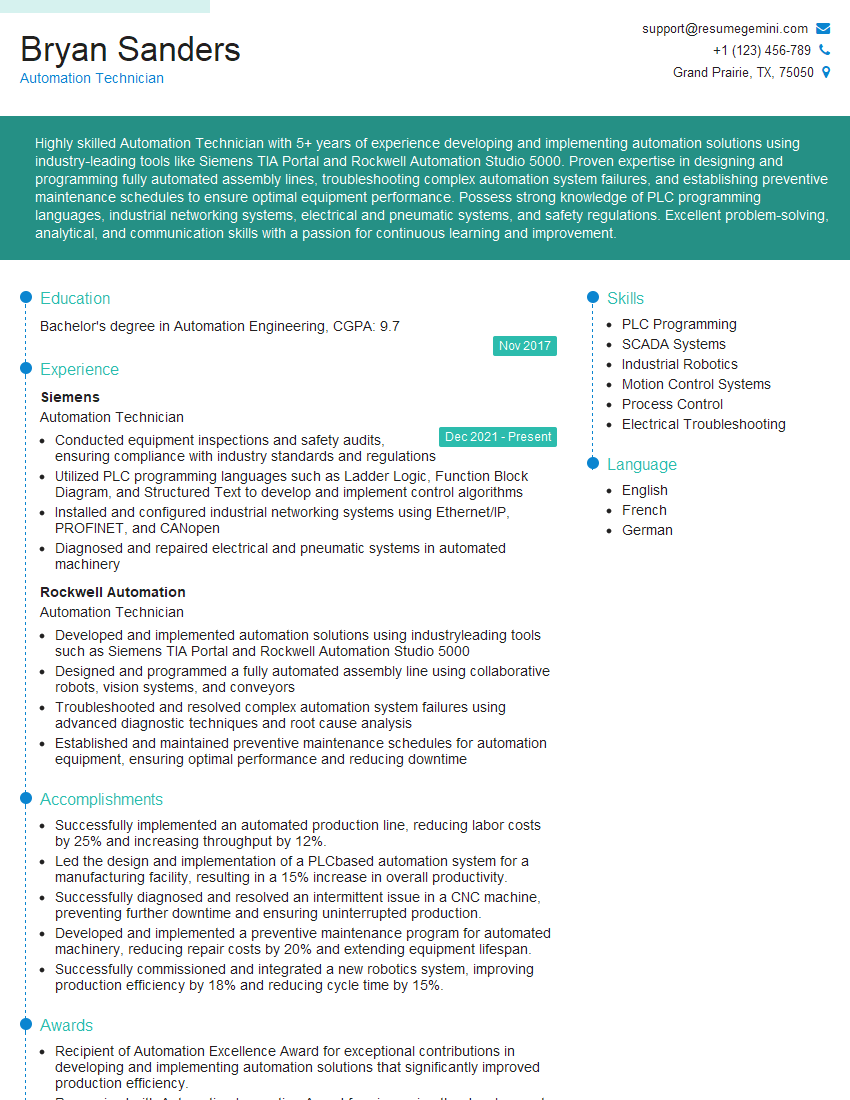
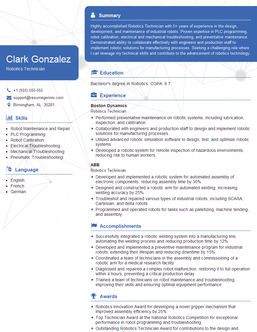
Mastering pneumatics opens doors to exciting career opportunities in a wide range of industries. To maximize your job prospects, a strong resume is crucial. Crafting an ATS-friendly resume that highlights your skills and experience is key to getting noticed by recruiters. We recommend using ResumeGemini to build a professional and effective resume tailored to your experience in pneumatics. ResumeGemini provides examples of resumes specifically designed for professionals with Knowledge of Pneumatics, ensuring your application stands out from the competition.
Explore more articles
Users Rating of Our Blogs
Share Your Experience
We value your feedback! Please rate our content and share your thoughts (optional).
What Readers Say About Our Blog
To the interviewgemini.com Webmaster.
Very helpful and content specific questions to help prepare me for my interview!
Thank you
To the interviewgemini.com Webmaster.
This was kind of a unique content I found around the specialized skills. Very helpful questions and good detailed answers.
Very Helpful blog, thank you Interviewgemini team.