Interviews are opportunities to demonstrate your expertise, and this guide is here to help you shine. Explore the essential Precise Measurement and Layout interview questions that employers frequently ask, paired with strategies for crafting responses that set you apart from the competition.
Questions Asked in Precise Measurement and Layout Interview
Q 1. Explain the concept of Geometric Dimensioning and Tolerancing (GD&T).
Geometric Dimensioning and Tolerancing (GD&T) is a symbolic language used on engineering drawings to define the size, shape, orientation, location, and runout of features on parts. It’s crucial for ensuring parts fit together correctly and function as intended, even with slight variations in manufacturing. Instead of relying solely on plus/minus tolerances for individual dimensions, GD&T uses symbols and zones to specify allowable deviations more precisely.
For instance, imagine a hole that needs to be precisely located on a part. Using only plus/minus tolerances might allow the hole to be slightly off-center, potentially causing problems when assembling it with another part. GD&T, however, allows us to define a circular zone around the nominal location of the hole. As long as the hole’s center falls within this zone, it’s considered acceptable, regardless of the individual hole diameter tolerance.
- Size Tolerance: This dictates the permissible variation in the size of a feature (diameter of a hole, length of a shaft).
- Form Tolerance: This covers the shape of a feature – straightness, flatness, circularity, cylindricity.
- Orientation Tolerance: This defines the allowable angular deviation of a feature from a datum reference (perpendicularity, parallelism, angularity).
- Location Tolerance: This specifies the allowable deviation of a feature’s location from a datum reference (position, concentricity).
- Runout Tolerance: This describes the allowable variation in the circularity and axiality of a rotating feature.
GD&T is essential for clear communication between designers, manufacturers, and inspectors, ensuring everyone understands the required precision and avoiding costly errors during production.
Q 2. Describe your experience with Coordinate Measuring Machines (CMM).
I have extensive experience operating and programming Coordinate Measuring Machines (CMMs), both bridge-type and articulated-arm types. My work involves inspecting complex parts, ranging from small precision components to large aerospace castings, ensuring they meet the specified tolerances defined by the GD&T on the engineering drawings. I’m proficient in using various CMM software packages to create inspection routines, collect data, and generate detailed reports analyzing dimensional accuracy.
In one project, I used a CMM to inspect turbine blades for a jet engine. The tolerances were extremely tight, requiring sub-micron accuracy. I developed a custom measurement program to analyze the blade’s profile, airfoil shape, and surface finish, ensuring that every blade met the rigorous quality standards for safe and efficient operation. Beyond data acquisition, I also identify potential systematic errors in the CMM itself and implement corrective actions. For example, I routinely perform probe calibrations and environmental checks (temperature and humidity) to maintain the highest level of accuracy and repeatability.
Q 3. What are the different types of measurement instruments used in precise layout?
Precise layout utilizes a range of instruments depending on the application and required precision. These include:
- Dial Calipers: Used for measuring outside and inside diameters, depths, and lengths with high precision.
- Micrometers: Provide extremely accurate linear measurements, often to thousandths or even ten-thousandths of an inch.
- Height Gauges: These measure vertical distances with great accuracy, often used in conjunction with surface plates.
- Optical Comparators: Used for detailed inspection of part geometry and comparing it to a master template.
- Laser Measurement Systems: These advanced tools offer non-contact measurement capabilities for high-speed and precise dimensional analysis.
- Digital Levels: Essential for establishing level and plumb lines, ensuring the accuracy of reference planes.
- Squares and Protractors: Used for angle measurement and verification of squareness and parallelism.
The selection of instruments is driven by the required level of accuracy, the size and complexity of the part, and the specific dimensions being measured. For instance, while dial calipers are adequate for some tasks, micrometers are essential when dealing with extremely tight tolerances.
Q 4. How do you ensure accuracy and precision in your measurements?
Ensuring accuracy and precision in measurements is paramount. This involves a multi-pronged approach:
- Proper Instrument Selection: Choosing the right tools for the job is crucial. Using an inappropriate instrument introduces errors.
- Calibration and Verification: Regularly calibrating instruments against known standards is essential to detect and correct drift or malfunctions. Traceability to national standards is ideal.
- Environmental Control: Maintaining stable temperature and humidity conditions minimizes thermal expansion and contraction effects on parts and instruments.
- Proper Measurement Technique: Following established procedures and using appropriate techniques (e.g., avoiding excessive force on calipers) minimizes human error.
- Multiple Measurements: Repeating measurements and calculating statistical parameters (mean, standard deviation) help identify outliers and quantify uncertainty.
- Data Analysis: Employing statistical process control (SPC) techniques helps detect trends and patterns in measurements, assisting in process improvement.
In my experience, meticulous attention to detail and a systematic approach significantly contribute to the reliability of measurement results.
Q 5. What are the common sources of error in precise measurement and how do you mitigate them?
Several factors can introduce errors into precise measurements:
- Instrument Error: This includes inherent inaccuracies in the instrument itself, wear and tear, or improper calibration.
- Environmental Error: Temperature, humidity, and vibrations can affect measurements.
- Human Error: Parallax error, incorrect reading of scales, and improper handling of instruments are common sources of human error.
- Part Variability: Variations in the manufacturing process can lead to deviations from the nominal dimensions of the part.
- Fixture Error: If a part is not properly fixtured during measurement, it can lead to errors.
Mitigation strategies include calibration, environmental control, training personnel on proper techniques, using appropriate fixturing, and applying statistical methods to analyze data and identify sources of error. For example, in a situation where temperature fluctuations are a concern, we could implement temperature compensation calculations or perform measurements in a temperature-controlled environment.
Q 6. Explain the process of creating a detailed layout drawing.
Creating a detailed layout drawing involves a structured process:
- Gathering Information: This includes reviewing engineering drawings, specifications, and any relevant documentation. Understanding the overall design intent is crucial.
- Defining Reference Planes: Establishing datum planes (reference points or surfaces) is fundamental for accurate location of features.
- Determining Feature Locations: Based on the specifications, accurately determine the location and orientation of each part feature.
- Selecting Scales and Units: Choosing appropriate scales ensures clarity and legibility of the drawing.
- Creating the Drawing: Employing CAD software, meticulously create the drawing, incorporating all necessary dimensions and annotations.
- Dimensioning and Tolerancing: Adding proper dimensions and GD&T symbols ensures accuracy and clarity in manufacturing.
- Review and Verification: Thoroughly reviewing the drawing for accuracy, completeness, and clarity is vital before releasing it.
The accuracy of the layout drawing directly impacts the manufacturing process. Any errors in the drawing can lead to costly rework or scrapped parts. This is why a systematic approach and careful attention to detail are crucial.
Q 7. How do you interpret engineering drawings and specifications?
Interpreting engineering drawings and specifications requires a thorough understanding of engineering principles and drafting practices. My approach involves:
- Understanding the Drawing Symbols and Conventions: Familiarity with industry standards (e.g., ASME Y14.5) is essential to understand the meaning of symbols, lines, and annotations.
- Identifying Key Dimensions and Tolerances: This includes recognizing both basic dimensions and GD&T symbols, understanding their significance for part functionality.
- Recognizing Datum References: Identifying the datum features, which are crucial for establishing the part’s orientation and location relative to other components.
- Analyzing Specifications: Carefully reviewing specifications ensures compliance with material requirements, surface finishes, and other critical parameters.
- Cross-Referencing Documentation: In some cases, other documents might need to be reviewed in conjunction with the drawings to get a complete understanding.
Misinterpreting drawings or specifications can lead to significant errors. Therefore, methodical review and verification are critical to ensure correct understanding before starting any manufacturing or inspection process.
Q 8. Describe your experience with CAD software (AutoCAD, SolidWorks, etc.).
My experience with CAD software spans over ten years, encompassing both 2D drafting in AutoCAD and 3D modeling in SolidWorks. I’ve used AutoCAD extensively for creating detailed engineering drawings, including precise annotations, dimensions, and tolerances. My proficiency extends to utilizing layers, blocks, and xrefs for efficient management of complex drawings. In SolidWorks, I’m skilled in creating and modifying 3D models, performing simulations, and generating detailed manufacturing drawings. I’m comfortable working with assemblies, generating bill of materials (BOMs), and using advanced features such as surface modeling and finite element analysis (FEA). For example, in a recent project involving the design of a precision robotic arm, I used SolidWorks to create the 3D model, perform kinematic simulations to verify its movement, and then generated detailed manufacturing drawings with tolerances in AutoCAD for the manufacturing team.
Beyond AutoCAD and SolidWorks, I possess working knowledge of other CAD packages like Creo Parametric and Inventor, adapting quickly to new software as needed. I’m also adept at utilizing various file formats (DXF, DWG, STEP, IGES) for seamless data exchange with other engineering teams and manufacturers.
Q 9. How do you handle discrepancies between design specifications and actual measurements?
Discrepancies between design specifications and actual measurements are a common challenge in precision engineering. My approach involves a systematic investigation to identify the root cause. First, I carefully re-check my own measurements, using multiple tools and techniques to eliminate human error. Then, I verify the accuracy of the measuring tools themselves – are they calibrated? Are they suitable for the measurement task? I examine the manufacturing process – were the tolerances achievable? Could there have been errors in the manufacturing process, such as improper machining or material variations?
Documentation is crucial. I meticulously record all measurements and observations. If the discrepancy is significant, I’ll initiate a formal deviation request, outlining the differences, their potential impact, and proposed corrective actions. This might involve modifying the design to accommodate the discovered inconsistencies, re-manufacturing components, or adjusting the tolerance limits in the design specifications. For instance, in a project involving the assembly of a high-precision optical instrument, we discovered a slight discrepancy in the lens mounting hole diameter. A thorough investigation revealed a minor calibration issue with the CMM (Coordinate Measuring Machine) used for inspection. Once corrected, the assembly proceeded without further problems.
Q 10. What are your experience with different types of measuring tools (e.g., calipers, micrometers, dial indicators)?
My experience with measuring tools is extensive. I’m proficient in using various instruments, including:
- Vernier calipers: For precise measurements of external and internal dimensions, depths, and step heights. I understand the importance of zeroing the calipers properly and avoiding parallax errors.
- Micrometers: For highly accurate measurements, typically in the micrometer range. I understand how to interpret the thimble scale and apply appropriate measuring techniques to minimize errors.
- Dial indicators: For measuring surface flatness, runout, and other geometric deviations. I know how to properly mount and zero the indicator, ensuring accurate readings.
- Coordinate Measuring Machines (CMMs): For accurate three-dimensional measurements of complex parts and assemblies. I have experience programming and operating various CMM types and interpreting the resulting measurement reports.
- Laser measurement tools: For non-contact measurements, such as distances and surface profiles. I’m familiar with the limitations and potential error sources associated with this technology.
I always select the appropriate measuring tool based on the required accuracy and the type of measurement. Regular calibration of all tools is paramount to maintain accuracy and traceability.
Q 11. How would you troubleshoot a measurement error?
Troubleshooting a measurement error is a systematic process. I follow these steps:
- Repeat the measurement: First, I repeat the measurement several times using the same tool to check for consistency. Random variations may indicate a normal level of measurement uncertainty.
- Use a different tool: If the results are inconsistent, I use a different measuring tool of similar or higher precision to confirm the reading.
- Check tool calibration: I verify the calibration of all the measuring tools used. An uncalibrated or improperly calibrated tool can lead to significant errors.
- Evaluate the measuring technique: I analyze the measurement process for potential errors in technique such as parallax error, incorrect zeroing, or improper tool handling.
- Check the part’s condition: I inspect the part for any surface imperfections, damage, or deformation that could affect the measurement.
- Consider environmental factors: Environmental conditions such as temperature and humidity can affect measurements, especially with sensitive instruments.
- Consult with colleagues: If the error persists, I consult with colleagues or experts to get a second opinion and identify other potential sources of error.
Thorough documentation is vital throughout the process. This helps to identify the root cause and implement corrective actions.
Q 12. Explain your understanding of tolerance analysis.
Tolerance analysis is the process of determining the allowable variation in dimensions and other parameters of a design, ensuring that the assembled part or product will function correctly within specified limits. It involves calculating the cumulative effect of individual tolerances on the overall functionality of a component or system.
There are several methods for tolerance analysis, including:
- Worst-case analysis: This method assumes that all tolerances will accumulate in the worst possible direction, leading to the most extreme deviation from the nominal value. This approach provides a conservative estimate of the overall tolerance but might be overly pessimistic.
- Statistical tolerance analysis: This more sophisticated method uses statistical distributions to model the variability of individual dimensions and predicts the distribution of the resulting overall dimension. It generally provides a more realistic assessment of the tolerance stack-up but requires more data.
A good understanding of tolerance analysis is crucial for ensuring that parts manufactured to within their individual tolerances will assemble correctly and perform their intended function. Failure to adequately consider tolerance analysis can lead to design failures, assembly problems, and increased manufacturing costs.
Q 13. Describe your experience with statistical process control (SPC).
My experience with Statistical Process Control (SPC) involves using various statistical techniques to monitor and control manufacturing processes. I’m proficient in creating and interpreting control charts (e.g., X-bar and R charts, p-charts, c-charts) to detect trends and variations in process parameters. This helps identify potential sources of process variation and implement corrective actions to improve quality and reduce defects. For example, in a recent project, I utilized control charts to monitor the diameter of machined parts. By analyzing the data, we were able to identify a machine malfunction before it resulted in a significant number of defective parts. This prevented costly rework and scrap.
I also understand the concepts of capability analysis (Cp, Cpk) to assess the ability of a process to meet its specifications. This allows for data-driven decisions on whether process improvements are necessary. The use of SPC ensures the production process remains stable and meets quality standards, resulting in reduced waste and increased customer satisfaction.
Q 14. How do you ensure the traceability of your measurements?
Traceability of measurements is critical for ensuring the accuracy and reliability of results. This involves maintaining a clear and unbroken chain of custody for all measurement equipment and processes. I ensure traceability by:
- Calibration certificates: I meticulously maintain calibration certificates for all measuring instruments. These certificates provide documented evidence of the instrument’s accuracy and traceability to national or international standards. Calibration intervals are strictly adhered to.
- Measurement procedures: I follow established measurement procedures, documenting each step of the measurement process. This ensures consistency and reduces the risk of errors.
- Data logging and recording: All measurement data is carefully recorded and stored, including the instrument used, date, time, and environmental conditions. This detailed documentation allows for verification and investigation in case of discrepancies.
- Traceable reference standards: We use traceable reference standards, which are themselves calibrated against national or international standards, to verify the accuracy of our measuring instruments.
This comprehensive approach establishes a verifiable chain of custody for all measurements, enabling accurate record keeping and promoting confidence in the reliability of our data.
Q 15. Explain your experience with different types of precision measuring equipment.
My experience with precision measuring equipment spans a wide range of instruments, each suited for specific tasks and accuracy requirements. I’m proficient with both traditional and advanced tools. For example, I routinely use:
- Vernier calipers: Excellent for measuring linear dimensions with high precision (typically to 0.01mm or 0.001 inch).
- Micrometers: Offering even higher precision than vernier calipers (typically to 0.002mm or 0.0001 inch), ideal for very small components.
- Dial indicators: Used to measure small displacements or variations in surface flatness; crucial for alignment checks and surface quality inspection.
- Optical comparators: These instruments use projection techniques to magnify and measure complex shapes with high accuracy, often used in quality control and inspection of machined parts.
- Coordinate Measuring Machines (CMMs): These are advanced, computer-controlled devices used for high-precision three-dimensional measurements, providing automated data capture for complex geometries.
- Laser measurement systems: Offering non-contact measurement capabilities for various applications, from distance measurement to dimensional verification of large components.
My expertise includes understanding the limitations and capabilities of each instrument, selecting the appropriate tool for the task, and interpreting the measurement data accurately.
Career Expert Tips:
- Ace those interviews! Prepare effectively by reviewing the Top 50 Most Common Interview Questions on ResumeGemini.
- Navigate your job search with confidence! Explore a wide range of Career Tips on ResumeGemini. Learn about common challenges and recommendations to overcome them.
- Craft the perfect resume! Master the Art of Resume Writing with ResumeGemini’s guide. Showcase your unique qualifications and achievements effectively.
- Don’t miss out on holiday savings! Build your dream resume with ResumeGemini’s ATS optimized templates.
Q 16. How do you create and maintain a calibrated measurement system?
Creating and maintaining a calibrated measurement system is critical for ensuring accuracy and reliability. It’s a multi-step process:
- Instrument Selection: Choose instruments with the required accuracy and precision for the application.
- Calibration Plan: Develop a schedule for regular calibration, considering factors like usage frequency and environmental conditions. Frequency is based on instrument type and manufacturer recommendations.
- Traceability: Ensure traceability to national or international standards. Calibration should be performed by a certified laboratory using traceable standards.
- Calibration Records: Maintain detailed records of each calibration, including dates, results, and any corrective actions taken. This documentation is crucial for quality control and regulatory compliance.
- Environmental Control: Maintain a stable environment to minimize the impact of temperature and humidity on measurement accuracy. This could involve using climate-controlled rooms for sensitive measurements.
- Regular Checks: Implement regular checks (e.g., using standard gauge blocks) between calibrations to detect any significant drift in measurement values.
- Preventive Maintenance: Follow manufacturer’s recommendations for cleaning and maintenance of instruments to ensure their optimal performance.
A well-maintained calibrated system minimizes measurement uncertainty and guarantees the reliability of results.
Q 17. What are the different types of measurement scales used?
Various measurement scales exist, each serving a specific purpose:
- Linear Scales: These are the most common, directly measuring length in units such as millimeters, inches, or meters.
- Angular Scales: Used to measure angles in degrees, minutes, and seconds (e.g., protractors, theodolites).
- Nominal Scales: These scales represent categories or qualities rather than quantitative measurements (e.g., hardness scales).
- Ordinal Scales: Rank data according to order (e.g., ranking customer satisfaction from low to high).
- Interval Scales: Measurements with equal intervals between values but no true zero point (e.g., temperature in Celsius or Fahrenheit).
- Ratio Scales: Measurements with equal intervals and a true zero point, enabling meaningful ratios (e.g., mass, length).
Understanding the type of scale being used is critical to accurately interpreting and utilizing measurement data. For example, you can’t meaningfully say that 20°C is twice as hot as 10°C because it’s an interval scale, but you can say that a 2kg object is twice as heavy as a 1kg object because it’s a ratio scale.
Q 18. Describe a situation where you had to make a precise measurement under challenging conditions.
I once had to measure the precise diameter of a turbine blade component within a high-temperature, vibration-prone environment. Standard instruments would be greatly affected by the conditions, affecting accuracy. To overcome this, I employed a laser displacement sensor capable of non-contact measurement. This minimized the risk of damage and ensured the accuracy and safety of the process. The system was calibrated before use and the measurements were carefully logged to account for thermal expansion of the blade. The data were then analyzed considering environmental factors to calculate a corrected diameter value.
Q 19. How do you document your measurements and findings?
Documentation is paramount in precise measurement. I use a structured approach:
- Measurement Logbook: A detailed physical or digital logbook containing all measurements, including date, time, instrument used, calibration information, environmental conditions (temperature, humidity), and any relevant observations.
- Data Sheets: Formal data sheets tailored to the specific measurement procedure, providing organized recording of measurements and calculations.
- Software and Spreadsheets: Data from CMMs and other automated systems are typically captured directly into software. Spreadsheets are invaluable for calculations and data analysis, allowing for plotting and trend analysis.
- Photographs and Diagrams: Visual documentation including photographs of the setup and detailed diagrams, especially useful for complex measurements.
- Traceability: Each measurement is linked to its source, instrument calibration, and any calculations applied.
This comprehensive system ensures the traceability and integrity of the measurement data, facilitating analysis and validation.
Q 20. What are the key considerations when selecting a measurement instrument?
Selecting the right measurement instrument requires careful consideration of several factors:
- Required Accuracy and Precision: The instrument’s accuracy and precision must meet or exceed the project’s requirements. Choose an instrument with a resolution and accuracy that is appropriate for the task.
- Measurement Range: The instrument’s range must encompass the expected values. The measurements must not approach the limitations of the measuring device.
- Resolution: The smallest increment the instrument can measure; it determines the level of detail.
- Environmental Conditions: Consider temperature, humidity, vibration, and other factors that might affect the measurement.
- Ease of Use and Operator Skill: Select an instrument that is user-friendly and matches the operator’s skill level.
- Cost and Availability: Balance cost with performance and availability, considering whether renting or purchasing is more suitable.
- Calibration Requirements: Consider the instrument’s calibration needs, frequency and costs.
Careful selection is crucial for obtaining reliable and accurate results.
Q 21. Explain the importance of calibration in precise measurement.
Calibration is fundamental to precise measurement. It’s the process of comparing a measuring instrument’s readings to a known standard, ensuring its accuracy. Without regular calibration, instruments drift, leading to inaccurate measurements and potentially costly errors. The importance can be illustrated by considering the consequences of an uncalibrated scale in a pharmaceutical setting – incorrect dosages could have serious health implications. Calibration provides:
- Accuracy: Confirms the instrument’s readings are within an acceptable range of the true value.
- Traceability: Establishes a chain of comparison back to national or international standards.
- Confidence: Increases confidence in the accuracy of the measurements and the reliability of the results.
- Compliance: Meets regulatory requirements and standards, especially in industries with strict quality control.
Regular calibration is an investment that protects against costly errors and ensures data integrity.
Q 22. How do you ensure the accuracy of your layout work?
Accuracy in layout work is paramount. It’s achieved through a multi-pronged approach that starts even before the first measurement is taken. It involves meticulous planning, the selection of appropriate tools and techniques, and rigorous verification at each stage.
- Careful Planning: This includes thoroughly reviewing blueprints, understanding tolerances (the acceptable range of deviation from a specified dimension), and anticipating potential challenges. A well-defined plan minimizes errors and rework.
- Calibration and Tool Selection: All measuring instruments – from tape measures and laser levels to total stations – must be calibrated regularly to ensure they provide accurate readings. The choice of tool is also crucial; for instance, a laser level offers greater precision than a spirit level for larger projects.
- Multiple Measurements and Cross-Checks: I always take multiple measurements from different reference points and use multiple methods to cross-check my work. This helps identify and eliminate human error or subtle inconsistencies in the environment.
- Documentation and Record Keeping: Detailed records of all measurements, calculations, and decisions made are essential for traceability and accountability. This also facilitates any necessary revisions or future reference.
For example, during a recent project involving the precise placement of HVAC equipment, I used a total station to establish precise coordinates, then triple-checked the measurements with a steel tape measure before proceeding. This layered approach ensured that the equipment was perfectly aligned.
Q 23. Describe your experience with different types of layout techniques.
My experience encompasses a wide range of layout techniques, adapting my approach to suit the specific project requirements and available resources. These include:
- Traditional Surveying Techniques: Using tape measures, levels, and theodolites for relatively smaller-scale projects, particularly where high precision is required but electronic equipment may be impractical.
- Laser Scanning and 3D Modeling: This technology is invaluable for complex projects, allowing for accurate digital representations of existing structures and enabling precise virtual layout planning before any physical work commences. This minimizes on-site errors and rework.
- GPS and GNSS Surveying: For large-scale projects or outdoor settings, GNSS (Global Navigation Satellite System) technology provides accurate positioning data, crucial for tasks like road construction or large-scale land surveying.
- Computer-Aided Design (CAD) and BIM (Building Information Modeling): I’m proficient in using CAD software to create detailed drawings and models, and BIM software for collaborative project management and visualization. These allow for precise coordination of different elements of a project.
I’ve successfully utilized these techniques on projects ranging from building renovations requiring precise demolition and rebuilding to large-scale infrastructure projects demanding accurate alignment and positioning.
Q 24. How do you handle complex and intricate layouts?
Complex layouts demand a structured and methodical approach. It’s about breaking down the larger problem into smaller, manageable components. This often involves:
- Establishing a Clear Reference Point: A well-defined, stable reference point is crucial. This could be a benchmark, a surveyed point, or even a precisely located feature of an existing structure.
- Modular Approach: Complex layouts are often tackled in modules or sections. This allows for focused attention on individual parts, minimizing the risk of errors and allowing for easier verification.
- Utilizing 3D Modeling: For extremely intricate work, creating a 3D model is exceptionally helpful for visualizing spatial relationships and potential clashes between different elements. This allows for the identification and resolution of potential issues before physical construction begins.
- Iterative Verification: Regular checks and verification throughout the process are vital to ensure that each module fits perfectly with the overall layout. Any discrepancies should be identified and rectified early on.
For instance, while working on the intricate layout of piping systems within a pharmaceutical manufacturing facility, we used 3D modeling to anticipate potential clashes and optimize the layout. This saved significant time and resources compared to a traditional trial-and-error approach.
Q 25. What software or tools are you proficient with for precise measurement and layout?
Proficiency with specialized software and tools is fundamental to my work. I am adept at using:
- AutoCAD: For creating and manipulating 2D drawings and plans.
- Revit: For Building Information Modeling (BIM), allowing for collaborative design and detailed project visualization.
- Total Stations and Laser Scanners: These provide highly accurate measurements in the field, crucial for large-scale projects.
- GPS/GNSS Receivers: For precise positioning, especially outdoors.
- Various Measurement Tools: Including steel tape measures, laser measuring tools, levels, and theodolites.
My proficiency extends beyond simply operating these tools; I understand their limitations and know how to choose the right tool for the job and interpret the data they provide accurately.
Q 26. Describe your experience with blueprint reading and interpretation.
Blueprint reading and interpretation is a core skill. It’s not just about understanding the symbols and dimensions but also grasping the overall design intent. My approach involves:
- Systematic Review: I meticulously review each sheet of the blueprint, paying close attention to details like scales, notations, and revision marks.
- Understanding Conventions: I’m familiar with various drafting conventions and symbols used across different disciplines (architectural, mechanical, electrical, etc.).
- Identifying Critical Dimensions and Tolerances: I carefully note down critical dimensions and associated tolerances to ensure that the layout adheres to specifications.
- Visualizing the 3D Structure: I can visualize the 3D structure from the 2D representations, anticipating potential challenges or conflicts early on.
In one instance, I identified a potential conflict in plumbing and electrical runs indicated on a set of blueprints that hadn’t been noted by the design team, preventing a costly and time-consuming alteration later in the project.
Q 27. How do you collaborate with other engineers and technicians on projects involving precise measurement and layout?
Collaboration is key in precise measurement and layout. I actively participate in team discussions, providing clear and concise information, actively listening to others’ perspectives, and ensuring that everyone understands the critical aspects of the layout. My approach includes:
- Clear Communication: I use clear and concise language to communicate technical information effectively to both technical and non-technical team members.
- Regular Check-Ins: Frequent check-ins with team members help maintain alignment and resolve any discrepancies early.
- Data Sharing: I use appropriate platforms and software for efficient data sharing, such as cloud-based storage and collaborative design tools.
- Active Listening and Feedback: I actively listen to feedback from team members and use it to refine the layout and improve its overall efficiency.
On a recent project, my collaboration with the structural engineer ensured that the placement of mechanical components did not compromise structural integrity, leading to a safe and efficient design.
Q 28. Describe a time when you had to make a critical decision related to a precise measurement or layout.
During the construction of a high-rise building, we encountered a discrepancy between the as-built survey data and the original design drawings concerning a critical support column. The discrepancy was within the tolerance, but ignoring it risked structural integrity.
After careful analysis of both the survey data and the original design documents, considering potential sources of error in both, and consulting with the structural engineer, I made the decision to recommend a slight adjustment to the support column’s position, opting for a more conservative approach. This involved explaining the situation, potential risks, and the proposed solution to the project manager and stakeholders. The adjustment was small but crucial, ensuring the building’s structural integrity and averting a potentially catastrophic failure.
This situation highlighted the importance of critical thinking, thorough data analysis, and clear communication in decision-making regarding precise measurements and layouts.
Key Topics to Learn for Precise Measurement and Layout Interview
- Units and Conversions: Mastering different units of measurement (pixels, points, ems, rems, percentages) and seamlessly converting between them. Understand the implications of each unit in responsive design.
- Grid Systems and Frameworks: Demonstrate a solid understanding of CSS Grid and Flexbox, including their strengths and weaknesses, and when to apply each. Experience with popular frameworks like Bootstrap or Tailwind CSS is beneficial.
- Responsive Design Principles: Explain your understanding of creating layouts that adapt seamlessly across different devices and screen sizes. Discuss media queries and their effective use.
- Typography and Visual Hierarchy: Show your knowledge of selecting appropriate typefaces, sizes, and line heights to create clear visual hierarchy and enhance readability. Understanding kerning and leading is advantageous.
- Layout Techniques: Be prepared to discuss various layout techniques, such as float-based layouts, absolute positioning, and relative positioning. Understand their pros and cons and best practices for each.
- Accessibility Considerations: Showcase your knowledge of creating accessible layouts that cater to users with disabilities. Discuss semantic HTML and ARIA attributes.
- Cross-Browser Compatibility: Explain your strategies for ensuring consistent layout and functionality across different web browsers. Discuss debugging techniques for cross-browser inconsistencies.
- Performance Optimization: Demonstrate an understanding of optimizing layout performance for faster loading times and improved user experience. This includes techniques like image optimization and efficient CSS usage.
- Version Control (e.g., Git): Familiarity with using Git for collaborative development and managing code changes is a valuable asset.
Next Steps
Mastering precise measurement and layout is crucial for building clean, efficient, and user-friendly websites, significantly enhancing your career prospects in web development. A well-crafted, ATS-friendly resume is your key to unlocking these opportunities. To present your skills effectively, consider leveraging ResumeGemini, a trusted resource for building professional resumes. ResumeGemini provides examples of resumes tailored to Precise Measurement and Layout, helping you showcase your expertise and land your dream job. Invest the time to create a strong resume – it’s an investment in your future success.
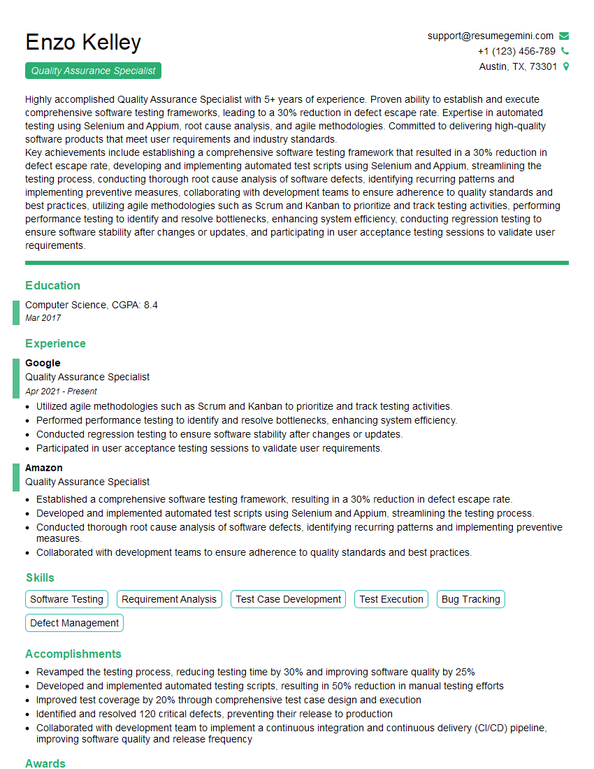
Quality Assurance Specialist Resume Sample
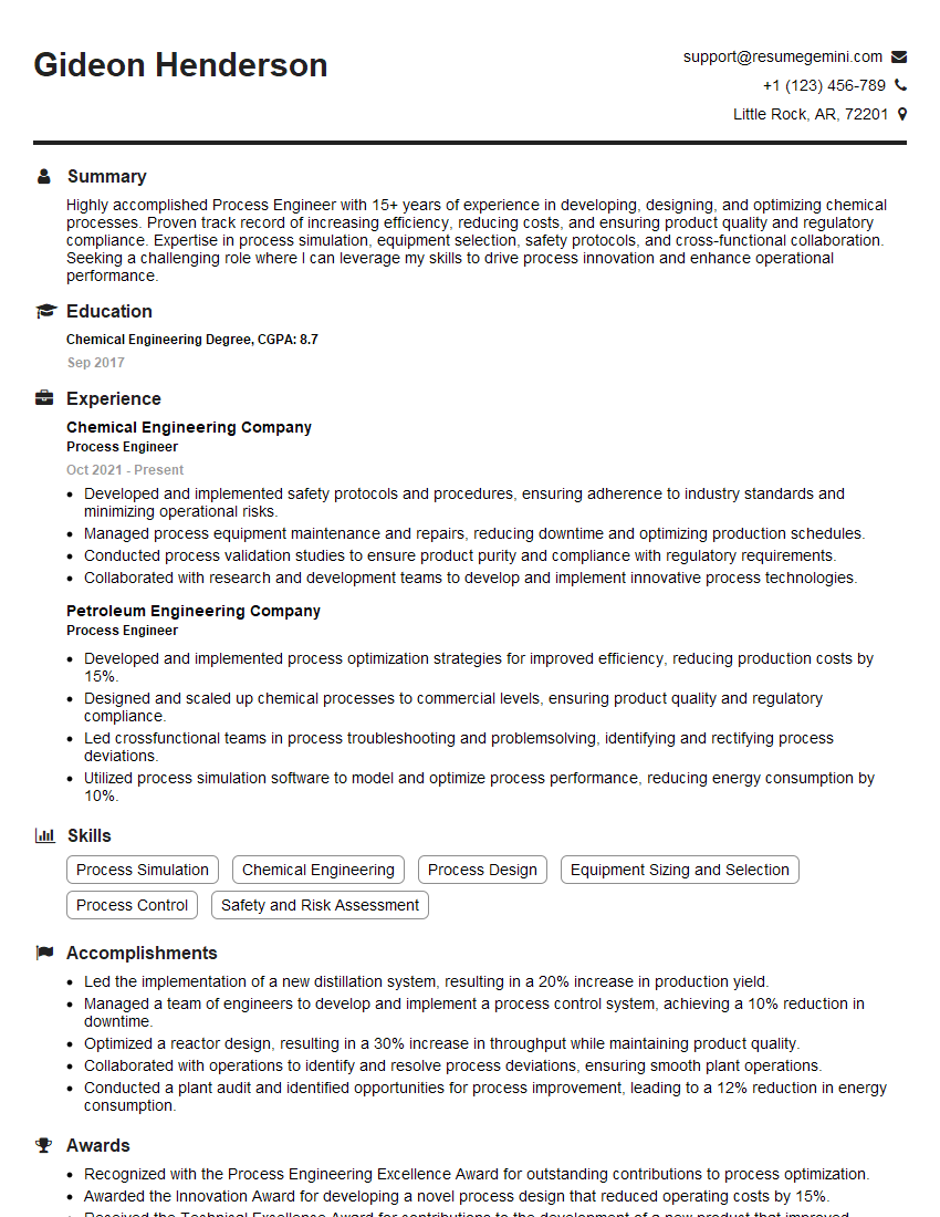
Process Engineer Resume Sample

Drafting Technician Resume Sample
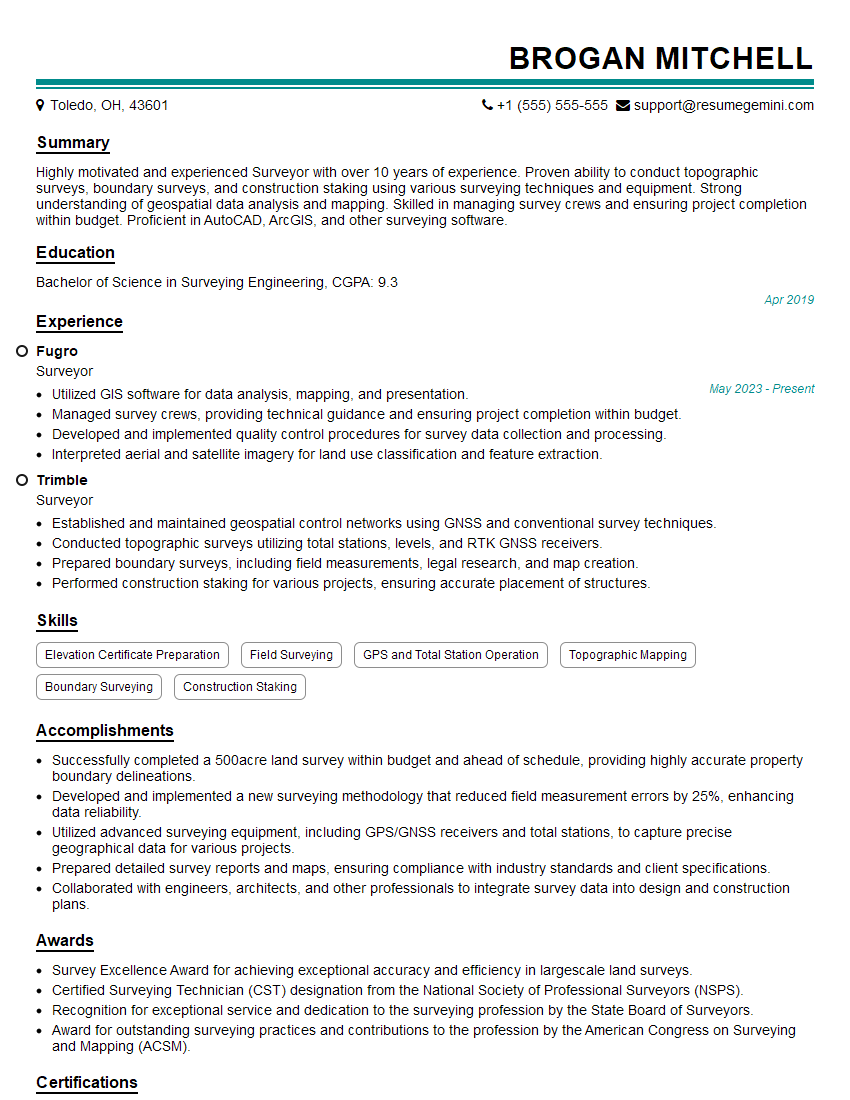
Surveyor Resume Sample
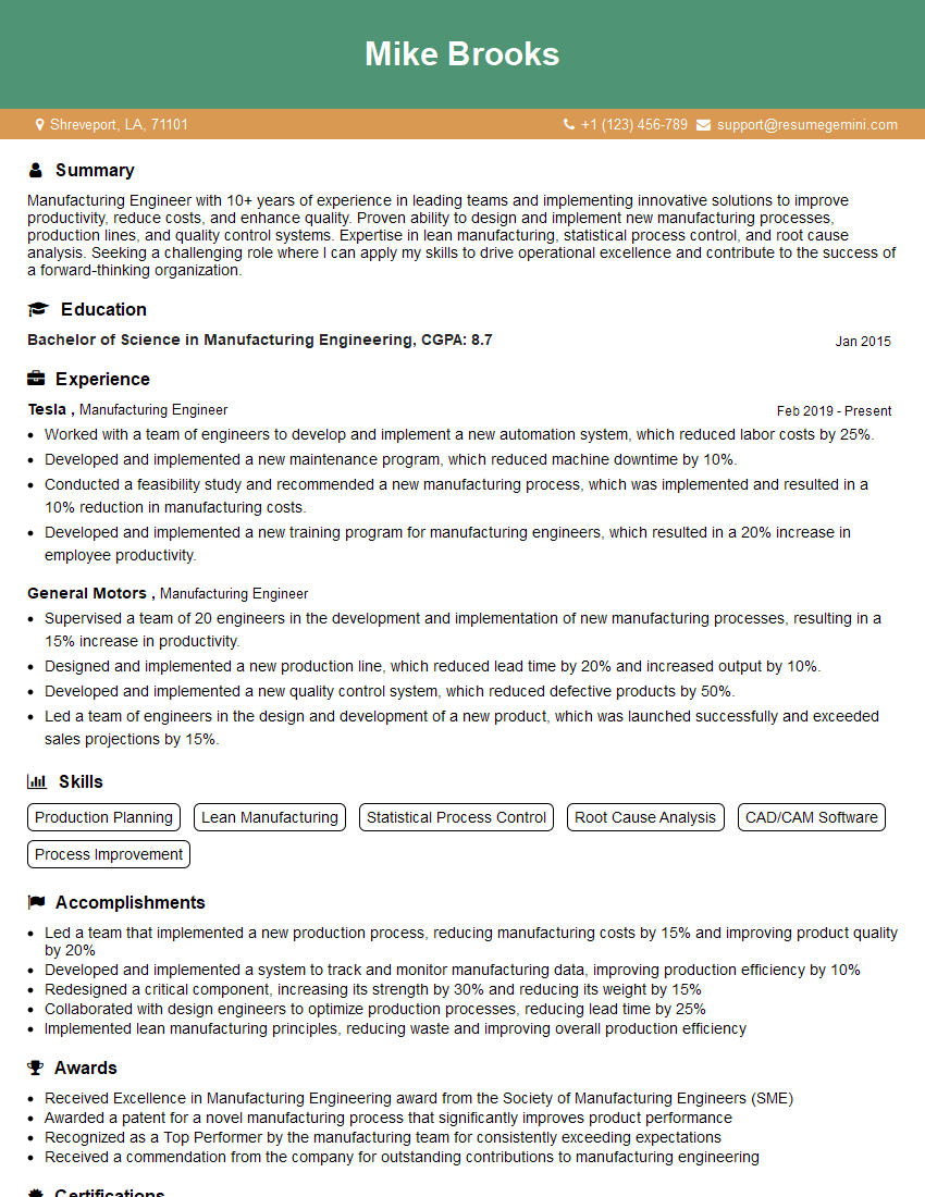
Manufacturing Engineer Resume Sample
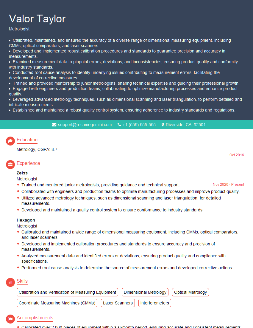
Metrologist Resume Sample
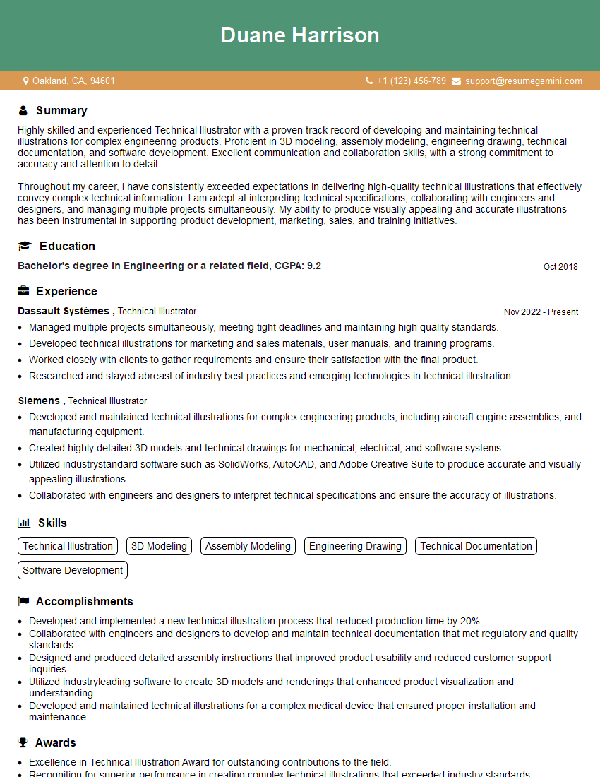
Technical Illustrator Resume Sample
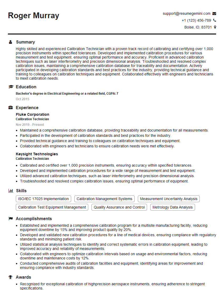
Calibration Technician Resume Sample
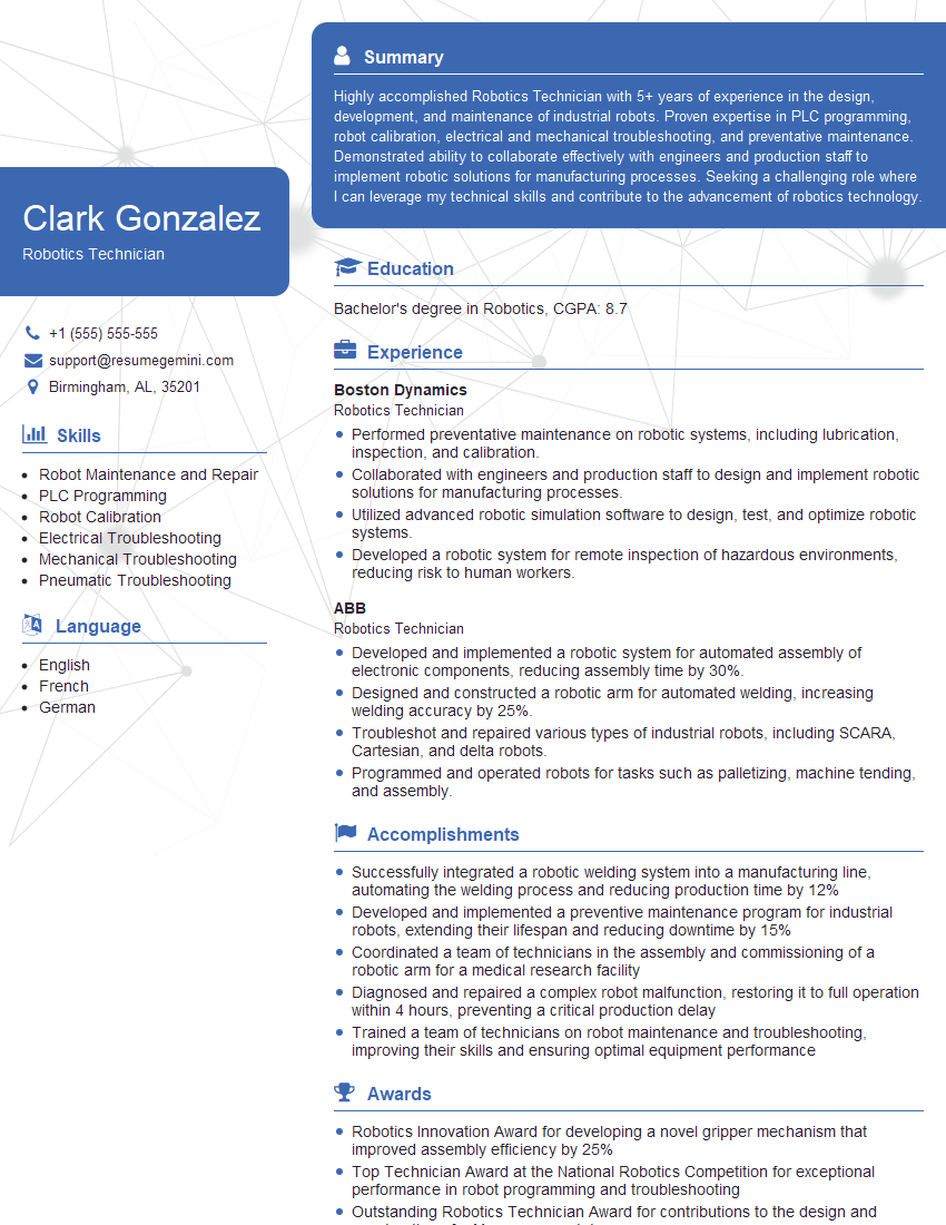
Robotics Technician Resume Sample
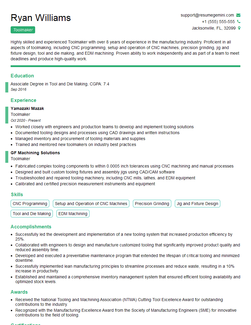
Toolmaker Resume Sample
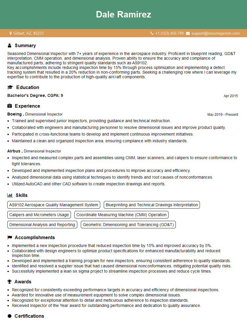
Dimensional Inspector Resume Sample

Quality Control Inspector Resume Sample
Explore more articles
Users Rating of Our Blogs
Share Your Experience
We value your feedback! Please rate our content and share your thoughts (optional).
What Readers Say About Our Blog
To the interviewgemini.com Webmaster.
Very helpful and content specific questions to help prepare me for my interview!
Thank you
To the interviewgemini.com Webmaster.
This was kind of a unique content I found around the specialized skills. Very helpful questions and good detailed answers.
Very Helpful blog, thank you Interviewgemini team.