The thought of an interview can be nerve-wracking, but the right preparation can make all the difference. Explore this comprehensive guide to Transformer Operation interview questions and gain the confidence you need to showcase your abilities and secure the role.
Questions Asked in Transformer Operation Interview
Q 1. Explain the principle of operation of a transformer.
A transformer is a static device that transfers electrical energy between two or more circuits through electromagnetic induction. It operates on the principle of Faraday’s Law of Electromagnetic Induction, which states that a changing magnetic field induces a voltage in a nearby conductor. In a transformer, this is achieved by using two or more coils of wire wound around a common ferromagnetic core. The coil connected to the input voltage source is called the primary winding, and the coil connected to the load is called the secondary winding. When an alternating current (AC) flows through the primary winding, it creates a fluctuating magnetic field in the core. This changing magnetic field then induces a voltage in the secondary winding, which is proportional to the number of turns in each winding.
Think of it like this: imagine two flashlights connected by a flexible rubber band. When you shake one flashlight (primary winding), the rubber band (magnetic field) transmits the movement to the other flashlight (secondary winding), causing it to light up albeit potentially brighter or dimmer depending on the flexibility and length of the rubber band.
The voltage transformation ratio (Vs/Vp) is directly proportional to the turns ratio (Ns/Np), where Vs and Vp are the secondary and primary voltages, and Ns and Np are the number of turns in the secondary and primary windings, respectively. This relationship allows transformers to step up (increase) or step down (decrease) voltage levels as needed.
Q 2. Describe the different types of transformers.
Transformers come in various types, categorized based on their core construction, application, and winding configuration. Here are some key types:
- Power Transformers: Used in power systems for stepping up or down voltage levels for transmission and distribution. These are typically large, robust transformers designed for high power handling capacity.
- Distribution Transformers: Smaller transformers used to step down voltage from high-voltage distribution lines to lower voltages for residential and commercial use.
- Instrument Transformers: Used to measure high voltages and currents safely. These include current transformers (CTs) and potential transformers (PTs).
- Autotransformers: Have a single winding with a common tap, providing voltage transformation with fewer windings than a conventional transformer. They are often used for voltage regulation.
- Isolation Transformers: Provide electrical isolation between the primary and secondary circuits, eliminating ground currents and improving safety.
- Pulse Transformers: Designed to handle short duration, high-energy pulses. Often found in applications like radar and switching power supplies.
Q 3. What are the key components of a power transformer?
The key components of a power transformer are:
- Core: Made of laminated ferromagnetic material (e.g., silicon steel) to minimize eddy current losses. The core provides a path for the magnetic flux.
- Primary Winding: The coil connected to the input voltage source.
- Secondary Winding: The coil connected to the load.
- Insulation: Various insulating materials (e.g., paper, oil, resins) are used to prevent short circuits and provide electrical protection.
- Tank: Encloses the core and windings, providing protection and containing the insulating oil.
- Bushings: Insulated terminals that provide safe connection points for the primary and secondary windings.
- Conservator Tank (optional): Used in oil-filled transformers to accommodate thermal expansion and contraction of the oil.
- Cooling System (optional): Various cooling systems, such as radiators, fans, or oil pumps, are used to dissipate heat generated within the transformer.
Q 4. Explain the concept of transformer efficiency and losses.
Transformer efficiency is the ratio of output power to input power, expressed as a percentage. Ideally, a transformer should have 100% efficiency, but in reality, losses occur, reducing efficiency. These losses can be categorized into:
- Iron Losses (Core Losses): These losses occur in the transformer core and are primarily due to hysteresis and eddy currents. Hysteresis losses are caused by the repeated magnetization and demagnetization of the core material, while eddy current losses are due to circulating currents induced in the core by the changing magnetic field.
- Copper Losses (I2R Losses): These losses occur in the windings due to the resistance of the copper wire. They are proportional to the square of the current flowing through the windings.
- Stray Losses: These are minor losses due to leakage flux and other factors.
High efficiency is crucial for minimizing energy waste and operating costs. Transformer design focuses on minimizing losses through the use of high-quality core materials, low-resistance windings, and efficient cooling systems. For instance, using high-grade silicon steel for the core minimizes hysteresis and eddy current losses.
Q 5. How do you calculate the voltage regulation of a transformer?
Voltage regulation refers to the change in secondary voltage from no-load to full-load conditions, expressed as a percentage. It’s a measure of the transformer’s ability to maintain a constant output voltage despite changes in load. The formula for voltage regulation is:
Voltage Regulation (%) = [(Vnl - Vfl) / Vfl] x 100
Where:
Vnlis the secondary voltage at no load.Vflis the secondary voltage at full load.
A lower voltage regulation indicates better performance, as the output voltage remains closer to its nominal value even under load. Factors influencing voltage regulation include the transformer’s impedance, load power factor, and load current.
Q 6. Describe different transformer cooling methods.
Transformer cooling methods are designed to dissipate the heat generated within the transformer, preventing overheating and extending its lifespan. Common methods include:
- Natural Air Cooling (AN): The transformer dissipates heat naturally through convection and radiation.
- Forced Air Cooling (AF): Fans are used to force air over the transformer’s surface, enhancing heat dissipation.
- Oil-Natural Air Cooling (ONAN): The transformer is immersed in oil, which circulates naturally to transfer heat to the tank and then to the surrounding air.
- Oil-Forced Air Cooling (OFAF): Oil circulates naturally, and fans force air over the tank to enhance cooling.
- Oil-Forced Air-Forced Oil Cooling (OFAFO): Both oil and air circulation are forced to improve cooling efficiency.
- Water Cooling: Water is circulated through coils or pipes to cool the oil or the transformer tank.
The choice of cooling method depends on the transformer’s size, power rating, and ambient temperature. Large power transformers often use sophisticated cooling systems like OFAF or OFAFO to manage the significant heat generation.
Q 7. What are the common faults found in transformers?
Transformers can experience various faults throughout their operational lifespan. Some common faults include:
- Winding Faults: These include short circuits between turns within a winding, or between windings, often caused by insulation breakdown due to overheating or aging.
- Core Faults: These can involve damage to the core laminations, leading to increased losses or noise.
- Overheating: Excessive heat generation can degrade insulation, leading to winding faults or even fires. This can result from overloading, faulty cooling systems, or blocked ventilation.
- Oil Leakage: Leakage from the transformer tank can compromise insulation and cooling.
- Bushings Failures: Damage or degradation of bushings can compromise the insulation and lead to insulation failures.
- Tap Changer Problems: Malfunction of the tap changer, which controls the output voltage, can impact voltage regulation.
Regular maintenance, including oil analysis, insulation testing, and thermal imaging, is crucial for detecting and preventing these faults, ensuring reliable and safe transformer operation.
Q 8. How do you perform a transformer oil test?
Transformer oil testing is crucial for assessing the condition and ensuring the reliable operation of power transformers. These tests help detect contaminants and degradation, preventing potential failures. Several tests are performed, including:
- Dielectric Strength Test: This measures the oil’s ability to withstand high voltage without breakdown. A lower dielectric strength indicates contamination or degradation, posing a risk of internal arcing.
- Interfacial Tension Test: This assesses the oil’s ability to separate from water. High moisture content significantly reduces the oil’s dielectric strength.
- Acidity Test: Determines the level of acidic components. Increased acidity accelerates the aging process of the oil and the transformer’s insulation.
- Dissolved Gas Analysis (DGA): This is a critical test that analyzes the gases dissolved in the oil, revealing potential faults within the transformer (discussed further in the next question).
- Viscosity Test: Measures the oil’s thickness, which impacts its ability to cool the transformer effectively.
The specific tests conducted depend on the transformer’s age, operating conditions, and the maintenance schedule. Regular oil testing allows for proactive maintenance, preventing catastrophic failures and extending the transformer’s lifespan. For example, detecting high acidity early on might prompt an oil filtration process before more extensive damage occurs.
Q 9. Explain the significance of Dissolved Gas Analysis (DGA) in transformer maintenance.
Dissolved Gas Analysis (DGA) is a cornerstone of transformer maintenance. It involves analyzing the gases dissolved in the transformer oil to identify potential internal faults. These gases are formed due to various breakdown processes within the transformer, such as overheating, partial discharges, and arcing.
Different gases indicate different fault types:
- Hydrogen (H2): Often indicates arcing or overheating.
- Methane (CH4): Suggests overheating of cellulose insulation.
- Ethane (C2H6): Points to more severe overheating than methane.
- Ethylene (C2H4): Indicates severe overheating or arcing.
- Acetylene (C2H2): A strong indicator of arcing and a serious fault.
By interpreting the gas ratios and concentrations, engineers can diagnose the type and severity of the fault, enabling timely intervention. For instance, a high concentration of acetylene would necessitate immediate action, possibly requiring transformer repair or replacement. DGA is not merely diagnostic; it’s a predictive tool, allowing proactive maintenance rather than reactive repairs after a catastrophic failure.
Q 10. Describe the process of transformer tap changing.
Transformer tap changing allows for voltage regulation, compensating for variations in voltage on the power grid or adjusting for load fluctuations. There are two main types of tap changers:
- On-load tap changers (OLTC): These allow for tap changes while the transformer remains energized, minimizing service interruptions. They use a sophisticated mechanism that makes and breaks connections under load, typically involving a rotating selector switch and diverter switches.
- Off-load tap changers: These require de-energizing the transformer before changing taps, resulting in downtime. They are simpler in design but less convenient.
The tap changer mechanism operates by selecting different windings within the transformer’s windings, effectively altering the turns ratio. This changes the output voltage proportionally. The process is precisely controlled to ensure safety and prevent damage to the equipment. Regular maintenance and inspection of the tap changer are vital to guarantee its reliable operation. A failure in the tap changer mechanism could lead to significant voltage instability and potential damage to connected equipment.
Q 11. What safety precautions should be taken when working with high-voltage transformers?
Working with high-voltage transformers demands strict adherence to safety protocols. The potential for serious injury or death is significant. Key precautions include:
- Lockout/Tagout Procedures: Complete isolation and de-energization of the transformer, verified with appropriate testing equipment before any work commences. This is paramount to avoid accidental energization.
- Personal Protective Equipment (PPE): Appropriate PPE, including insulated gloves, safety glasses, arc flash suits, and safety footwear, is essential.
- Grounding: Thorough grounding of the transformer and all related equipment to prevent electrical shock. Grounding prevents the accumulation of static charge and provides a low-impedance path for fault currents.
- Trained Personnel: Only qualified and authorized personnel trained in high-voltage safety procedures should work on or near high-voltage transformers. This includes having adequate understanding of safety procedures, potential hazards, and emergency response procedures.
- Permit-to-Work System: Following a formalized permit-to-work system to document the work, control access, and ensure safety procedures are followed.
Ignoring even one of these precautions can have disastrous consequences. Safety should always be the top priority when working with high-voltage transformers.
Q 12. Explain the importance of grounding in transformer operation.
Grounding is critical for the safe and reliable operation of transformers. It serves multiple vital functions:
- Safety: Grounding provides a low-impedance path for fault currents, diverting them to earth and preventing dangerous voltage build-up on exposed conductive parts. This minimizes the risk of electric shock to personnel.
- Overvoltage Protection: Grounding helps dissipate transient overvoltages caused by lightning strikes or switching surges. These surges can damage the transformer’s insulation if not effectively grounded.
- System Stability: Proper grounding helps maintain system stability by preventing ground faults from causing widespread outages.
- Lightning Protection: Grounding, combined with surge arresters, is crucial for protecting the transformer from lightning strikes, which can generate extremely high voltages.
The grounding system usually involves a robust grounding grid connected to the transformer’s tank and other conductive parts. The design and implementation of the grounding system are crucial; inadequate grounding can severely compromise safety and reliability. Imagine a scenario where a lightning strike hits a poorly grounded transformer – a major failure could result, potentially causing a significant outage and damage to the equipment.
Q 13. How do you perform a transformer impedance test?
Transformer impedance testing measures the transformer’s internal impedance, a crucial parameter for determining its short-circuit current capability and voltage regulation characteristics. This is typically done using a short-circuit test.
The procedure usually involves:
- Short-circuiting the secondary winding: The secondary winding is shorted using heavy conductors with low resistance.
- Applying a reduced voltage to the primary winding: A reduced voltage is applied to the primary winding until rated current flows in the secondary winding.
- Measuring voltage, current, and power: The primary voltage (Vsc), primary current (Isc), and power (Psc) are measured.
- Calculating impedance: The impedance (Zsc) is calculated using the formula:
Zsc = Vsc / Isc. The impedance can also be expressed as a percentage of the rated impedance.
This test helps determine the transformer’s capability to withstand short circuits, helps verify transformer nameplate data, and contributes to protection system settings. Accurate impedance measurement is crucial for proper coordination of protection relays and circuit breakers. A higher-than-expected impedance might suggest internal problems within the transformer.
Q 14. What is the role of a Buchholz relay in transformer protection?
A Buchholz relay is a protective device used in oil-filled power transformers. It’s a gas-operated relay that detects faults within the transformer, such as internal arcing or overheating, by sensing the presence of gases and/or abnormal pressure changes in the transformer’s conservator tank.
It operates based on two main principles:
- Gas Accumulation: If a fault occurs, gases are generated, accumulating in the relay’s chamber. When a predetermined amount of gas is accumulated, the relay activates, typically by tripping an alarm or initiating a shutdown of the transformer.
- Rapid Gas Evolution: In severe faults involving sudden arcing, a rapid evolution of gas occurs. The relay senses this abrupt increase in gas flow, triggering an immediate transformer shutdown.
The Buchholz relay is a vital safety device, preventing catastrophic damage to the transformer and potentially avoiding fire hazards or other significant incidents. It acts as an early warning system, providing ample time for investigation and remedial action. It’s a crucial component of a comprehensive transformer protection scheme.
Q 15. Describe the different types of transformer protection schemes.
Transformer protection schemes are crucial for ensuring the reliable and safe operation of transformers. They are designed to detect and respond to various faults, preventing damage and minimizing downtime. Several schemes are employed, often in combination, depending on the transformer’s size, location, and criticality.
- Differential Protection: This is the most common and effective scheme. It compares the currents entering and leaving the transformer. Any significant difference indicates an internal fault, triggering the protection relay to isolate the transformer.
- Overcurrent Protection: This simple scheme protects against excessive current flow, which could be due to short circuits or overloading. It uses current transformers to measure the current and trip the circuit breaker if a preset limit is exceeded.
- Buchholz Relay Protection: This is a gas-operated relay placed within the transformer’s conservator tank. It detects the presence of gases produced by internal faults like arcing or overheating, triggering an alarm or tripping the breaker.
- Temperature Protection: This scheme uses temperature sensors (e.g., winding temperature detectors) to monitor the transformer’s operating temperature. If the temperature exceeds a safe limit, it triggers an alarm or initiates cooling measures, potentially leading to a trip if the overheating persists.
- Ground Fault Protection: This protects against faults to ground within the transformer windings. It monitors for ground currents and trips the breaker if a fault is detected.
- Reflected Wave Protection: Advanced schemes utilize reflected wave analysis to detect and locate internal faults very rapidly, often before significant damage occurs. These are often used for very large and critical transformers.
The choice of protection scheme depends on several factors including the transformer’s rating, location, and criticality within the power system. For instance, a large power transformer in a substation would likely employ a combination of differential, overcurrent, Buchholz, and temperature protection, while a smaller distribution transformer might only have overcurrent and temperature protection.
Career Expert Tips:
- Ace those interviews! Prepare effectively by reviewing the Top 50 Most Common Interview Questions on ResumeGemini.
- Navigate your job search with confidence! Explore a wide range of Career Tips on ResumeGemini. Learn about common challenges and recommendations to overcome them.
- Craft the perfect resume! Master the Art of Resume Writing with ResumeGemini’s guide. Showcase your unique qualifications and achievements effectively.
- Don’t miss out on holiday savings! Build your dream resume with ResumeGemini’s ATS optimized templates.
Q 16. How do you interpret a transformer nameplate?
A transformer nameplate is a vital source of information about the transformer’s characteristics. It provides critical data needed for safe operation, maintenance, and selection. Key information typically includes:
- Transformer Rating (kVA or MVA): Indicates the apparent power the transformer can handle.
- Primary and Secondary Voltages: Specifies the voltage levels on the high-voltage (primary) and low-voltage (secondary) sides.
- Frequency (Hz): Indicates the operating frequency (usually 50 Hz or 60 Hz).
- Connection Group (Vector Group): Defines the winding connections and phase shifts (e.g., Dyn11, Yyn0).
- Impedance (%): Represents the transformer’s internal impedance, crucial for short-circuit current calculations.
- Tap Changer Range: If applicable, indicates the range of voltage adjustment through the tap changer.
- Cooling Type (e.g., ONAN, ONAF): Describes the transformer’s cooling method (e.g., oil-natural air-natural).
- Manufacturer and Serial Number: Identifies the manufacturer and allows for traceability.
For example, a nameplate might read: 20 MVA, 138 kV/13.8 kV, 60 Hz, Dyn11, Z = 8%, ONAN. Understanding these parameters is critical for system engineers and technicians ensuring proper installation, operation, and maintenance.
Q 17. Explain the concept of transformer vector group.
The transformer vector group defines the winding connections (star or delta) and the phase shift between the primary and secondary windings of a three-phase transformer. It’s crucial for parallel operation and system compatibility. The notation uses a combination of letters and numbers:
- Letters: The first letter indicates the primary winding connection (Y for star, D for delta). The second letter indicates the secondary winding connection (Y or D). The third letter (if present) describes the tertiary winding connection.
- Numbers: The number indicates the phase displacement between the primary and secondary voltages in 30-degree increments. For example, 0 means no phase shift, 11 indicates a 330-degree phase shift (or -30 degrees).
Example: Dyn11 indicates a delta-connected primary, a star-connected secondary, with a 330-degree phase shift. Understanding the vector group is essential to ensure correct phasing and prevent damage when connecting transformers in parallel or to a power system. Incorrect vector groups can lead to circulating currents, overheating, and system instability.
Q 18. Describe the procedure for commissioning a new transformer.
Commissioning a new transformer involves a series of tests and checks to ensure its proper functionality and safety before it’s energized. The process typically includes:
- Inspection: A thorough visual inspection of the transformer and its associated equipment (e.g., bushings, tap changer, conservator tank) to identify any physical damage or defects.
- Insulation Resistance Test: Measuring the insulation resistance between windings and ground to verify the integrity of the insulation system.
- Dielectric Strength Test: Applying a high-voltage AC test to check the insulation’s ability to withstand high voltage without breakdown.
- Turns Ratio Test: Verifying the turns ratio between primary and secondary windings to confirm the transformer’s voltage transformation capabilities.
- Winding Resistance Test: Measuring the resistance of each winding to identify any abnormalities in the winding conductors.
- Transformer Ratio Test (TTR) or Vector Group Verification: Ensuring the phase relationships and vector group match the nameplate information.
- Short Circuit Test: Determining the impedance and losses of the transformer under short circuit conditions.
- No-Load Test (Open-Circuit Test): Measuring core losses and exciting current to estimate the transformer’s efficiency.
- Tap Changer Operation Test: If a tap changer is fitted, testing its smooth operation and accurate voltage adjustments.
- Temperature Rise Test: Evaluating the temperature rise under load to ensure the cooling system is adequate.
- Oil Test: Analyzing the transformer oil’s quality and dielectric strength to ensure its ability to provide sufficient insulation and cooling.
- Protection Relay Testing: Verify that the transformer protection relays are correctly configured and function as intended.
After successful completion of all tests, the transformer is prepared for connection to the power system and final energization. Careful documentation of all test results is essential for future reference and maintenance.
Q 19. How do you troubleshoot a transformer with a low power factor?
A low power factor in a transformer indicates that a significant portion of the current is reactive, meaning it doesn’t contribute to actual power delivery. Troubleshooting involves identifying the cause, which often falls into these categories:
- High Reactive Loads: The primary culprit is usually a significant load with a low power factor, such as induction motors running lightly loaded, or insufficient power factor correction capacitors in the system. Analyze the load profile and consider adding power factor correction capacitors to improve the overall power factor.
- Transformer Core Losses: Though less common, core losses in the transformer due to hysteresis and eddy currents can contribute to a low power factor. This often presents as a no-load (low current) low power factor.
- Winding Faults: Internal faults like shorted turns in the transformer windings can lead to increased reactive power and lower power factor. Testing for insulation resistance and winding impedance abnormalities is necessary.
- Harmonics: High levels of harmonic currents (non-sinusoidal current waveforms) can distort the current and decrease the power factor. Performing a harmonic analysis is necessary to determine if harmonics are at play.
Troubleshooting Steps:
- Measure the power factor: Use a power quality analyzer to accurately measure the power factor at the transformer’s input and output.
- Analyze the load: Identify the type and size of connected loads. Determine their individual power factors.
- Check for power factor correction: Verify the presence and functionality of any existing power factor correction capacitors.
- Inspect the transformer: Check for any signs of overheating, unusual noises, or other physical anomalies. Conduct routine tests to find winding defects.
- Perform harmonic analysis: Use a harmonic analyzer to identify potential harmonic distortion issues.
Based on the analysis, appropriate corrective actions can be taken, such as adding capacitors, replacing faulty components, or improving load management.
Q 20. What is the role of a transformer in a power system?
Transformers play a fundamental role in power systems, serving as essential components for voltage transformation. Their primary function is to efficiently change the voltage level of alternating current (AC) electricity.
- Voltage Transformation: Transformers step up voltage for efficient long-distance transmission and step down voltage for distribution and utilization at lower voltage levels, minimizing transmission losses and ensuring safety. This is analogous to a gearbox in a car, allowing for optimal power delivery at different speeds.
- Isolation: Transformers provide electrical isolation between circuits, enhancing safety and preventing ground faults from propagating through the system. This is a critical safety feature.
- Power System Flexibility: They enable the efficient integration of power generation sources and loads, allowing for flexible operation and management of the power grid.
Without transformers, the distribution of electricity would be far less efficient, more costly, and significantly less safe.
Q 21. Explain the difference between single-phase and three-phase transformers.
The primary difference between single-phase and three-phase transformers lies in the number of phases they handle. Single-phase transformers handle a single alternating current phase, while three-phase transformers handle three phases simultaneously.
- Single-Phase Transformers: These transformers have two windings: primary and secondary, each handling a single phase of AC power. They are commonly used in low-voltage applications like residential power supplies.
- Three-Phase Transformers: These transformers have three primary windings and three secondary windings, each handling one phase of a three-phase AC power system. Three-phase systems are significantly more efficient and are used for high-voltage transmission and distribution.
Three-phase transformers are generally more compact and efficient than using three separate single-phase transformers to achieve the same power handling capacity, reducing the overall cost and footprint. Three-phase transformers are the backbone of almost all large-scale power systems.
Q 22. How do you calculate the turns ratio of a transformer?
The turns ratio of a transformer is the ratio of the number of turns in the primary winding to the number of turns in the secondary winding. It’s a fundamental characteristic determining the voltage transformation. A higher turns ratio means a higher voltage step-up, while a lower ratio indicates a step-down.
Calculation: The turns ratio is simply calculated as:
Turns Ratio (N) = Np / NsWhere:
Nprepresents the number of turns in the primary winding.Nsrepresents the number of turns in the secondary winding.
Example: A transformer with 1000 turns in the primary and 100 turns in the secondary has a turns ratio of 1000/100 = 10. This means the secondary voltage will be 1/10th of the primary voltage.
Understanding the turns ratio is crucial for voltage regulation and matching impedance in various applications, from power transmission to electronic circuits.
Q 23. Describe the various types of transformer insulation.
Transformer insulation is critical for preventing electrical breakdown and ensuring safe operation. Several types exist, each chosen based on the transformer’s voltage class, operating temperature, and environmental conditions.
- Pressboard: A common insulating material made from cellulose fibers, often used for winding insulation and barriers between windings. It’s relatively inexpensive but can be susceptible to moisture.
- Paper: Similar to pressboard, kraft paper is used for insulation between layers of windings and within the core. It’s treated to improve dielectric strength and moisture resistance.
- Nomex: A high-temperature polyamide material offering excellent insulation properties and resistance to thermal degradation, suitable for high-voltage transformers.
- Epoxy resin: Used for potting and encapsulation of windings to provide superior mechanical strength and moisture protection, particularly in smaller transformers.
- Transformer oil: A highly refined mineral oil, serving as both coolant and insulation. It provides excellent dielectric strength and helps dissipate heat generated during operation. It’s a critical part of large power transformers.
The choice of insulation materials is a complex engineering decision involving trade-offs between cost, performance, and lifespan. For example, in high-voltage applications, the use of multiple layers of different insulation materials improves the overall insulation strength and reliability.
Q 24. Explain the importance of regular transformer maintenance.
Regular transformer maintenance is vital for ensuring efficient operation, preventing failures, and extending the lifespan of these crucial pieces of electrical infrastructure. Neglecting maintenance can lead to costly repairs, unplanned outages, and potential safety hazards.
Key aspects of regular maintenance include:
- Oil analysis: Regularly testing transformer oil for dissolved gases, moisture content, and dielectric strength to detect potential problems like overheating, arcing, or aging of the insulation.
- Visual inspection: Checking for signs of damage, such as leaks, corrosion, loose connections, and excessive dirt or debris.
- Temperature monitoring: Continuous monitoring of winding and oil temperatures to prevent overheating and potential thermal breakdown.
- Moisture content testing: Measuring the moisture level in the insulation system; high moisture content can significantly reduce the dielectric strength.
- DGA (Dissolved Gas Analysis): Advanced testing method to detect the presence and concentration of gases that indicate insulation faults.
A well-maintained transformer operates more efficiently, reduces energy losses, and ensures consistent power delivery. Think of it like regular car maintenance; addressing small issues before they become major problems saves significant time and money in the long run.
Q 25. What are the environmental concerns related to transformer operation?
Environmental concerns related to transformer operation primarily revolve around the use of transformer oil and the potential for spills or leaks.
- Oil spills: Spilled transformer oil can contaminate soil and water sources, posing risks to wildlife and human health due to its toxicity and potential for long-term environmental damage.
- PCB contamination: Older transformers may contain polychlorinated biphenyls (PCBs), highly toxic and persistent pollutants that require specialized handling and disposal. Regulations strictly control the use and disposal of PCB-containing equipment.
- Greenhouse gas emissions: Although not directly from the transformer, the energy losses in the transformer contribute to overall greenhouse gas emissions from the power grid.
- Waste management: Responsible disposal of old transformers and their components is crucial to prevent environmental pollution. Recycling and proper waste management are necessary to mitigate the negative impacts.
Modern transformers are designed with enhanced safety features and leak detection systems to minimize the risk of oil spills and environmental impact. The use of biodegradable oils is also gaining traction to reduce the environmental footprint of transformers.
Q 26. How do you handle transformer oil spills?
Transformer oil spills require immediate and careful handling due to the environmental and safety risks. The response procedure typically involves the following steps:
- Safety first: Ensure the area is secured to prevent access and minimize further risks. Wear appropriate personal protective equipment (PPE).
- Containment: Use absorbent materials like booms, pads, and spill kits to contain the spilled oil and prevent its spread. This minimizes environmental contamination.
- Recovery: Remove the spilled oil using pumps, vacuum trucks, or other appropriate equipment. Depending on the quantity and location of the spill, specialized cleanup services might be necessary.
- Disposal: Dispose of the collected oil according to local and national regulations. Often this involves sending it to a certified hazardous waste facility.
- Soil remediation: If the oil has contaminated the soil, remediation measures may be required, such as excavation and treatment of contaminated soil.
- Documentation: Maintain detailed records of the spill incident, including the quantity of spilled oil, cleanup methods used, and disposal procedures. This is essential for regulatory compliance and insurance purposes.
Quick response and proper handling are crucial to minimize the environmental impact and prevent long-term damage.
Q 27. Describe the process of transformer winding repair.
Transformer winding repair is a complex process requiring specialized skills and equipment. The extent of the repair depends on the nature and severity of the damage. The process often involves the following steps:
- Assessment: A thorough inspection to identify the location, extent, and cause of the damage. This may involve testing and detailed visual examination.
- Disassembly: Carefully removing the damaged winding from the core, taking precautions to avoid further damage and maintain the integrity of other components. This requires specialized tools and techniques.
- Repair: The specific repair method will depend on the nature of the damage. This might involve replacing damaged coils, repairing insulation, or rewinding parts of the winding. Specialized winding machines and techniques are essential.
- Testing: Once repaired, the winding undergoes rigorous testing to ensure its electrical integrity and insulation strength. This may include dielectric strength tests, insulation resistance tests, and winding resistance tests.
- Reassembly: Carefully reassembling the winding, ensuring proper placement and insulation. The transformer core and other components are reassembled with the same precision as the original design.
- Final testing: After reassembly, comprehensive testing is performed to ensure the transformer meets its specifications and is safe for operation.
Winding repair requires experienced technicians with a deep understanding of transformer design and operation. The process is often time-consuming and labor-intensive, particularly for large power transformers.
Q 28. Explain the use of SCADA in monitoring transformer operation.
Supervisory Control and Data Acquisition (SCADA) systems play a crucial role in monitoring and controlling the operation of transformers, particularly in large substations and power grids. SCADA systems provide real-time data on various parameters, enabling efficient operation, early fault detection, and improved maintenance planning.
SCADA applications in transformer monitoring include:
- Temperature monitoring: Continuous monitoring of winding and oil temperatures, triggering alarms if temperatures exceed predefined limits. This helps prevent overheating and potential failures.
- Oil level monitoring: Detecting changes in oil level, indicating potential leaks or other issues that require attention. This ensures the correct level of insulation.
- Dissolved gas analysis (DGA): Integrating DGA sensors into the SCADA system facilitates early detection of insulation faults by analyzing the gases dissolved in the oil.
- Voltage and current monitoring: Monitoring voltage and current levels to detect anomalies, overloads, and potential faults.
- Remote control: In some cases, SCADA systems allow for remote control of transformer tap changers and other functionalities. This improves efficiency and reduces the need for on-site intervention.
SCADA systems enhance operational efficiency, improve safety, and reduce downtime by providing early warning signals of potential problems. Data collected by SCADA systems can also be used for predictive maintenance, optimizing maintenance schedules and maximizing transformer lifespan.
Key Topics to Learn for Transformer Operation Interview
- Transformer Principles: Understanding Faraday’s Law, magnetic flux, and the relationship between voltage, current, and turns ratio. This forms the bedrock of your understanding.
- Transformer Types and Applications: Become familiar with power transformers, distribution transformers, instrument transformers (CTs and PTs), and their specific roles in power systems. Understanding their applications will show practical knowledge.
- Transformer Efficiency and Losses: Grasp the concepts of core losses (hysteresis and eddy current losses) and copper losses. Be prepared to discuss methods for minimizing these losses and their impact on overall efficiency.
- Transformer Testing and Maintenance: Familiarize yourself with common tests like open-circuit and short-circuit tests, as well as routine maintenance procedures to ensure safe and efficient operation. Knowing the practical side is crucial.
- Transformer Protection and Safety: Understand the various protection schemes employed to safeguard transformers from faults and overloads. Safety protocols are paramount in this field.
- Parallel Operation of Transformers: Learn the conditions necessary for safe and efficient parallel operation of transformers, including voltage and percentage impedance matching. This demonstrates advanced understanding.
- Troubleshooting and Problem Solving: Develop your ability to diagnose common transformer problems, such as overheating, buzzing sounds, and abnormal readings. This showcases practical problem-solving skills.
- Vector Diagrams and Equivalent Circuits: Understand how to represent transformers using equivalent circuits and vector diagrams to analyze their performance under various operating conditions. This is a core theoretical component.
Next Steps
Mastering Transformer Operation is crucial for a successful and rewarding career in the power industry, opening doors to diverse and challenging roles. To significantly improve your job prospects, focus on crafting an ATS-friendly resume that highlights your skills and experience effectively. ResumeGemini is a trusted resource that can help you build a professional and impactful resume tailored to the specific requirements of Transformer Operation roles. Examples of resumes tailored to Transformer Operation are available to guide you.
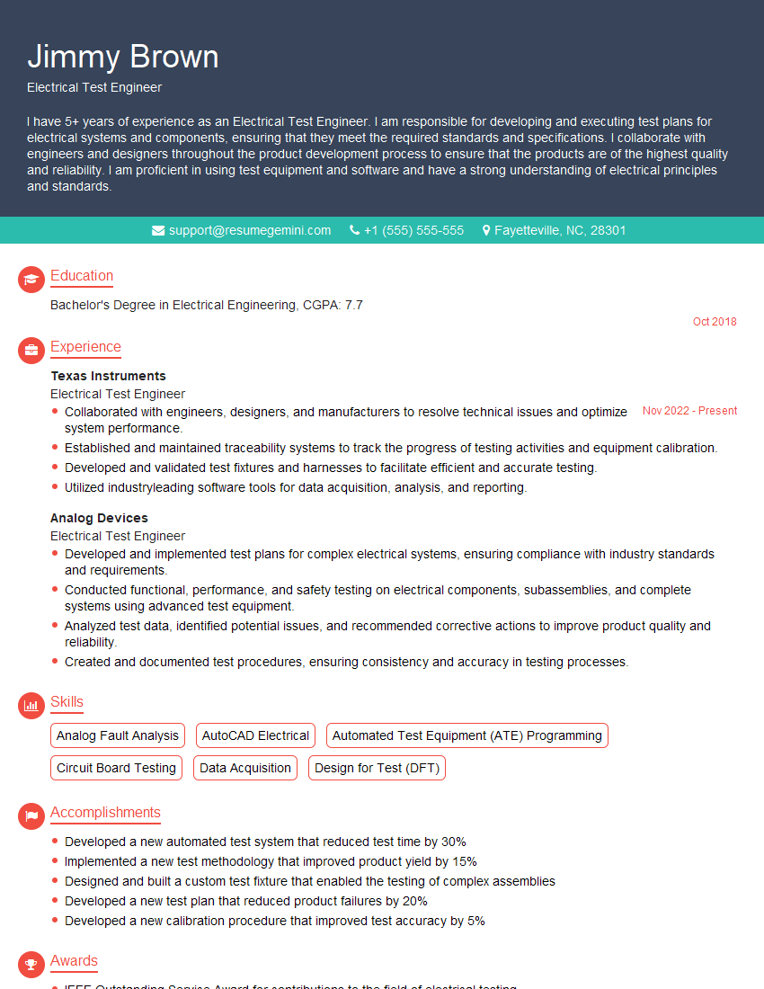
Electrical Test Engineer Resume Sample
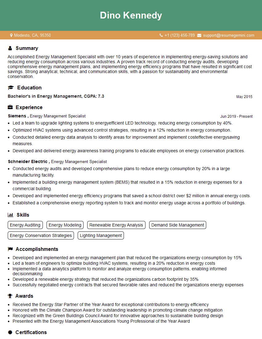
Energy Management Specialist Resume Sample
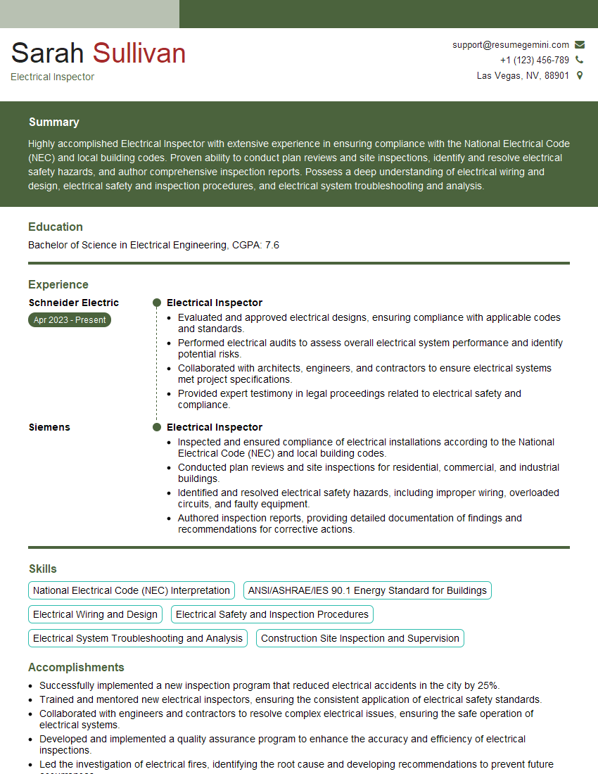
Electrical Inspector Resume Sample

Electrical Maintenance Technician Resume Sample
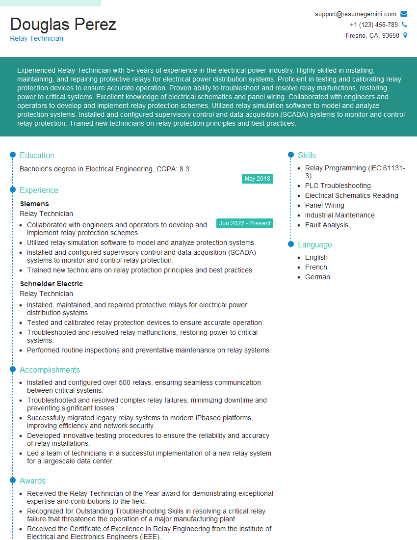
Relay Technician Resume Sample
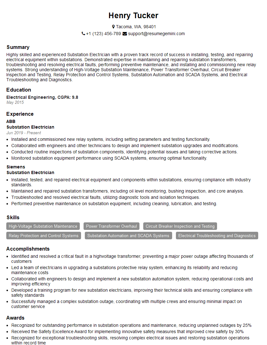
Substation Electrician Resume Sample
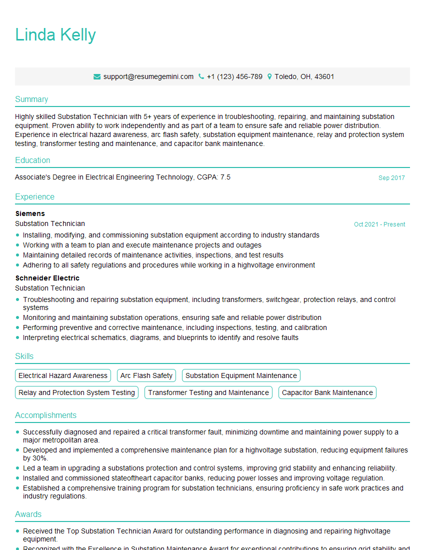
Substation Technician Resume Sample
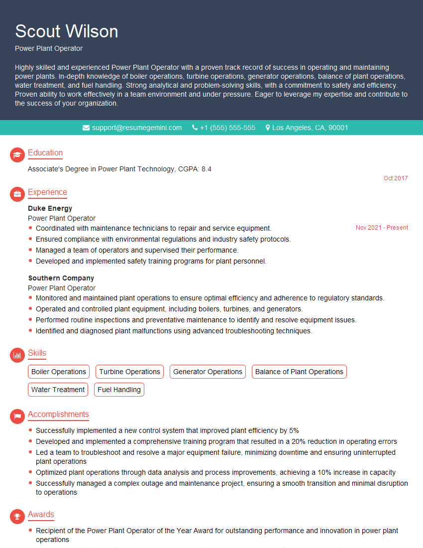
Power Plant Operator Resume Sample
Explore more articles
Users Rating of Our Blogs
Share Your Experience
We value your feedback! Please rate our content and share your thoughts (optional).
What Readers Say About Our Blog
To the interviewgemini.com Webmaster.
Very helpful and content specific questions to help prepare me for my interview!
Thank you
To the interviewgemini.com Webmaster.
This was kind of a unique content I found around the specialized skills. Very helpful questions and good detailed answers.
Very Helpful blog, thank you Interviewgemini team.