Interviews are more than just a Q&A session—they’re a chance to prove your worth. This blog dives into essential Working from blueprints and sketches to determine the exact placement of artwork interview questions and expert tips to help you align your answers with what hiring managers are looking for. Start preparing to shine!
Questions Asked in Working from blueprints and sketches to determine the exact placement of artwork Interview
Q 1. Explain the process of converting a sketch into precise artwork placement coordinates.
Converting a sketch into precise artwork placement coordinates requires a methodical approach. First, I’d carefully analyze the sketch, noting key reference points and dimensions. These could be corners, centers, or significant features within the artwork and its intended location on the blueprint. Then, I would overlay a grid system – either physically or digitally – onto the sketch and the blueprint. This grid serves as a common coordinate system allowing for precise measurement and conversion. Each grid intersection represents a unique coordinate. By referencing the grid, I can determine the X and Y coordinates of the artwork’s key points relative to the blueprint’s origin point. This data can then be used to determine the precise placement within any CAD or design software.
For example, if a sketch shows a logo needing placement 2 inches from the left edge and 3 inches from the top edge of a wall depicted on a blueprint, and my grid has 1 inch intervals, I can directly use (2,3) as its coordinates. Software can then easily place the artwork accurately.
Q 2. How do you handle discrepancies between a blueprint and a provided artwork dimension?
Discrepancies between blueprint and artwork dimensions require careful consideration. First, I’d verify the units of measurement used in both (inches, centimeters, etc.). Then, I identify the source of the discrepancy. Is it a scaling issue or a measurement error? If it’s a scaling problem, I adjust the artwork’s dimensions to match the blueprint’s scale. If it’s a measurement error, I need to decide which source is more reliable and either correct the blueprint or re-size the artwork, documenting the changes. Often, a small discrepancy (within a reasonable tolerance) can be accommodated by minor adjustments to the artwork’s placement to maintain the overall design intent. Clear communication with the design team is crucial in making these decisions.
For example, if the artwork is 5% larger than what the blueprint allows, I might either slightly reduce the artwork’s size or, if the design permits, slightly adjust its position to fit within the allocated space. I’d always document these modifications.
Q 3. Describe your experience working with different scaling ratios in blueprints.
Working with different scaling ratios in blueprints is a common task. My experience includes handling various scales, from 1:1 to 1:100 and beyond. I’m proficient in using both manual and digital methods to accurately translate artwork into the blueprint’s scale. Manually, I use precise rulers, scales, and proportional dividers. Digitally, I utilize CAD software to adjust the artwork’s dimensions based on the blueprint’s scale factor. This ensures that the final artwork placement remains consistent with the overall design, regardless of the scale.
For instance, if a blueprint has a scale of 1:50, and the artwork in the sketch is 10cm wide, then I would input this information into my CAD program; the program would automatically scale the artwork down to 0.2cm (10cm / 50) to match the blueprint’s scale before placement.
Q 4. How do you ensure accurate artwork placement when dealing with multiple layers in a blueprint?
Ensuring accurate artwork placement with multiple blueprint layers requires a layered approach to the process itself. I start by carefully analyzing the blueprint’s layers to understand the spatial relationships between elements. I typically assign each layer to a different color or visual identifier in my design software, making it easy to see the layers without cluttering the image. Then I determine the order of placement: structural elements first, followed by fixtures, and then decorative elements like the artwork. By working in this order, I minimize the risk of overlaps and conflicts. This layer-by-layer approach allows me to meticulously place the artwork within its designated area, taking into account the depth and positioning of other elements.
Think of it like painting a room: you’d paint the walls (structural layer) before adding trim (fixture layer) and finally hanging a picture (artwork layer). This structured process ensures that no part of the design is compromised.
Q 5. What software are you proficient in for interpreting blueprints and placing artwork?
I’m proficient in several software applications for blueprint interpretation and artwork placement. These include AutoCAD, Revit, SketchUp, and Adobe Illustrator. AutoCAD and Revit are excellent for working with complex architectural blueprints, allowing precise measurements and coordinate manipulation. SketchUp is useful for 3D visualization and checking for potential conflicts before final placement. Adobe Illustrator is perfect for vector-based artwork, ensuring scalability and crispness regardless of the final output size or medium. My expertise extends to using the measuring and coordinate tools in each program to ensure accurate artwork placement.
Q 6. How do you identify and resolve potential conflicts between artwork placement and other design elements in a blueprint?
Identifying and resolving conflicts between artwork placement and other design elements requires a keen eye for detail and a thorough understanding of spatial relationships. I use the software’s layering and visualization capabilities to identify potential overlaps or interferences. This often involves zooming in closely on the blueprint to examine the artwork’s intended location against existing elements. If a conflict is detected, I explore several solutions, including resizing the artwork, repositioning it to a less congested area, or modifying the surrounding design elements. The best solution depends on the context of the project and the priority given to specific design features. Prioritizing communication is key to effectively resolving conflicts.
For example, if artwork overlaps with a door, I might reduce the artwork’s size, move the artwork, or adjust the position of the door (if feasible). The chosen solution would depend on factors such as the relative importance of the artwork and the door in the overall design.
Q 7. How do you maintain precision when transferring artwork onto different materials based on blueprint specifications?
Maintaining precision when transferring artwork onto different materials requires careful consideration of the material’s properties and the chosen transfer method. For example, transferring artwork onto wood requires a different approach than transferring it onto canvas. Regardless of the material, I begin by carefully scaling the artwork to match the blueprint specifications. Then, I use appropriate tools and techniques for each material – this could include printers, projectors, or even hand-drawing, ensuring precise alignment and accurate dimensions. I always perform a test transfer on a scrap piece of the same material to avoid costly mistakes on the final product.
Using a projector for larger-scale artwork onto a wall, for instance, ensures accurate scaling and positioning by projecting a scaled image directly onto the surface. This allows me to accurately trace the artwork for the final installation, achieving high levels of accuracy.
Q 8. How would you approach scaling artwork to fit a specified area on a blueprint?
Scaling artwork to fit a blueprint requires precise calculations and attention to detail. I typically start by determining the scale of the blueprint itself – this information is usually found on the blueprint’s title block. Let’s say the blueprint’s scale is 1:50, meaning 1 unit on the blueprint represents 50 units in real life.
Next, I measure the designated area on the blueprint for the artwork. If the space measures 2 inches by 3 inches on the blueprint, at a 1:50 scale, this translates to a 100-inch by 150-inch area in reality. I then determine the dimensions of the artwork. If the artwork is 50 inches by 75 inches, it perfectly fits the scaled space. However, if the artwork is larger or smaller, I use proportional scaling to adjust its dimensions while maintaining the aspect ratio to avoid distortion. I might use software like AutoCAD or Adobe Illustrator to perform these calculations and scaling operations automatically.
For example, if the artwork is 75 inches by 100 inches, I would need to reduce its dimensions proportionally to fit the 100-inch by 150-inch space, maintaining the correct ratio. I might reduce the longer side by 100/150 = 0.667, applying the same scale factor to the shorter side, achieving the desired fit.
Q 9. Describe your process for verifying the accuracy of artwork placement before finalizing the design.
Verifying artwork placement accuracy is crucial. My process involves a multi-step approach. First, I always double-check my calculations and scaling using independent methods. I might manually measure the blueprint again and use a different scaling calculation to ensure consistency. Second, I utilize digital tools like CAD software to create a virtual representation of the artwork placed within the blueprint. This allows me to visualize the artwork in context and identify any potential discrepancies early.
Third, I perform a thorough visual inspection, comparing the placement of the artwork to other features on the blueprint. I check for any overlaps with doors, windows, or other architectural elements. Finally, I create a detailed overlay drawing, showing the artwork precisely positioned against the background of the blueprint, allowing for a clear and comprehensive visual confirmation before final approval. This approach ensures minimal room for error and maintains the integrity of the design.
Q 10. What methods do you employ to ensure consistency in artwork placement across multiple blueprints?
Maintaining consistency in artwork placement across multiple blueprints is paramount. I establish a central reference point, either a physical or digital one. This could be a key architectural feature, like a main entrance or a central axis, that serves as a consistent point of reference across all blueprints. I then use this reference point to calculate the relative position of the artwork on each blueprint, thereby ensuring uniformity.
Furthermore, I utilize a standardized digital template or a style guide that dictates the preferred methods for scaling and positioning the artwork. This ensures that all team members use the same techniques and maintain consistent artwork placement even when working on different blueprints within the same project. This methodology enhances accuracy and greatly reduces the risk of inconsistencies across different plans and revisions.
Q 11. How do you adapt your approach to artwork placement based on different blueprint styles or formats?
Different blueprint styles and formats require adaptable strategies. For instance, older blueprints might be hand-drawn and less precise, requiring meticulous manual measurements and adjustments. In contrast, digital blueprints provide greater accuracy and allow for the use of sophisticated software tools. The approach also needs to adapt to various scales. A large-scale blueprint for a building might require very different scaling calculations than a smaller-scale detail drawing.
Regardless of the format, I always prioritize understanding the blueprint’s conventions, notation, and scale before proceeding with artwork placement. I carefully study the plan to identify key architectural features and ensure that the artwork complements the design while respecting the existing structure. Flexibility and a solid understanding of architectural drawing principles are key to handling the diversity in blueprint styles and formats.
Q 12. How do you communicate artwork placement details effectively to other team members?
Effective communication of artwork placement details is crucial for seamless collaboration. I primarily use annotated digital versions of the blueprint, clearly marking the artwork’s exact dimensions, location, and any specific instructions. This might involve using layers in CAD software or employing specific notations and labels directly on the blueprint. I also utilize detailed specifications sheets that provide precise numerical coordinates and scale information to further enhance clarity.
In addition to visual aids, I engage in regular team meetings and presentations to discuss the artwork placement strategy, answering any questions and addressing any concerns. This approach ensures that everyone is informed and on the same page, contributing to better overall team understanding and efficient execution of the design.
Q 13. How do you handle revisions and updates to artwork placement based on client feedback or design changes?
Handling revisions and updates is a routine part of the design process. I maintain a detailed revision history for each blueprint, logging all changes made to the artwork placement. This allows for easy tracking of updates and ensures that the team is aware of all revisions. When changes are requested, I first carefully analyze the client’s feedback or the design modifications, then adjust the artwork placement accordingly.
I use version control in my software to manage different iterations and save backups of previous designs. This practice safeguards against accidental data loss and enables the team to revert to prior versions if needed. The revised blueprints are clearly marked with the revision number and date, maintaining a clear and organized record of the design evolution.
Q 14. Describe your experience with interpreting architectural blueprints for artwork placement.
My experience interpreting architectural blueprints for artwork placement spans several years and diverse projects. I’m proficient in reading various blueprint types, including floor plans, elevation drawings, and section views. I understand how to extract relevant information like room dimensions, wall locations, ceiling heights, and other crucial details that impact artwork placement. For instance, I would examine a floor plan to determine the available wall space for a mural, or an elevation drawing to assess the appropriate height and placement of a sculpture.
Beyond basic understanding, I can recognize and interpret various architectural symbols, notations, and specifications. This expertise allows me to anticipate potential challenges and effectively integrate artwork within the architectural design, always considering factors like sightlines, traffic flow, and structural limitations. My skills extend beyond simple placement; I actively contribute to design decisions, considering scale, proportion, and the overall aesthetic impact of the artwork in its intended space.
Q 15. Explain your understanding of different units of measurement used in blueprints and how it relates to artwork placement.
Blueprints and sketches utilize various units of measurement, primarily inches, millimeters, and centimeters. Understanding these is crucial for accurate artwork placement. Inches are common in US-based projects, while millimeters and centimeters are prevalent in international projects. Inconsistencies can lead to significant errors. For example, a 1-inch error in a large-scale mural could mean a several-inch deviation in the final product.
I always double-check the scale of the blueprint or sketch – often denoted in a title block or legend – before beginning any measurements. Then, I meticulously convert units if necessary, using a reliable conversion tool to maintain precision. I might convert all measurements to a single unit (e.g., millimeters) for consistency before beginning layout calculations to prevent compounding errors.
Consider a scenario where the blueprint uses inches, but the artwork is provided in centimeters. I’d convert all blueprint dimensions to centimeters using a conversion factor (1 inch ≈ 2.54 centimeters). Then I would meticulously overlay the artwork’s dimensions onto the converted blueprint measurements to ensure a perfect fit. This avoids costly mistakes that can arise from measurement inaccuracies.
Career Expert Tips:
- Ace those interviews! Prepare effectively by reviewing the Top 50 Most Common Interview Questions on ResumeGemini.
- Navigate your job search with confidence! Explore a wide range of Career Tips on ResumeGemini. Learn about common challenges and recommendations to overcome them.
- Craft the perfect resume! Master the Art of Resume Writing with ResumeGemini’s guide. Showcase your unique qualifications and achievements effectively.
- Don’t miss out on holiday savings! Build your dream resume with ResumeGemini’s ATS optimized templates.
Q 16. How do you account for material thickness and other physical constraints when placing artwork?
Accounting for material thickness is essential to avoid misalignment. Imagine trying to place a sticker on a door; if you don’t account for the door’s thickness, the sticker will be off. This is true for all projects, ranging from murals on walls to signage on fabricated structures. I always check the material specifications provided alongside the blueprint, which includes thickness details (e.g., wall thickness, panel depth). I then add these thicknesses to my calculations to determine the exact artwork placement point.
Similarly, physical constraints such as existing fixtures, pipes, or electrical outlets must be meticulously accounted for. I use a layered approach, digitally or physically, where I first lay out the artwork without considering constraints. Then, I overlay constraint information to adjust the artwork’s position and ensure it doesn’t overlap or interfere with existing elements. This iterative process allows for accurate placement within the boundaries of the physical environment. This might involve slightly repositioning the artwork or even adjusting the artwork itself to accommodate the constraints.
Q 17. Describe your experience with using templates or guides for consistent artwork placement.
Templates and guides are indispensable for ensuring consistent artwork placement, especially in repetitive tasks. For instance, when designing multiple identical signs for a building complex, a template ensures uniformity. I use both digital and physical templates. Digital templates are created using CAD software and offer precise control and easy modification. Physical templates, like precisely cut stencils or accurately marked boards, are useful for on-site applications, particularly when dealing with less precise sketches or where digital tools are unavailable.
For example, I recently worked on a project requiring the placement of dozens of identical logo decals on storefront windows. I created a digital template in CAD, including precise measurements and alignment points. This template was then used to guide the placement of each decal, guaranteeing identical positioning across all windows and thus, maintaining brand consistency.
Q 18. How do you troubleshoot issues related to inaccurate artwork placement?
Troubleshooting inaccurate artwork placement starts with a systematic review of my process. I first verify the accuracy of the blueprint’s measurements and scales, cross-checking with multiple sources if available. Then, I review my calculations, using a calculator or software to eliminate arithmetic errors. If the issue persists, I examine the original artwork and its digital representation to ensure consistency between the two.
Physical inspection is crucial. If the discrepancy isn’t apparent from the digital review, a site visit allows for a direct comparison between the plan and the physical space. Minor discrepancies can often be corrected on-site. However, larger errors might necessitate revising the design or adjusting the artwork itself.
Documenting each step of the process, including all calculations and decisions, is crucial for identifying the source of errors in case of misplacement. This documentation serves as an audit trail enabling me to quickly identify and rectify inaccuracies.
Q 19. What are some common challenges you face when working with blueprints and sketches, and how do you overcome them?
Common challenges include unclear or incomplete blueprints, inconsistencies in scale or units, and outdated or conflicting information. For instance, I’ve encountered blueprints with missing dimensions or unclear annotation, requiring me to make educated assumptions or seek clarification from the project team. Sometimes multiple blueprints or revisions exist, which can lead to inconsistencies and confusion.
To overcome these, I employ effective communication, seeking clarification from the architects or engineers whenever ambiguity arises. I use multiple cross-references – comparing various documents to ensure consistency and resolving conflicts. Software tools like CAD programs help overcome scaling issues and ensure accurate representation of the project.
In one instance, I encountered conflicting details between the architectural plans and the structural drawings. By carefully comparing and contrasting the two, and discussing discrepancies with the project team, we identified an error in the initial architectural drawings that could have led to significant artwork misplacement. Effective collaboration and meticulous verification prevented a costly error.
Q 20. How familiar are you with various types of drawing and annotation symbols found on blueprints?
I am very familiar with various drawing and annotation symbols on blueprints. This includes standard symbols for dimensions, materials, finishes, elevations, sections, and details, as well as project-specific symbols defined in the blueprint’s legend. My understanding extends to architectural, mechanical, electrical, and plumbing blueprints, recognizing the distinctions in symbols across these disciplines.
For example, I understand the symbols for different wall types (e.g., concrete, brick, drywall), plumbing fixtures (e.g., sinks, toilets), electrical outlets, and lighting fixtures. This knowledge enables me to accurately position artwork relative to these elements, avoiding obstructions and ensuring aesthetic harmony. A strong grasp of these symbols is crucial to prevent potential clashes with structural or functional components of the building.
Q 21. Describe your experience with creating mock-ups or prototypes to visualize artwork placement.
Creating mock-ups and prototypes is a crucial part of my process. For complex projects, I often create digital mock-ups using 3D modeling software or photo editing tools to visualize how the artwork will appear in the space. This allows for early detection of potential issues and facilitates client review and feedback before implementation.
For simpler projects, physical mock-ups might suffice. This could involve creating a scaled-down version of the artwork and positioning it within a scaled-down representation of the space. This hands-on approach helps visualize the final product and identify any potential problems in terms of scale, proportion, and aesthetic harmony. The mock-up allows for quick adjustments and refinements before moving to the final implementation, reducing costs and errors significantly.
In a recent project involving a large-scale mural for a restaurant, I created a digital mock-up using 3D modeling software to show the mural’s appearance within the restaurant’s interior. The mock-up helped the client visualize the final product, allowing them to suggest changes and approve the design before proceeding with production, preventing costly revisions later on.
Q 22. How do you ensure the correct orientation and alignment of artwork based on blueprint specifications?
Ensuring correct orientation and alignment hinges on meticulously interpreting blueprint specifications. This involves understanding the scale, the coordinate system used (e.g., Cartesian or polar), and the notation indicating artwork rotation and position. I always start by verifying the blueprint’s scale to ensure accurate measurements. Then, I carefully identify the designated location for each artwork piece, using the blueprint’s reference points and dimensions. For example, if the blueprint indicates artwork ‘A’ should be placed at coordinates (10, 5) with a 0-degree rotation, I use this information to precisely position the artwork on the final medium.
To ensure accuracy, I utilize digital tools like CAD software, where I can overlay the artwork on the digital blueprint for precise alignment. I also use a combination of rulers, protractors, and even laser measurement tools for physical blueprints to ensure accuracy and precision in aligning the artwork to the specifications.
Q 23. How do you handle complex or ambiguous instructions regarding artwork placement?
Ambiguous instructions are a common challenge. My approach involves a systematic process of clarification and verification. First, I carefully analyze the ambiguous instructions for any clues or context that might provide more information. This often involves looking at related sections of the blueprint or other design documentation. If needed, I communicate with the design team or client to clarify any unclear points. I treat any ambiguity as a potential source of error, so thorough communication and verification are crucial. For instance, if the placement of a logo is described vaguely as ‘centered,’ I would clarify the centering point—is it centered on the page, a specific element on the page, or within a designated frame?
Once clarification is obtained, I document the interpretation to ensure everyone is on the same page. This reduces the risk of misinterpretations later in the process. I also create multiple iterations or mock-ups with different interpretations of ambiguous instructions, presenting them for approval before proceeding.
Q 24. Explain your understanding of orthographic projections and how it impacts your artwork placement process.
Orthographic projections are fundamental to my work. They’re a way of representing a three-dimensional object on a two-dimensional plane using multiple views (typically top, front, and side). Understanding orthographic projections is crucial because blueprints often use this method to depict artwork placement in relation to the overall structure. For example, a blueprint might show the placement of a mural on a building’s exterior using a side elevation view, indicating its height and width relative to other architectural features.
I use this information to accurately position the artwork on the final medium. If there are multiple orthographic views showing the same artwork from different perspectives, I’ll cross-reference them to ensure consistency and avoid misalignment. For instance, discrepancies between the front and side elevations might highlight an error in the blueprint which I would then clarify.
Q 25. What is your approach to verifying the final artwork placement matches the design intent?
Verifying final artwork placement is a multi-step process emphasizing accuracy. I always begin with a visual inspection, comparing the final artwork placement to the blueprint. This involves meticulously checking for accurate dimensions, angles, and alignment relative to other elements. I use precise measuring tools to double-check numerical values for a margin of error less than 1mm. If the scale of the blueprint is very small, I might use a magnification tool for finer details.
Beyond visual checks, I often create a digital overlay of the artwork on a digital version of the blueprint, enabling a precise comparison using CAD software to ensure perfect alignment. This is especially important for complex or intricate designs. Finally, I document the verification process and any discrepancies found, capturing them in a report for the project’s record.
Q 26. Describe a time you had to correct an error in artwork placement. What was the process?
In one project, a large-scale mural was misaligned due to an incorrect interpretation of the blueprint’s scale. The blueprint used an unconventional scale, which I initially overlooked. This resulted in the mural being placed several inches off the marked position. The process of correction involved:
- Identifying the error: A careful review of the blueprint highlighted the scale issue.
- Recalculating the position: Using the correct scale, I recalculated the exact position of the mural.
- Communicating the error: I immediately communicated the error and proposed solution to the design team and client.
- Implementing the correction: With approval, we carefully repositioned the mural, ensuring it perfectly matched the revised calculations.
- Verifying the correction: We performed a thorough verification process to ensure the mural was accurately placed.
This experience underscored the importance of meticulous attention to detail and clear communication throughout the process.
Q 27. How do you manage your time effectively when working on multiple artwork placement tasks simultaneously?
Managing multiple tasks effectively relies on prioritization and organization. I use project management techniques like creating a detailed schedule that breaks down each artwork placement task into smaller, manageable steps. I also prioritize tasks based on deadlines and urgency. For example, I might tackle the most time-sensitive projects first while allocating time blocks for other projects.
I utilize digital tools such as project management software to track progress, deadlines, and dependencies between different projects. This allows for a clear overview and helps manage time efficiently. Regular review of the schedule and adaptation according to circumstances are also crucial. This allows me to identify potential bottlenecks early on and adjust accordingly. Visual aids such as Kanban boards can also be effective for managing multiple tasks visually.
Q 28. Describe your experience using CAD software for precise artwork placement
CAD software is invaluable for precise artwork placement. My experience spans various CAD programs, including AutoCAD and Revit. I leverage CAD’s capabilities for precise measurements, precise scaling, and layering capabilities to seamlessly integrate artwork into blueprints. I use digital versions of the artwork and overlay them onto the digital blueprints. This allows for precise positioning and alignment using CAD’s built-in tools like snap-to-grid and alignment functions.
Moreover, CAD allows for creating multiple iterations without affecting the original blueprint. I can easily experiment with different positions and orientations before finalizing the placement. The ability to easily create scaled drawings, detailed views, and export the designs in various formats is a great asset, streamlining communication and ensuring accuracy throughout the process.
Key Topics to Learn for Working from blueprints and sketches to determine the exact placement of artwork Interview
- Blueprint Interpretation: Understanding architectural drawings, scales, and notations to accurately translate them into artwork placement.
- Sketch Comprehension: Analyzing hand-drawn sketches, identifying key elements, and understanding the artist’s intent for artwork positioning.
- Measurement and Calculation: Accurately measuring and calculating distances, angles, and proportions to ensure precise artwork placement.
- Software Proficiency: Demonstrating familiarity with relevant design software (e.g., AutoCAD, Adobe Illustrator) for digital placement and manipulation of artwork.
- Material Considerations: Understanding the impact of different materials (e.g., canvas size, wall texture) on artwork placement and overall aesthetic.
- Problem-Solving: Addressing discrepancies between blueprints/sketches and available space, proposing creative solutions while adhering to design specifications.
- Communication & Collaboration: Effectively communicating with designers, architects, and other stakeholders to clarify placement details and resolve any conflicts.
- Workflow Optimization: Describing efficient processes for integrating artwork placement into the overall project timeline and workflow.
Next Steps
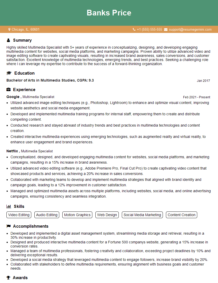
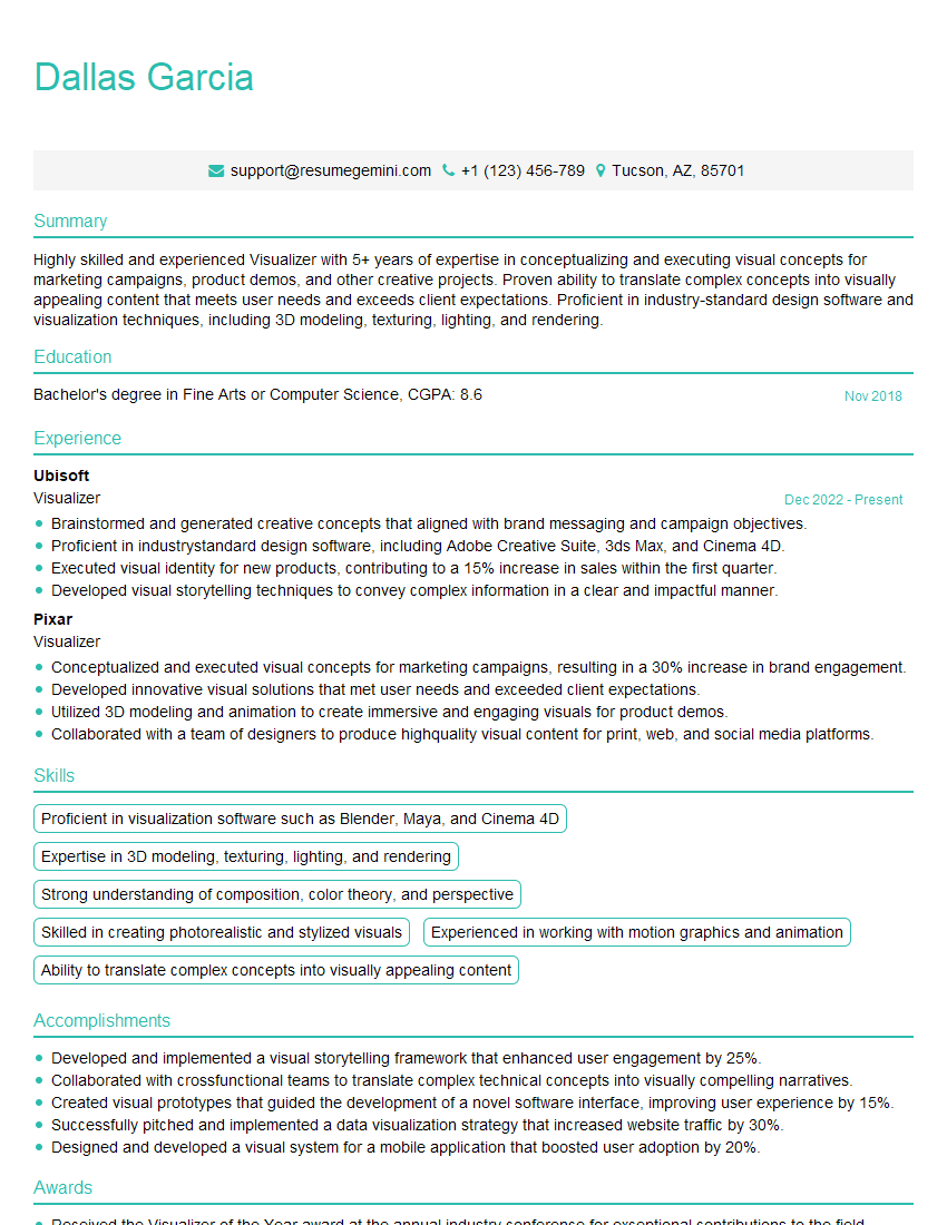
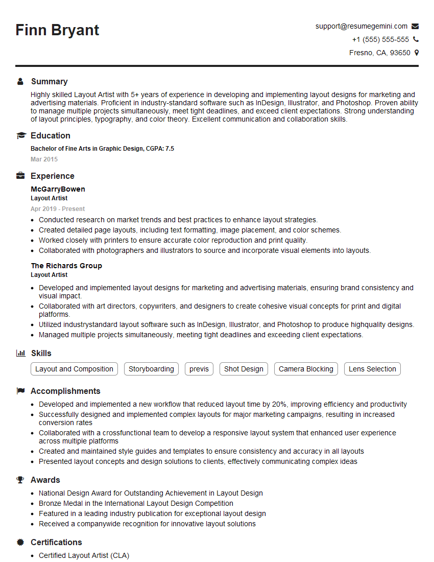
Mastering the ability to accurately place artwork based on blueprints and sketches is crucial for career advancement in design and related fields. It demonstrates attention to detail, problem-solving skills, and a strong understanding of spatial relationships – all highly valued attributes. To significantly enhance your job prospects, focus on crafting a resume that’s optimized for Applicant Tracking Systems (ATS). ResumeGemini can help you build a professional, ATS-friendly resume that highlights your skills and experience effectively. Examples of resumes tailored to this specific skill set are available to guide you through the process.




Explore more articles
Users Rating of Our Blogs
Share Your Experience
We value your feedback! Please rate our content and share your thoughts (optional).
What Readers Say About Our Blog
To the interviewgemini.com Webmaster.
Very helpful and content specific questions to help prepare me for my interview!
Thank you
To the interviewgemini.com Webmaster.
This was kind of a unique content I found around the specialized skills. Very helpful questions and good detailed answers.
Very Helpful blog, thank you Interviewgemini team.