The right preparation can turn an interview into an opportunity to showcase your expertise. This guide to Knowledge of Instrumentation and Control interview questions is your ultimate resource, providing key insights and tips to help you ace your responses and stand out as a top candidate.
Questions Asked in Knowledge of Instrumentation and Control Interview
Q 1. Explain the difference between open-loop and closed-loop control systems.
The core difference between open-loop and closed-loop control systems lies in their feedback mechanisms. An open-loop system, also known as a feedforward system, simply executes a pre-determined action without considering the actual output. Think of a toaster: you set the time, and it toasts for that duration regardless of whether the bread is perfectly browned. The output is not monitored or used to adjust the input.
In contrast, a closed-loop system, or feedback control system, continuously monitors the output and compares it to the desired setpoint. Any discrepancy between the two triggers a correction in the input to reduce the error. Imagine a cruise control system in a car: it constantly monitors the vehicle’s speed and adjusts the throttle to maintain the set speed, compensating for inclines or headwinds. This feedback loop ensures the system stays closer to the desired outcome.
Example: A simple water pump controlled by a timer is an open-loop system. The pump runs for a set time, regardless of the water level in the tank. A water pump with a level sensor that adjusts the pump based on the water level is a closed-loop system.
Q 2. Describe the function of a PID controller and its tuning parameters.
A PID controller is a widely used feedback controller that adjusts the input to a system based on three factors: Proportional, Integral, and Derivative actions. It aims to minimize the error between the desired setpoint and the actual output.
- Proportional (P) action: This action is proportional to the current error. A larger error results in a larger corrective action. It’s immediate but often leaves a persistent offset (steady-state error).
- Integral (I) action: This action addresses the steady-state error by accumulating the error over time. It ensures the output eventually reaches the setpoint, eliminating the offset. However, it can lead to overshoot and oscillations if not carefully tuned.
- Derivative (D) action: This action anticipates future error by considering the rate of change of the error. It helps to dampen oscillations and speed up response time, preventing overshoot.
Tuning parameters, typically Kp (proportional gain), Ki (integral gain), and Kd (derivative gain), determine the contribution of each action. Finding the optimal values often involves trial-and-error or using advanced tuning methods like Ziegler-Nichols. Incorrect tuning can lead to instability (oscillations), sluggish response, or large overshoots. Imagine tuning a car’s suspension – too stiff (high Kp) and it’s bumpy, too soft (low Kp) and it’s unresponsive.
Q 3. What are the different types of sensors used in industrial instrumentation?
Industrial instrumentation utilizes a vast array of sensors to measure various process variables. Some common types include:
- Temperature Sensors: Thermocouples, RTDs (Resistance Temperature Detectors), thermistors, infrared sensors.
- Pressure Sensors: Strain gauge pressure transmitters, capacitive pressure sensors, piezoelectric pressure sensors.
- Flow Sensors: Orifice plates, venturi tubes, rotameters, ultrasonic flow meters, magnetic flow meters.
- Level Sensors: Float switches, ultrasonic level sensors, radar level sensors, capacitive level sensors.
- pH Sensors: Electrochemical sensors that measure the acidity or alkalinity of a solution.
- Gas Sensors: Sensors that detect specific gases or gas concentrations (e.g., oxygen, carbon monoxide).
- Analytical Sensors: More sophisticated sensors used for detailed chemical analysis (e.g., chromatography, spectroscopy).
The choice of sensor depends on factors like the application, accuracy required, process conditions (temperature, pressure), and cost.
Q 4. Explain the principle of operation of a pressure transmitter.
A pressure transmitter converts pressure into a standardized electrical signal (e.g., 4-20 mA). Many utilize a strain gauge as the sensing element. A strain gauge is a tiny resistor whose resistance changes proportionally to the amount of strain (deformation) it experiences. The pressure applied to a diaphragm or other flexible element causes a change in the diaphragm’s shape, straining the attached strain gauge(s). This resistance change is measured using a Wheatstone bridge circuit, converting it into an electrical signal that represents the pressure.
Example: In a chemical process, a pressure transmitter might monitor the pressure inside a reactor vessel to ensure safe operating conditions. If pressure exceeds a set limit, the transmitter signals a control system to take corrective action, such as venting excess pressure.
Q 5. How does a flow meter work?
Flow meters measure the volumetric or mass flow rate of a fluid (liquid or gas). Different types operate on diverse principles:
- Differential Pressure Flow Meters (Orifice Plates, Venturi Tubes): These create a pressure drop across a restriction, and the flow rate is calculated based on this pressure difference using Bernoulli’s equation.
- Positive Displacement Flow Meters: These mechanically measure the volume of fluid passing through a chamber. Examples include rotary vane meters and piston meters.
- Ultrasonic Flow Meters: These use sound waves to measure the velocity of the fluid. The time it takes for sound to travel upstream and downstream is compared to determine the flow rate.
- Magnetic Flow Meters: These measure the voltage induced in a conductive fluid as it flows through a magnetic field (Faraday’s law). This is suitable for conductive fluids only.
- Turbine Flow Meters: A turbine spins proportionally to the flow rate, and the rotational speed is measured.
The choice of flow meter depends on factors like fluid properties (viscosity, conductivity), flow rate range, accuracy requirements, and cost. For instance, an ultrasonic flowmeter is suitable for non-conductive fluids, whereas a magnetic flowmeter is preferred for conductive fluids.
Q 6. Describe different types of valves used in process control.
Valves are essential components in process control, controlling the flow of fluids. Different types offer unique features:
- Globe Valves: Commonly used for on/off control or throttling. They offer good controllability but can be prone to cavitation.
- Ball Valves: Simple on/off valves with a rotating ball to block or allow flow. Fast and reliable, good for high pressure applications.
- Butterfly Valves: Similar to ball valves but use a rotating disc to control flow. Suitable for large diameter pipes but offer less precise control than globe valves.
- Control Valves: These are designed for precise control of flow, usually using pneumatic or electric actuators to adjust a valve positioner. Examples include pneumatic diaphragm valves and electric motor-operated valves.
- Check Valves: Prevent backflow of fluids. They open automatically in one direction and close when flow reverses.
The selection of a valve depends on the process requirements, including pressure, temperature, fluid properties, and the level of control needed. A control valve is essential for precise process control, while a simple ball valve may suffice for on/off operations.
Q 7. What is SCADA and its role in industrial automation?
SCADA (Supervisory Control and Data Acquisition) is a system used to monitor and control industrial processes remotely. It combines hardware and software to gather data from various field devices (sensors, actuators, PLCs), process this data, and provide operators with a centralized view of the entire process.
Role in industrial automation: SCADA plays a critical role by:
- Monitoring: Providing real-time data visualization of process variables (temperature, pressure, flow, level).
- Control: Enabling operators to remotely control process parameters through human-machine interfaces (HMIs).
- Data Logging and Reporting: Recording process data for analysis, trend identification, and reporting purposes.
- Alarm Management: Triggering alarms based on pre-defined thresholds and conditions, alerting operators to potential problems.
- Remote Diagnostics: Facilitating troubleshooting and remote maintenance of equipment.
SCADA systems are widely used in various industries, including power generation, water treatment, oil and gas, manufacturing, and transportation. They improve efficiency, enhance safety, and facilitate optimal process control.
Q 8. Explain the concept of data acquisition and its importance in process control.
Data acquisition (DAQ) is the process of sampling signals from the real world and converting them into digital data that a computer can understand and process. Think of it like taking the temperature of a reactor – the thermometer is your sensor, and the DAQ system reads that temperature and sends it to a control system. In process control, DAQ is crucial because it provides the necessary feedback for automated control loops. Without knowing the current state of the process (temperature, pressure, flow rate, etc.), a control system cannot effectively maintain the desired setpoints.
For example, in a chemical plant, sensors continuously monitor parameters like temperature and pressure. The DAQ system collects this raw data, filters out noise, and converts it to a usable format for the control system. This information is used to make adjustments and maintain optimal operating conditions. Without reliable DAQ, there’s a risk of inefficient operations, product quality issues, safety hazards, and costly downtime.
In essence, DAQ acts as the bridge between the physical process and the digital control system, enabling intelligent automation and optimization.
Q 9. What are the different communication protocols used in industrial automation?
Industrial automation utilizes a variety of communication protocols, each with its own strengths and weaknesses. The choice depends on factors such as speed, distance, data volume, and cost. Some common protocols include:
- Profibus: A widely used fieldbus protocol known for its robustness and speed in industrial environments. It’s ideal for deterministic real-time control applications.
- Profinet: An Ethernet-based industrial networking standard offering high bandwidth and scalability. Its flexibility makes it suitable for a broader range of applications, including data acquisition and complex control systems.
- Modbus: A simple and widely adopted serial communication protocol used for various industrial devices. It’s often preferred for its simplicity and ease of implementation, especially in smaller systems.
- Ethernet/IP: An industrial Ethernet protocol developed by Rockwell Automation, offering high speed and flexibility for complex automation systems. Commonly used in larger scale installations.
- ControlNet: A high-speed, real-time Ethernet-based protocol used for demanding control applications where very quick responses are necessary.
These protocols allow various devices, including PLCs, sensors, actuators, and HMI systems, to seamlessly communicate and exchange data. Imagine a modern manufacturing plant – many different machines and processes need to talk to each other for efficient operations. These communication protocols enable that efficient exchange of information.
Q 10. Describe your experience with PLC programming (e.g., ladder logic).
I have extensive experience in PLC programming, primarily using ladder logic. Ladder logic’s visual nature makes it intuitive for designing and troubleshooting control systems. I’ve worked with various PLC platforms, including Allen-Bradley and Siemens, and am proficient in designing programs for a variety of applications such as sequential control, process control, and motion control. For example, in one project, I developed a ladder logic program to control a complex packaging line, ensuring precise timing and coordination between multiple conveyors, sensors, and actuators. This involved implementing timers, counters, and various logic functions to ensure efficient and error-free operation. Another project involved designing a PLC program for a temperature control system using PID (Proportional-Integral-Derivative) control algorithms within the ladder logic, which required a deep understanding of process control principles and tuning techniques to maintain precise temperature setpoints.
I am also comfortable with structured text and function block programming, extending my capabilities beyond basic ladder logic. This allows me to create more modular, reusable, and maintainable code for complex projects.
Q 11. Explain your experience with DCS systems.
My experience with Distributed Control Systems (DCS) involves working with various platforms, including Honeywell Experion and Emerson DeltaV. DCS systems are critical for large-scale processes requiring redundancy, high availability, and advanced control strategies. I have been involved in projects ranging from system configuration and design to programming, troubleshooting, and maintenance. This includes developing control strategies, configuring alarm and safety systems, and integrating third-party devices into the overall DCS architecture. For instance, I was involved in a project where we upgraded the DCS system of a large refinery. This required careful planning, testing, and validation to ensure seamless transition and minimal downtime. The upgrade involved implementing advanced control algorithms for improved efficiency and product quality while enhancing safety features. I also have experience utilizing DCS historian systems for data analysis and process optimization.
Q 12. How do you troubleshoot instrumentation and control problems?
Troubleshooting instrumentation and control problems requires a systematic and methodical approach. My troubleshooting strategy typically involves the following steps:
- Gather Information: Begin by collecting data such as alarm logs, historical trends, and operator observations. What symptoms are occurring? When did they start?
- Isolate the Problem: Use a combination of logic and testing to narrow down the potential causes. This might involve checking wiring, testing sensors and actuators, and reviewing control logic.
- Test and Verify: Once a likely cause is identified, test it thoroughly. This could involve simulating conditions or replacing suspect components.
- Implement Corrective Action: Once the root cause is identified and verified, implement the appropriate corrective action, whether it’s repairing a faulty sensor, adjusting control parameters, or replacing a damaged component.
- Document Findings: Finally, thoroughly document the problem, the troubleshooting process, and the corrective action taken. This will aid future troubleshooting efforts and help prevent similar problems from recurring.
For example, if a temperature loop is out of control, I might first check the temperature sensor for accuracy and proper calibration. If that’s fine, I’d then check the associated valves, wiring, and finally the control logic itself within the PLC or DCS system.
Q 13. What is calibration and why is it important?
Calibration is the process of comparing the output of an instrument to a known standard to determine its accuracy. It’s akin to making sure your kitchen scale accurately measures ingredients. In the context of instrumentation and control, accurate measurements are critical for reliable operation and safety. If an instrument is not properly calibrated, it can lead to inaccurate readings, resulting in incorrect control actions, suboptimal process performance, quality issues, and even safety hazards. For example, an incorrectly calibrated pressure sensor in a pipeline could lead to an overpressure situation. Calibration ensures instruments provide accurate and reliable data for control loops and decision-making.
Calibration is typically performed at regular intervals according to manufacturer recommendations and regulatory requirements. The frequency depends on the criticality of the measurement, environmental conditions, and instrument wear and tear.
Q 14. Describe your experience with instrumentation loop diagrams.
Instrumentation loop diagrams (ILDs) are schematic representations of an instrument control loop, showing the flow of signals and components from the sensor to the final control element. They are essential for understanding the relationship between different components in a system. I have significant experience in reviewing, interpreting, and creating ILDs. They are crucial for troubleshooting, design, maintenance, and documentation purposes. An ILD clearly illustrates the instrumentation tags, signal types (analog, digital), wiring connections, and control logic. Having a well-documented ILD simplifies maintenance tasks, accelerates problem resolution, and supports efficient modifications to existing systems. For example, when dealing with a malfunction in a pressure control loop, referring to the ILD immediately provides a visual reference for identifying all components involved and facilitating efficient troubleshooting.
Q 15. What safety measures are essential when working with instrumentation and control systems?
Safety is paramount in instrumentation and control systems. A single malfunction can have catastrophic consequences. Essential safety measures include:
- Lockout/Tagout (LOTO): Before any work on equipment, power and energy sources must be isolated and locked out to prevent accidental activation. This is crucial for preventing injuries from unexpected starts or releases of hazardous materials.
- Permit-to-Work Systems: Formal procedures that authorize specific tasks after a risk assessment, ensuring workers have the proper training, equipment, and safety measures in place.
- Personal Protective Equipment (PPE): Appropriate PPE such as safety glasses, gloves, and flame-resistant clothing must be worn at all times, depending on the hazards involved. This is essential to protect against chemical splashes, electrical shocks, and other potential dangers.
- Regular Inspections and Maintenance: Preventative maintenance minimizes the risk of equipment failure. Regular calibration of instruments also ensures accurate readings, preventing control errors that may lead to accidents.
- Emergency Shutdown Systems (ESD): These systems automatically shut down processes in case of dangerous conditions, preventing escalation of incidents.
- Emergency Response Plan: A well-defined emergency plan should outline procedures for handling various types of incidents, including emergency shutdowns, evacuations, and first aid.
- Proper Training and Competency: All personnel working with instrumentation and control systems must be adequately trained and understand the associated risks and safety procedures. This includes training on lockout/tagout procedures, emergency response, and safe work practices.
For example, in a chemical plant, LOTO procedures would be strictly followed before accessing a valve on a high-pressure pipeline containing hazardous chemicals. Failure to do so could result in a serious accident.
Career Expert Tips:
- Ace those interviews! Prepare effectively by reviewing the Top 50 Most Common Interview Questions on ResumeGemini.
- Navigate your job search with confidence! Explore a wide range of Career Tips on ResumeGemini. Learn about common challenges and recommendations to overcome them.
- Craft the perfect resume! Master the Art of Resume Writing with ResumeGemini’s guide. Showcase your unique qualifications and achievements effectively.
- Don’t miss out on holiday savings! Build your dream resume with ResumeGemini’s ATS optimized templates.
Q 16. Explain the concept of process control loops and their components.
A process control loop is a closed-loop system designed to maintain a process variable at a desired setpoint. Think of it like a thermostat controlling room temperature. Its core components are:
- Process Variable (PV): The measured quantity we want to control, such as temperature, pressure, flow rate, or level. For instance, the temperature of a reactor in a chemical plant.
- Sensor/Transmitter: Measures the PV and converts it into a signal that can be understood by the controller (e.g., a temperature sensor sending a 4-20 mA signal). Imagine this as a thermometer reporting the temperature.
- Controller: Compares the PV to the desired setpoint (SP) and calculates the necessary correction signal to reduce the error between PV and SP. This is like the brain of the system making decisions.
- Actuator: Receives the signal from the controller and adjusts the manipulated variable (MV) to bring the PV closer to the SP. For example, this could be a valve adjusting the flow of coolant.
- Final Control Element (FCE): This is usually a control valve, but it could also be a motor or another device that physically adjusts the process. This actually does the work of changing the process condition.
These components form a feedback loop: the controller continuously monitors the PV, compares it to the SP, and adjusts the MV accordingly. This continues until the PV is stable at the SP. For instance, if the temperature of a reactor falls below the setpoint, the controller will open a steam valve (actuator) to increase the heat input, bringing the temperature back up.
Q 17. How do you handle process upsets and deviations from setpoints?
Process upsets and deviations from setpoints are common occurrences. Handling them requires a systematic approach:
- Identify the Cause: The first step is to determine why the process deviated from the setpoint. Is it due to a sensor malfunction, a change in feedstock properties, or a problem with the control loop itself?
- Implement Corrective Actions: Once the cause is identified, appropriate corrective actions can be implemented. This could involve adjusting the controller tuning parameters, repairing faulty equipment, or making changes to the process itself.
- Monitor the Process: Closely monitor the process to ensure the corrective actions are effective and the process is returning to the setpoint. This includes reviewing trends, alarm logs, and other relevant data.
- Investigate and Prevent Future Occurrences: After resolving the immediate issue, analyze the event to identify underlying causes and implement preventative measures to reduce the likelihood of similar upsets in the future. This could involve process improvements, better instrumentation, or enhanced operator training.
For example, if a reactor temperature unexpectedly rises, I would first check the temperature sensor and its readings. If the sensor is functioning correctly, I would investigate the heating system and look for possible reasons for the increased temperature. Depending on my findings, I could adjust the controller parameters or investigate equipment malfunctions.
Q 18. What is your experience with different types of control valves (e.g., globe, ball, butterfly)?
I have extensive experience with various control valve types. Each has its strengths and weaknesses:
- Globe Valves: Excellent for throttling and precise control, especially in applications requiring a wide range of flow rates. However, they can be more prone to cavitation and noise at high flow velocities.
- Ball Valves: Ideal for on/off service due to their quick opening and closing action. Less suitable for precise flow control. They are often used in applications where tight shut-off is crucial.
- Butterfly Valves: Simple and cost-effective for large diameter pipelines. Suitable for applications requiring quick on/off control but typically less precise for throttling applications. They are good for relatively large flows where precise control is not critical.
The selection depends on the application’s specific requirements. For precise control of a small flow, a globe valve would be preferred; for a large pipeline with simple on/off control, a butterfly valve might be more appropriate.
Q 19. Describe your experience with different types of actuators (e.g., pneumatic, electric, hydraulic)?
My experience encompasses various actuator types:
- Pneumatic Actuators: Reliable and suitable for hazardous areas due to their inherent safety features. However, they require compressed air and can be slower than electric actuators.
- Electric Actuators: Offer precise control, faster response times, and easy integration with control systems. They are more susceptible to electrical failures and may not be suitable for all hazardous areas.
- Hydraulic Actuators: Provide high force and speed, making them ideal for large valves or difficult applications. However, they are complex, require specialized maintenance, and present a higher risk of leakage.
The choice depends on factors such as the required force, speed, safety considerations, and the overall control system design. For instance, a large pipeline valve might use a hydraulic actuator for its high force output, while a small control valve in a clean environment might employ an electric actuator for its precision.
Q 20. Explain the concept of control valve sizing and selection.
Control valve sizing and selection is crucial for effective process control. It involves determining the valve’s size and type to ensure adequate flow capacity and controllability. This process typically involves:
- Determining Process Requirements: This involves identifying the fluid properties (viscosity, density, etc.), flow rate, pressure drop, and required control characteristics (e.g., quick opening or precise throttling).
- Selecting Valve Type: The choice depends on the process requirements. For example, a globe valve is typically used for precise control of smaller flows, while a butterfly valve may be better for larger flows requiring on/off or coarse control.
- Calculating Valve Size: The valve’s size (Cv, or flow coefficient) is calculated based on the process requirements and the manufacturer’s data. This ensures the valve can handle the required flow rate without excessive pressure drop or noise.
- Actuator Sizing: The actuator must be sized to provide enough force to fully open and close the valve against the prevailing pressures. The actuator size is selected based on the valve size and the expected operating pressure and flow.
- Valve Material Selection: The valve body and trim materials must be compatible with the process fluid and environmental conditions.
Software tools and manufacturers’ catalogs are used to assist in the selection process, ensuring the chosen valve meets the specific application requirements and operates within its design limits.
Q 21. What is your experience with instrumentation maintenance and calibration procedures?
Instrumentation maintenance and calibration are critical for ensuring the accuracy and reliability of process control systems. My experience includes:
- Preventative Maintenance: Regular inspections and cleaning to prevent equipment failure and ensure optimal performance. This includes checking for leaks, corrosion, and wear and tear.
- Calibration Procedures: Using calibrated standards and procedures to verify the accuracy of instruments (e.g., temperature transmitters, pressure gauges, flow meters). Calibration ensures the measured data is accurate, crucial for control loop stability.
- Troubleshooting and Repair: Identifying and repairing faulty instruments, restoring them to their operational state.
- Documentation: Maintaining detailed records of all maintenance and calibration activities, including dates, results, and any corrective actions taken. This is vital for auditing and compliance with regulations.
- Loop Testing: Performing functional tests and simulations to ensure the control loop performs correctly after maintenance and calibration activities.
For example, I’ve calibrated temperature transmitters using a traceable temperature bath to ensure accurate temperature readings in a reactor, preventing control errors and potential safety issues. Following standard operating procedures and maintaining detailed records are always critical.
Q 22. Describe your experience with HAZOP studies or similar risk assessments.
HAZOP (Hazard and Operability) studies are a systematic technique for identifying potential hazards and operability problems in process plants. I’ve been involved in numerous HAZOPs throughout my career, participating as both a team member and a facilitator. My experience spans various industries, including chemical processing, pharmaceuticals, and oil and gas. A typical HAZOP involves a multidisciplinary team systematically reviewing the process flow diagram (PFD) and process description, considering deviations from the intended operating parameters. We use guide words, such as ‘more,’ ‘less,’ ‘no,’ ‘part of,’ ‘reverse,’ and ‘other,’ to brainstorm potential hazards associated with each deviation. For example, in a reactor system, we might consider ‘more’ temperature, leading to potential runaway reactions and pressure relief system activation. Each identified hazard is then evaluated for its severity, likelihood, and detectability, leading to the development of appropriate safeguards or mitigation strategies. I’m proficient in documenting findings, preparing HAZOP reports, and actively participating in implementing the recommended safety measures. I’ve also worked with similar risk assessment methodologies like What-If analysis and Fault Tree Analysis (FTA), each offering slightly different approaches but with the common goal of proactively identifying and mitigating potential risks.
Q 23. What are your strengths and weaknesses in the context of instrumentation and control engineering?
My strengths lie in my strong analytical and problem-solving skills, coupled with a deep understanding of control system design and implementation. I excel at troubleshooting complex instrumentation issues and possess a solid grasp of various control algorithms, including PID control, advanced process control (APC), and model predictive control (MPC). I also possess excellent communication and teamwork skills, crucial for collaboration in multidisciplinary projects. I’m proficient in using various software tools for instrumentation and control system design and simulation. My weakness, if I had to pinpoint one, would be my occasional tendency to dive deeply into technical details, which can sometimes overshadow the broader project objectives. I’m actively working on improving this by consistently focusing on the big picture and prioritizing tasks effectively. I find that working with strong project managers helps keep me on track.
Q 24. Explain your experience with any specific software related to instrumentation and control (e.g., AspenTech, Emerson DeltaV).
I have extensive experience with Emerson DeltaV, a widely used distributed control system (DCS) in the process industry. I’ve used DeltaV for everything from initial system design and configuration to commissioning and troubleshooting. My experience includes designing control loops, configuring alarm management systems, creating operator interface screens (HMI), and managing historical data. For instance, I was involved in a project where we migrated from an older DCS to DeltaV, which required careful planning and execution to ensure seamless system transition without any process disruption. This involved extensive configuration and testing, data migration, and operator training. I also have some experience with AspenTech’s process simulation software, primarily using it for model development and process optimization studies. This experience helped to enhance the efficiency of our control strategies and optimize the entire process, leading to better performance and cost savings. I’m always eager to learn and adapt to new software, recognizing that staying current with industry standards is vital.
Q 25. Describe a challenging project you worked on related to instrumentation and control, and how you overcame the challenges.
One particularly challenging project involved the integration of a new control system into an existing, aging chemical plant. The existing system was highly customized and poorly documented, posing a significant obstacle to integration. We faced challenges with hardware compatibility, software conflicts, and the need to maintain continuous plant operation during the upgrade. To overcome these challenges, we implemented a phased approach, carefully planning the migration of individual control loops to minimize disruption. We created detailed simulation models to test the new control system before deployment and developed comprehensive testing procedures to ensure smooth transition. We also collaborated closely with plant operators to provide training and support throughout the process. This phased approach, coupled with rigorous testing and strong collaboration, allowed us to complete the integration successfully, significantly improving the plant’s efficiency and reliability. The project highlighted the importance of meticulous planning, robust testing, and effective communication in managing complex control system upgrades.
Q 26. How do you stay up-to-date with the latest advancements in instrumentation and control technology?
Staying updated in the rapidly evolving field of instrumentation and control requires a multi-pronged approach. I regularly attend industry conferences and webinars, such as those hosted by ISA (International Society of Automation) and other relevant professional organizations. I actively participate in online forums and communities, engaging in discussions and learning from peers and experts. I subscribe to leading industry journals and publications to keep abreast of the latest technological developments. Furthermore, I maintain a strong network of colleagues and mentors in the field, sharing knowledge and insights to enhance mutual learning. Finally, I embrace continuous learning by pursuing relevant online courses and training programs to maintain my skills in specific technologies and methodologies.
Q 27. What are your salary expectations?
My salary expectations are commensurate with my experience and skills, and aligned with the industry standards for a senior instrumentation and control engineer with my background. I am open to discussing this further based on the specifics of the role and the company’s compensation structure.
Q 28. Do you have any questions for me?
I have a few questions. First, could you elaborate on the specific technologies and tools used within your company? Secondly, what are the typical career progression opportunities within the company? Finally, what are the company’s current priorities and challenges in the area of instrumentation and control?
Key Topics to Learn for Knowledge of Instrumentation and Control Interview
- Process Instrumentation: Understanding various types of sensors (temperature, pressure, flow, level), their principles of operation, selection criteria, and limitations. Consider practical applications like choosing the right sensor for a specific process variable in a chemical plant.
- Control Systems: Mastering feedback control loops (PID controllers), their tuning methods, and the impact of different control strategies on process stability and performance. Explore case studies on optimizing control loops for improved efficiency.
- Data Acquisition and SCADA Systems: Familiarize yourself with data acquisition techniques, Supervisory Control and Data Acquisition (SCADA) systems, and their role in monitoring and controlling industrial processes. Think about the challenges of integrating diverse data sources and ensuring data integrity.
- Process Safety and Instrumentation: Understand safety instrumented systems (SIS), their design principles, and their critical role in preventing hazardous events. Consider examples of safety interlocks and emergency shutdown systems.
- Calibration and Maintenance: Learn about the importance of instrument calibration, preventative maintenance procedures, and troubleshooting techniques. Discuss real-world scenarios where improper calibration led to process upsets.
- Advanced Control Strategies: Explore more advanced control techniques like model predictive control (MPC), cascade control, and ratio control, and their applications in complex industrial processes. Analyze the benefits and limitations of each approach.
- Troubleshooting and Problem Solving: Develop your ability to systematically diagnose and resolve instrumentation and control problems. Practice identifying the root cause of malfunctions and implementing effective solutions.
Next Steps
Mastering Knowledge of Instrumentation and Control is crucial for advancing your career in many high-demand industries. A strong understanding of these principles opens doors to exciting opportunities and higher earning potential. To maximize your job prospects, it’s vital to present your skills effectively. Creating an ATS-friendly resume is key to getting your application noticed by recruiters. ResumeGemini is a trusted resource to help you build a professional and impactful resume that highlights your expertise in Instrumentation and Control. We provide examples of resumes tailored to this specific field to help you get started. Take the next step towards your dream career today!
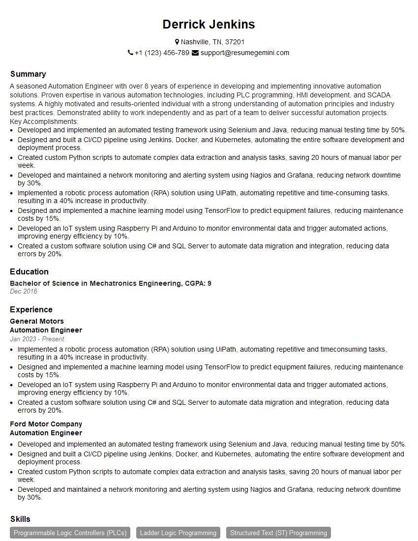
Automation Engineer Resume Sample
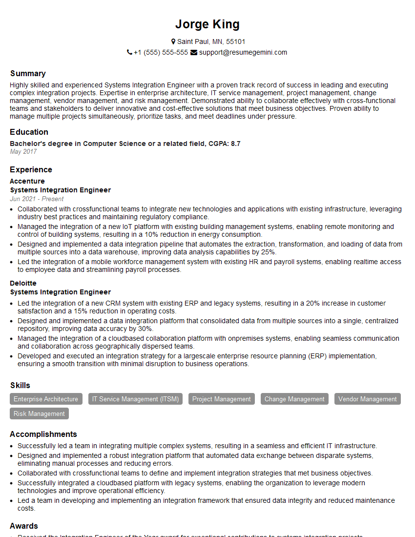
Systems Integration Engineer Resume Sample
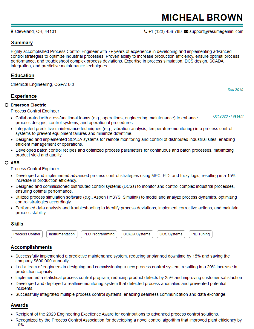
Process Control Engineer Resume Sample
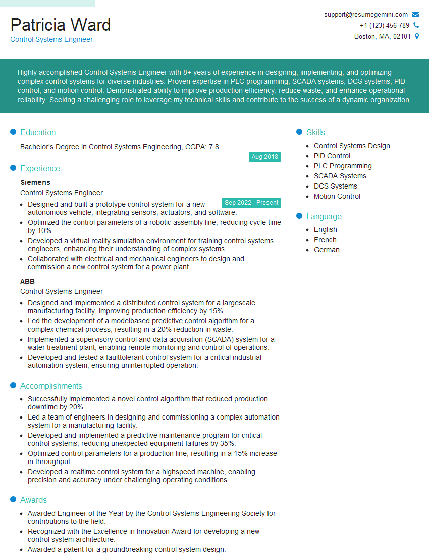
Control Systems Engineer Resume Sample
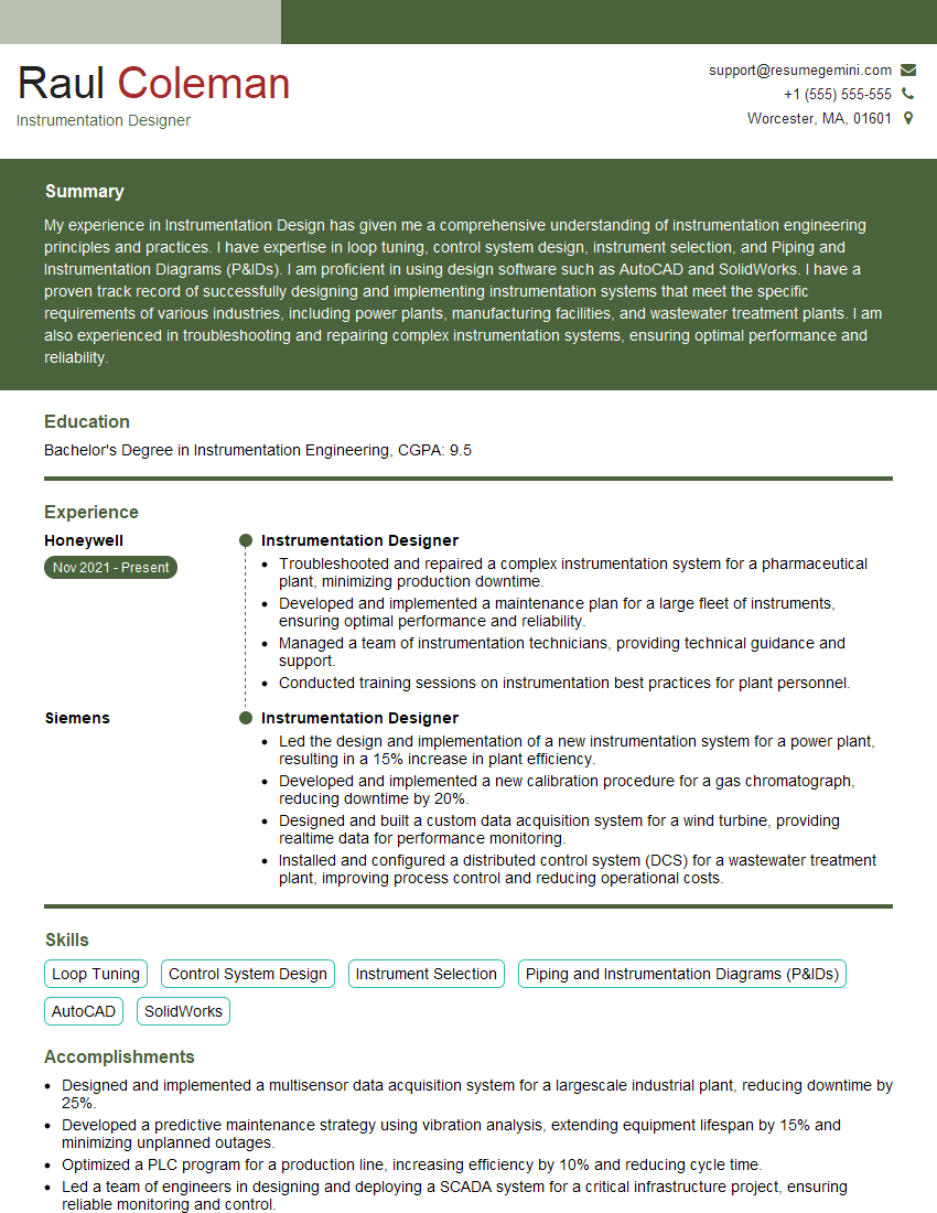
Instrumentation Designer Resume Sample
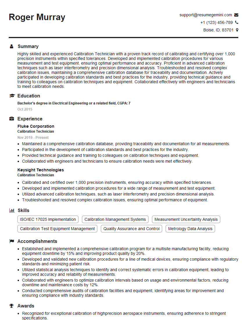
Calibration Technician Resume Sample
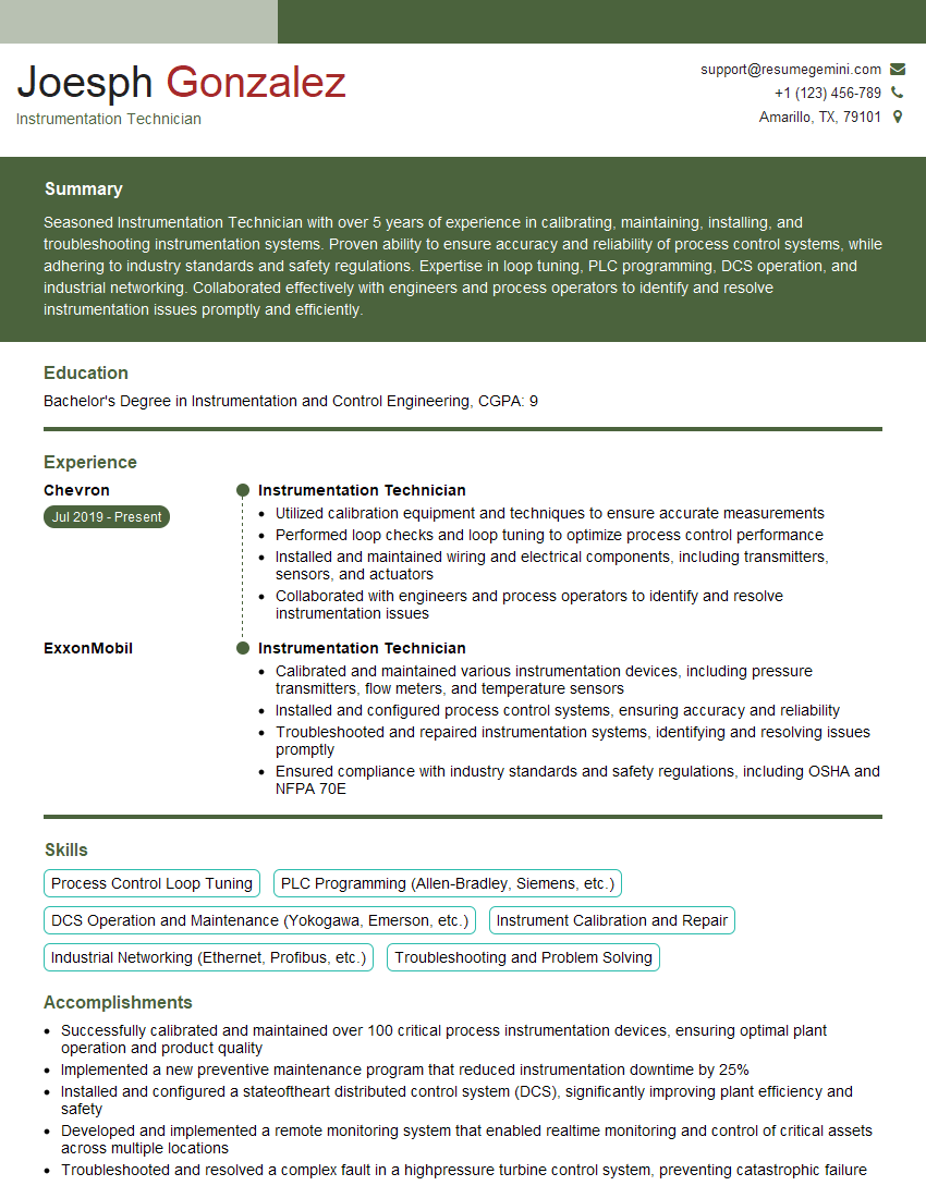
Instrumentation Technician Resume Sample
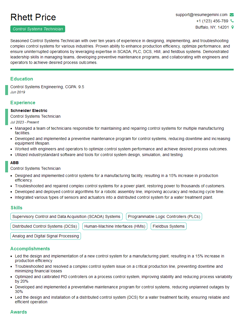
Control Systems Technician Resume Sample
Explore more articles
Users Rating of Our Blogs
Share Your Experience
We value your feedback! Please rate our content and share your thoughts (optional).
What Readers Say About Our Blog
To the interviewgemini.com Webmaster.
Very helpful and content specific questions to help prepare me for my interview!
Thank you
To the interviewgemini.com Webmaster.
This was kind of a unique content I found around the specialized skills. Very helpful questions and good detailed answers.
Very Helpful blog, thank you Interviewgemini team.